

Koy 04-K71 Product Manual
PRODUCT MANUAL
Model
04- K71
01
02
02
03
04
05
05
06
07~ 12
13~ 15
16~ 17
18
19
19
19
20
20
Dear Users,
Thanks for purchasing our products.In order to use these products safety
and effectively, please read this manual carefully before use.
We reserve the right to improve our products.
This is a currenty manual,with standard as
0
1
Content
Content
Content
Preparation
Part list
KY0718AA
KY0715CA
KY0713AA
Parameter
parts drawing
Installation drawing
KY0718AA
KY0715CA
KY0713AA
Warning
Usage Notice
Reminder
Maintainance
Trouble Shooting
Install Electricity box
Installation
Operation instruction
Aftersales service
2
0
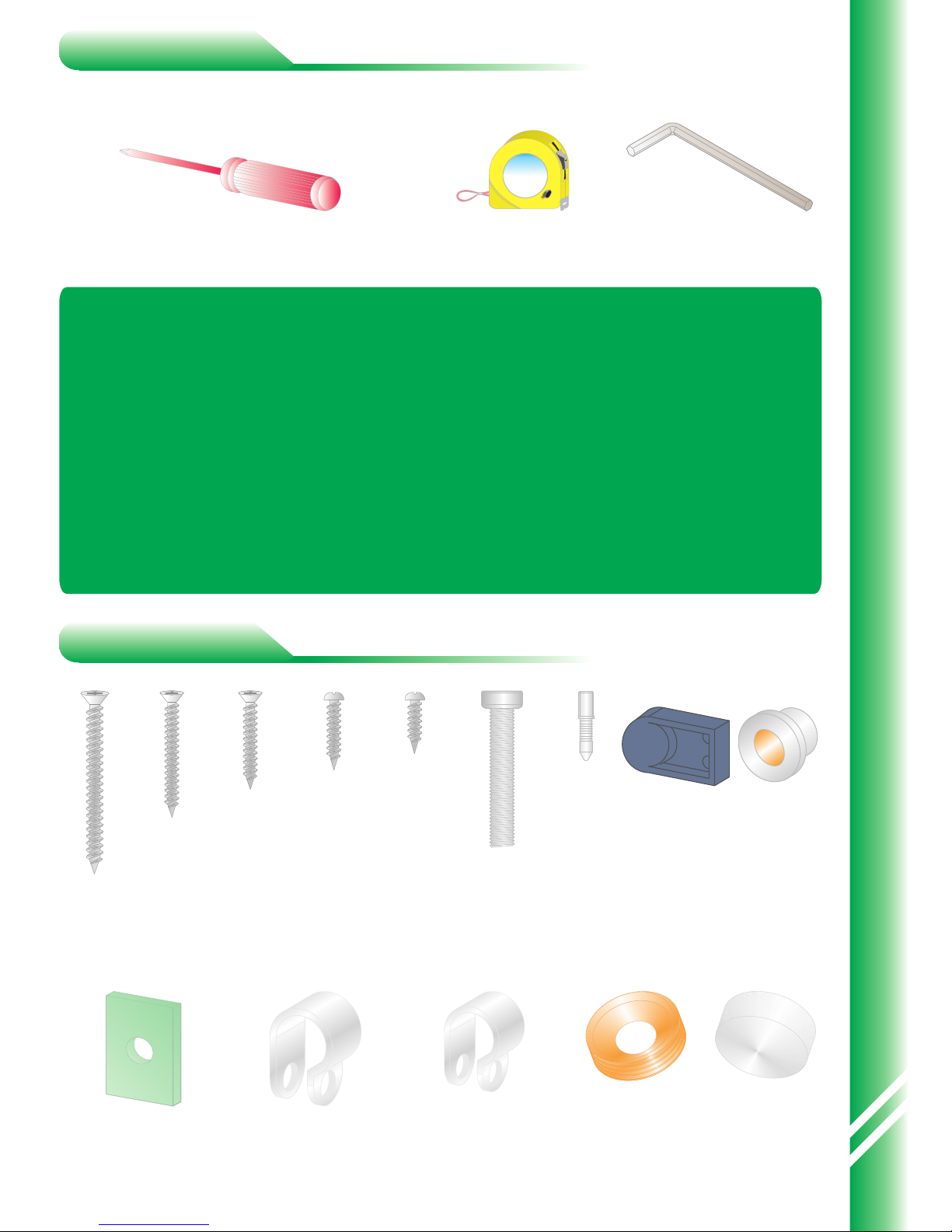
Preparation
Part list
3m
Tape Measure
8mm
Hexagon Wrench
Tool
5*60
9pcs
4*35
18pcs
4*18
14pcs
4*12
10pcs
8*45
2pcs
Heater underlay
4pcs
Ø10
3pcs
Wire fixer Ø8 Wire fixer
7pcs
Decorated
washer
2pcs
Decorated
screw cap
2pcs
Screwdriver
Suggest using power screwdriver
Preparation Part list
Flat nail
8pcs
Axes
seat
1pcs
Axes
cover
2pcs
1.Check the Qty of components according to packinglist or parts list.
2.Check the Qty of materials according to parts list.
3.Check if there is damage on the surface of product components or not.
4.A grounded outlet needed as recommend to use at least 16A with a fuse
of the leakage protection switch.
5.A professional personnel or electricians is needed when installing
electrical components.
If can not satisfy above conditions, please stop installing immediately and
contact the dealer.
4*25
4pcs
0
3
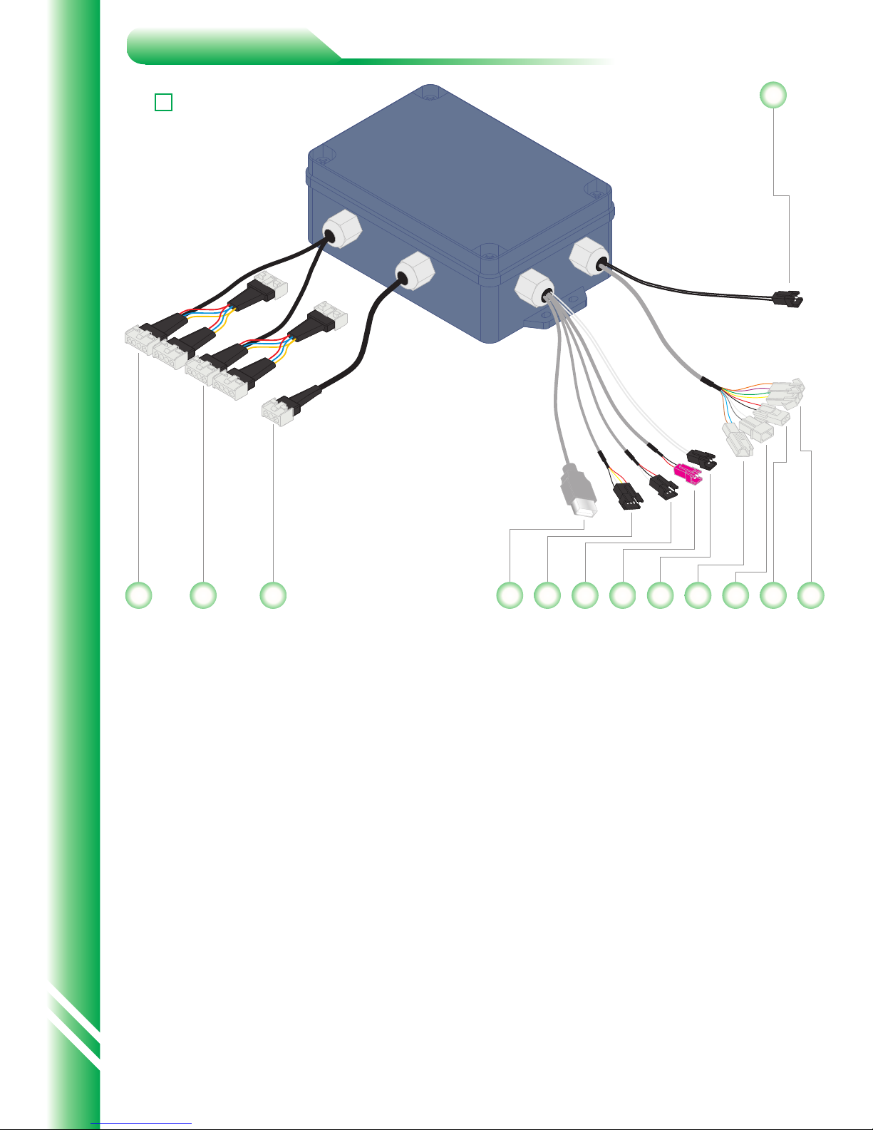
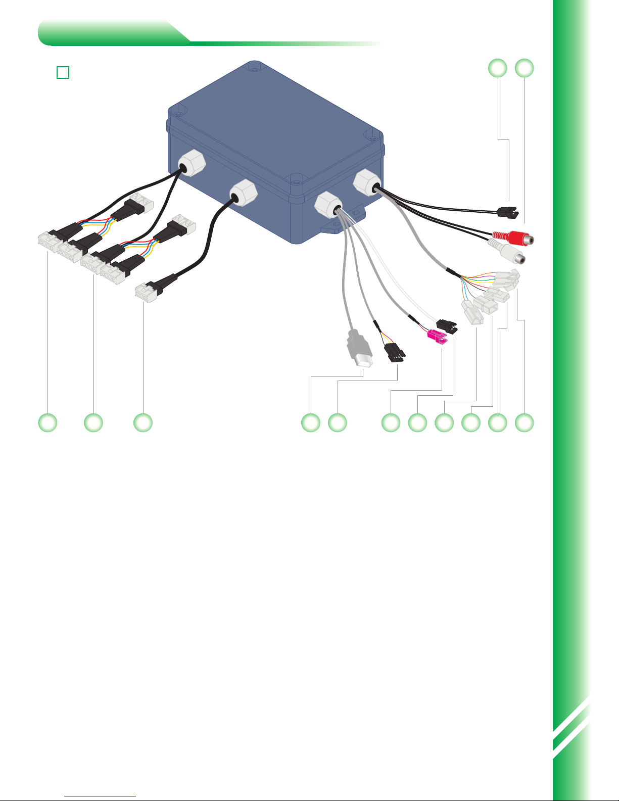
01.[Group A]Connect back heater and leg heater normally.
02.[Gprou B]Connect front heater and side heater normally.
03.[Main power supply];
04.[USB input]for U disk or memory card
05.[4P Signal wire]To get signal for control panel
06.[3PSignal wire]To get signal for external CD/MP3
07.[Temperature controller wire]To connect the back thermostat
08.[Antenna];
09.[/];
10.[Colour wire]With wiring,connecting roof lamp
11.[Fan wire]With wiring,connecting fan
12.[Speaker wire]With wiring,left and right channels,connecting speaker
13.[Temperature protector wire]To connect the temperature protector in the
cabin ,not able to work if cut the connection.
KY0718AA
01 02
03
07 08 09
10
11 12060504
13
Install Electricity box
4
0
01.[Group A]Connect back heater and leg heater normally.
02.[Gprou B]Connect front heater and side heater normally.
03.[Main power supply];
04.[USB input]for U disk or memory card
05.[4P Signal wire]To get signal for control panel
06.[Temperature controller wire]To connect the back thermostat
07.[Antenna];
08.[/];
09.[Colour wire]With wiring,connecting roof lamp
10.[Fan wire]With wiring,connecting fan
11.[Speaker wire]With wiring,left and right channels,connecting speaker
12.[Temperature protector wire]To connect the temperature protector in the
cabin ,not able to work if cut the connection.
13.[Audio wire]Connect external CD
KY0715CA
01 02
03
0504
12
13
07 08 09
10
1106
Install Electricity box

0
5
KY0713AA
01.[ ];
02.[Main power outlet];
03.[/];
04.[Colour wire]With wiring,connecting roof lamp;
05.[5PSignal wire socket]To getting signal on the control panel,not able to
work if cut the connection;
06.[Temperature protector wire]To connect the temperature protector in the
cabin ,not able to work if cut the connection.
Infrared power outlet
Technology parameters
Load parameter
Rated Voltage:AC230V
Rated Power:2220W
Rated Current:10A
Rated frequency :50~60HZ
Insulated Resistance:>20MΩ
Back/Leg heater:AC230V/300W
Side heater:AC230V/500W
Fan:DC12V/5W
Color Light:DC12V/5W
Speaker:8Ω/10W
The plug of Electric box and the load have the different shape, and with
corresponding identification stickers for the line-side, please connect them
strictly.
All electrical boxes are fixed by ST4*25 screws and intalled at the underside
of the seat in the correct place.Scattered wires are fixed by ST4*12 screws.
06
04
05
030201
Install Electricity box
6
0
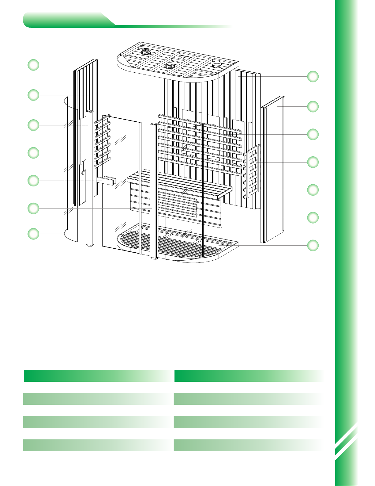
Parts drawing
No. Parts name Qty
1
Back board
left side board
Right side board
Right pillar
Top board
Model Size:
1500*1000*1980mm
2
3
4
5
6
1
1
1
1
1
1
No. Parts name Qty
8
Seat rack
Seat board
Back protective barrier
Side protective barrier
Glass window
Glass door
9
10
11
12
13
1
1
1
2
2
1
Parts drawing
01
10
07
06
02
04
09
11
03
14
08
05
12
13
Floor
7
1
Handle
14 1
Left pillar
0
7
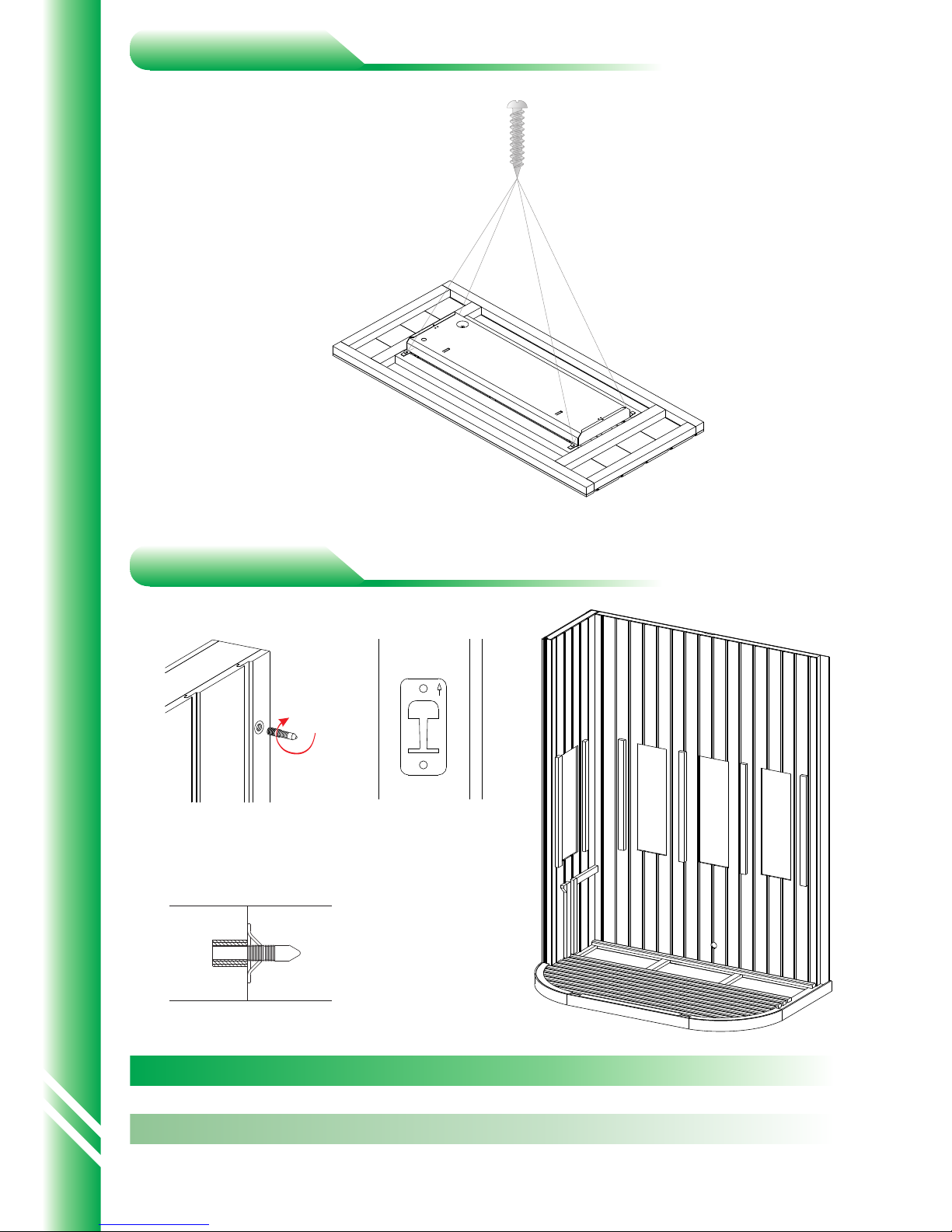
Step Material Qty
Screw
Size
ST4*18mm
Step 1
Step 2
Heater underlay
1
2
1
Flat nail
4
4
4
Installation drawing
 Loading...