

Page 1

Quantitative measurement equipment
A
600
for flare in the anterior chamber
Laser Flare Meter
W
KOWA FM-
EU
Page 2
INTRODUCTION
INTRODUCTION
Accept our congratulations on your purchase of Laser Flare Meter KOWA FM-600 (referred to as FM-600 in this
manual).
This manual provides a description of the operation procedures of FM-600 along with important precautions to
be observed during its use.
Please read this entire manual carefully to assure that the instrument can demonstrate its full capabilities and
be used effectively.
After you have finished reading it, please keep it in an easily accessible location near the instrument for future
reference.
INTENDED USE
FM-600 is an instrument to measure the protein level contained in aqueous humor of the anterior chamber.
Operational Considerations for Safety
This manual describes important precautions to be observed during its use to assure that the instrument can be
used safely without causing any damage to the human body and property of its purchaser and other persons.
The designations and their pictorial symbols have the following meanings. These should be fully comprehended before reading the text of this manual.
■ Meanings of Designations
WarningWarning
If the instrument should be operated wrongly, there may incur a risk of causing death or serious injury.
CautionCaution
If the instrument should be operated wrongly, there may result in a bodily injury (not so serious as to cause death)
damage to property
✽ 1: A bodily injury means an injury, burn, electrical shock and so forth that will not necessitate hospitalization or long-
term outpatient treatment.
✽ 2: Damage to property means an extensive damage to the house and household goods as well as the domestic animal
and pet.
■ Meanings of Symbols
Graphical indication of any danger (including warning and caution). What is warned is explicitly and
pictorially indicated by a picture or its associated message on or near a pictorial symbol.
Graphical indication of prohibited operation (prohibitive item). What is prohibited is explicitly and pictorially indicated by a picture or its associated message on or near a pictorial symbol.
Graphical indication of mandatory action (obligatory item). What must always be done is explicitly and
pictorially indicated by a picture or its associated message on or near a pictorial symbol.
✽ 2
.
✽ 1
or
■ Kowa is not responsible for;
• Any damage caused by fire, earthquake, third party’s action, any other accident or user’s intentional or
unintentional error, abuse or use under abnormal conditions;
• Any damage resulting from use of the product or its malfunction (e.g. operating loss, shutdown, change/
loss of stored data and so forth).
• Any damage resulting from disobedience of what is described in the instruction manual.
• Any damage resulting from, for instance, malfunctioning of instrument caused by a combination of connected devices.
1
Page 3
Unplug
Unplug
Obligatory
Obligatory
Obligatory
Warning
Prohibitory
Disassembly
prohibited
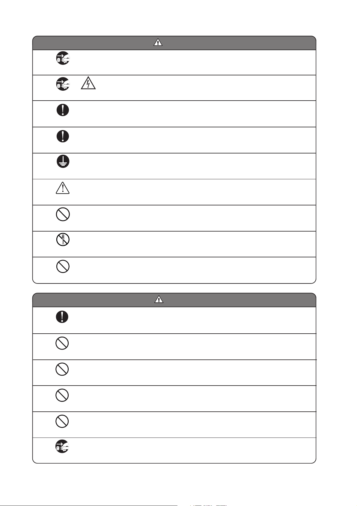
WarningWarning
If any abnormal smell or sound, or overheating or smoke should be detected, be sure to turn OFF the
main power immediately and then unplug the instrument from the power outlet. Continued use of the
instrument may cause the instrument to malfunction or cause a fire.
Contact your Kowa dealer where you have purchased the instrument or your nearest repair shop for inspection.
When replacing the fuse, be sure to turn OFF the main power and unplug the instrument from the
power outlet.
Warning
/ High-Voltage
Removing the fuse holder cover without unplugging the instrument may cause electrical shock.
Be sure to plug into the power outlet completely and securely.
Doing otherwise may cause a fire or electrical shock.
Use only a specified fuse.
Doing otherwise may cause a device failure or fire.
Be sure to ground the instrument properly and securely in order to avoid bodily injury. Be sure to
connect the plug in the three-wire grounding type socket. Doing otherwise may cause electrical shock.
Be sure that the tips of instrument are not in contact with the eye and the nose of the patient when in
operation.
(The patient may be injured.)
Do not place a cup or a glass containing liquid or the like on or near the instrument.
Spilling liquid into the instrument may cause electrical shock. If liquid should be spilled into the instrument, turn OFF the main power, and unplug the instrument from the power outlet. Contact your Kowa
dealer where you have purchased the instrument or your nearest repair shop for inspection.
Do not disassemble, modify or repair the instrument yourself. Doing so may cause a fire, electrical
shock, instrument malfunctioning or bodily injury.
Contact your Kowa dealer where you purchased the instrument for repair. The product assembled by
yourself will not be covered under warranty nor any other service.
Prohibitory
Obligatory
Prohibitory
Prohibitory
Prohibitory
Prohibitory
Do not load the socket or plug board with excess of its rated capacity.
If the main power cord should share a power outlet with other devices and the rated capacity is exceeded, there may cause a fire or electrical shock.
CautionCaution
The power supply must be provided for the sole use of this instrument.
Sharing one and the same power supply with other devices may cause FM-600 to malfunction.
Do not pull the electrical cord when unplugging.
Doing so may damage the cord and cause a fire or electrical shock. Be sure to hold the plug when
unplugging the instrument.
Do not plug or unplug the power cord with wet hand.
Doing so may cause electrical shock.
Do not install the power unit at unstable location such as on a shaky base or a tilting surface.
Doing so may cause the instrument to drop or fall over and result in a bodily injury.
Do not wipe the exterior of the instrument with solvent such as benzene, alcohol, thinner and ether.
Doing so may cause discoloration or degradation.
If the instrument is not to be in use for a long period of time, unplug the power cable.
Unplug
Leaving the power cable plugged may cause a fire.
2
Page 4
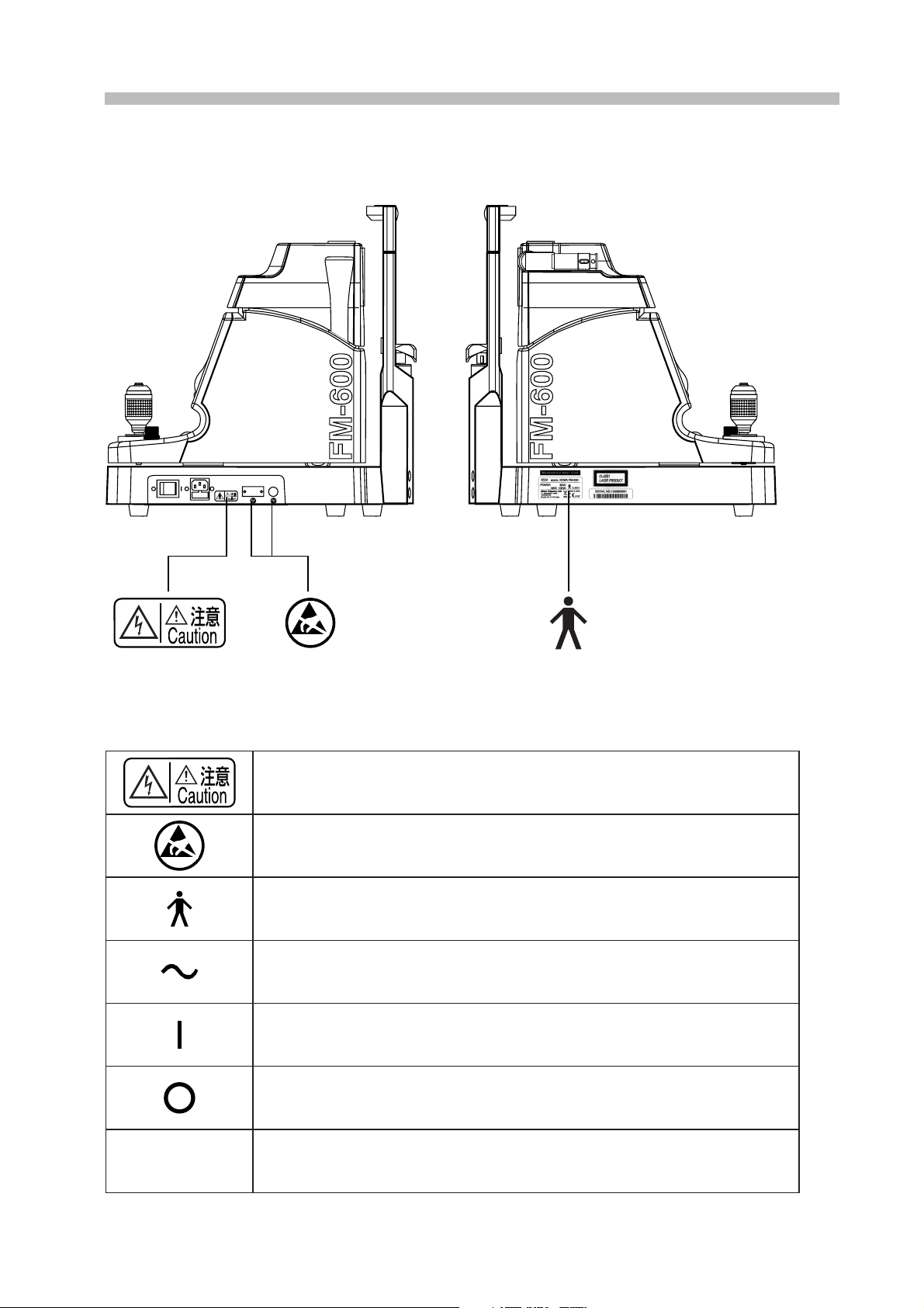
Location of Cautionary Marking
Description of Labels and Symbols
Before replacing fuse, be sure to turn OFF the main power and unplug the instrument.
Removing the fuse holder cover without unplugging the instrument may cause electrical
shock.
Do not touch directly the connector pins that are labeled with the symbols shown in the left.
❇ For details, please refer to p.36 [About electromagnetic compatibility (EMC)].
Type B applied parts (degree of protection of applied part against electric shock).
Alternative Current
ON
OFF
CLASS 1
LASER PRODUCT
Laser Class based on IEC60825-1:2001
3
Page 5
Precautions Concerning Use
• Handle the instrument with care, and do not apply strong shock to it.
Also, do not leave any objects on the instrument.
• Always cover the system when not in use in order to protect its components.
• Avoid high temperature and humidity, direct
sunlight, and dust when shipping, installing, and
storing the instrument. Strictly observe the following environmental conditions. When in use,
in storage or in transit, environmental conditions
described below must be observed strictly in order to protect the instrument from condensation.
In operation
Ambient Temperature
Relative Humidity
Precautions Concerning Use of Electrical System
• If the instrument is not to be in use for a long
period of time, turn OFF the main power and
unplug the instrument.
• Install the system in a location where there is
little risk of the plug being pulled out. If the plug
should be pulled out accidentally, be sure to turn
OFF the main power before plugging the system
back in.
• The manufacturer is not liable for malfunctions
and/or damages resulting from maintenance
and/or repairs performed by persons other than
the specified repair service.
10 - 40 °C -15 - +50 °C
30 - 60 % 10 - 95 %
Transportation, storage
• The manufacturer is not liable for malfunctions
and/or damages resulting from maintenance
and/or repairs using parts other than specified
repair parts.
• The input voltage should always be maintained
within ±10% of the rated voltage.
• Do not turn the main power on and off in succession. Allow an interval of at least 5 seconds before turning the main power on and off.
• Be sure to turn OFF the main power before plugging or unplugging the system.
Precautions Concerning Disposal of the
Instrument
• The liquid crystal display of this instrument contains mercury.
When disposing of this instrument, comply with
the regulations of countries or areas in which
the instrument is used.
Other Precautions
• Never disassemble or adjust this instrument by
yourself since it uses precision parts which requires special tool for doing so.
• It is recommended that this instrument be used
where ambient illumination is evenly distributed
at 100 lx or less (400 lx or less when using an
optional light shielding cover).
• Take the history of the patient’s medical history;
once it is confirmed that there will not be a problem with using mydriatic agent, administer mydriatic drops to him/her regardless of the
level of ambient illumination.
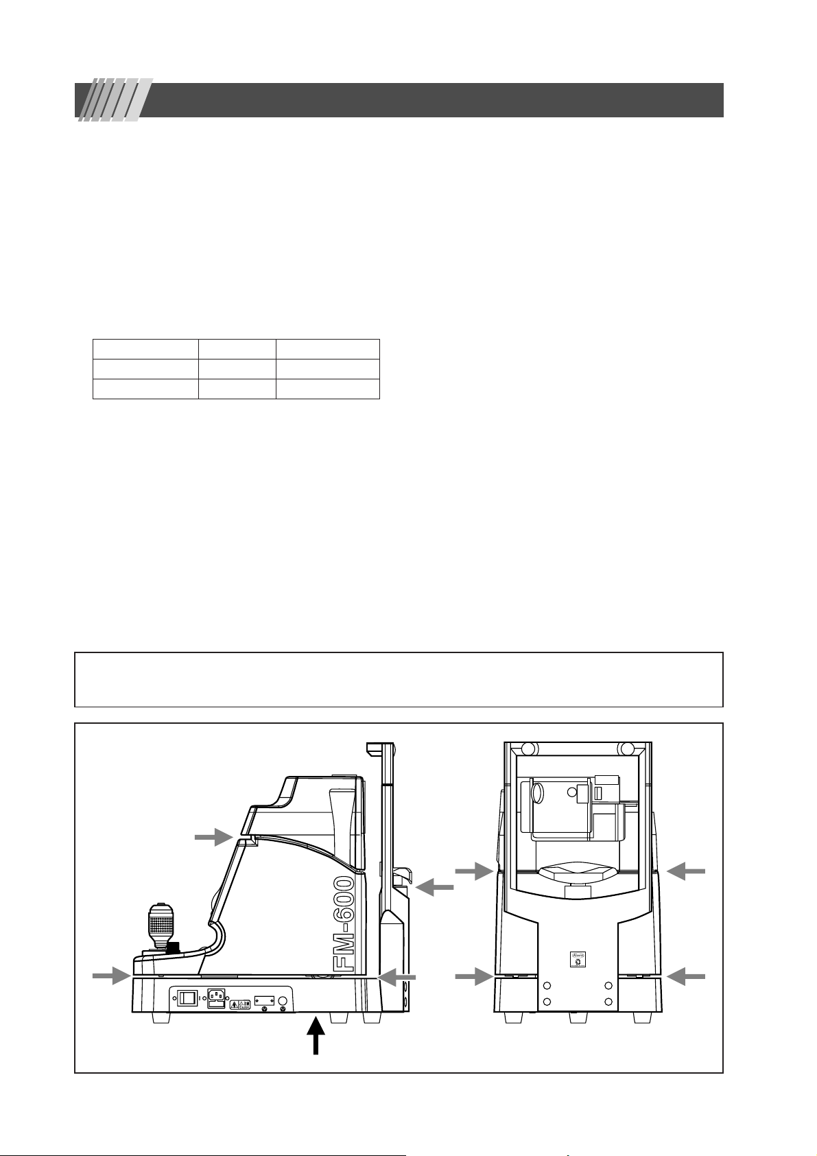
◆ Precautions during Operation
• Use special caution when operating the instrument to avoid hands being caught in the areas indicated with
arrows in the illustration below.
• There is an air vent on the bottom surface of the instrument. When installing the instrument, do not obstruct the vent.
Air vent
4
Page 6

Precautions (Safety Precautions and Hazard prevention) Concerning Use of Medical Electrical Instrument
1. Instrument should be operated only by qualified personnel.
2. The following precautions must be observed when installing the instrument:
(1) Install at a location free of moisture.
(2) Install at a location where there is no risk of detrimental effects caused by atmospheric pressure, temperature,
humidity, ventilation, sunlight, dust, salt, or air containing sulfur and so forth.
(3) Install the instrument in a stable manner, avoiding inclines, vibrations and shock (including those during transport).
(4) Do not install in locations where chemicals or pharmaceuticals are stored or where there is generation of gas.
(5) Use the proper power supply, frequency, voltage and allowable current values (or power).
(6) Check the status of battery-operated power supplies (degree of discharge, polarity, etc.).
(7) Be sure that the instrument is properly grounded.
3. The following precautions must be observed before using the instrument:
(1) The instrument must be inspected for switch contact, polarity, dial settings and meter readings to confirm its proper
operation.
(2) Be sure that the instrument is properly grounded.
(3) Be sure that all cords are connected properly and securely.
(4) Avoid combined use of instruments since this can lead to inaccurate diagnosis and hazards.
(5) Re-inspect any external circuits that come in direct contact with patients.
(6) Check all battery-operated power supplies if applicable.
4. The following precautions must be observed while using the instrument:
(1) Do not exceed the time and quantity required for diagnosis and treatment.
(2) Continuously monitor the instrument for any abnormalities as well as the condition of the patient.
(3) When an abnormality is noticed in the instrument or the patient, take appropriate measures, such as to terminating
operation of the instrument while ensuring the safety of the patient.
(4) Do not allow the patient to touch the instrument.
5. The following precautions must be observed following use of the instrument:
(1) Follow the specified procedures to return all operating switches, dials and other components to their positions prior
to use; then turn OFF the main power.
(2) When disconnecting cords, hold the plug body firmly so as not to apply excessive force to the cord itself.
(3) The following items must be observed with respect to the location where the instrument is stored.
(a) Store in a location free from moisture.
(b) Store in a location where there is no risk of detrimental effects caused by atmospheric pressure, temperature,
humidity, ventilation, sunlight, dust, salt, or air containing sulfur and so forth.
(c) Store in a stable manner while paying attention to inclines, vibrations and shock (including those during trans-
port).
(d) Do not store in locations where chemicals or pharmaceuticals are stored or where there is generation of gas.
(4) Store all accessories, cords, leads and other components in an organized manner after cleaning.
(5) Be sure to clean the instrument so that it functions properly the next time it is used.
6. If the instrument should malfunction, the operator should not attempt to correct the problem. Appropriately indicate that the instrument is not operating properly and await repairs by qualified personnel.
7. Never attempt to disassemble or modify the instrument.
8. Maintenance and inspection
(1) All instrument and components should be inspected regularly.
(2) When resuming use of instrument that has not been used for a long period of time, always confirm that the instru-
ment operates properly and safely before use.
9. Beware that strong electromagnetic waves may cause the instrument to operate incorrectly.
This instrument has been tested based on JIS T0601-1-2:2002 and IEC60601-1-2:2001. The purpose of these
standards is to maintain safety against the dangerous obstacle in typical medical facilities.
However, the instrument may affect or be affected by certain equipment such as cellular phones and pace
makers.
In case this instrument is influenced by other equipment, or it affects other equipment, or there is such fear,
relocate and/or increase the distance between FM-600 and affecting equipment.
Should there be any further questions and/or unknown points, please consult your Kowa sales representative
or dealership beforehand.
5
Page 7
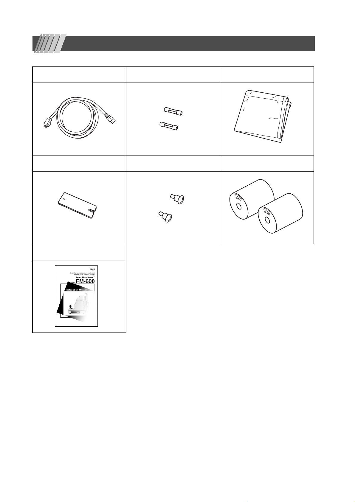
Accessories
Power cable (1) Fuse (2) Dust cover (1)
Chin-rest paper (1)
Instruction Manual (1)
Chin-rest’s pin
(2) Printer paper (2)
6
Page 8

Table of Contents
Introduction ................................................................................................................................ 1
Precautions Concerning Use .................................................................................................... 4
Precautions (Safety Precautions and Hazard Prevention)
Concerning Use of Medical Electrical Instrument .................................................................. 5
Accessories ................................................................................................................................ 6
Table of Contents ....................................................................................................................... 7
1. Principle of operation ......................................................................................................... 9
2. Names and functions of components ............................................................................. 10
2-1 Names and functions of components ......................................................................................................... 10
2-2 Screen display details ................................................................................................................................ 13
3. Setting up .......................................................................................................................... 15
3-1 Installation .................................................................................................................................................. 15
3-2 Printer paper installation ............................................................................................................................ 15
4. Basic aligning procedure ................................................................................................. 16
4-1 Coarse lengthwise / crosswise adjustment ................................................................................................ 16
4-2 Fine lengthwise / crosswise adjustment ..................................................................................................... 16
4-3 Measurement switch .................................................................................................................................. 16
4-4 Frontal view switch ..................................................................................................................................... 16
5. Calibration ......................................................................................................................... 17
5-1 Calibration .................................................................................................................................................. 17
5-2 Light shielding cover .................................................................................................................................. 18
6. Procedure for measurements .......................................................................................... 19
6-1 Procedure for measurements: Overview .................................................................................................... 19
6-2 Ocular height adjustment ........................................................................................................................... 19
6-3 Frontal view alignment ............................................................................................................................... 19
6-4 Diagonal view alignment ............................................................................................................................ 20
6-5 BG check ................................................................................................................................................... 21
6-6 Measurement ............................................................................................................................................. 21
6-7 Displaying measurement results ................................................................................................................ 22
6-8 Viewing and editing acquired data ............................................................................................................. 23
7
Page 9

Table of Contents
7. Tips for measurements .................................................................................................... 24
7-1 How to block laser beams .......................................................................................................................... 24
7-2 Warning beep during BG check ................................................................................................................. 24
7-3 Recommended procedure when BG check obtains no correct alignment ................................................. 24
7-4 Recommended procedures when BG check obtains no good result ......................................................... 24
7-5 Recommended procedures when measured waveforms are offset to left or right ..................................... 25
8. Configuration and settings .............................................................................................. 26
9. Miscellaneous ................................................................................................................... 28
9-1 ID input ....................................................................................................................................................... 28
9-2 Connecting external devices ...................................................................................................................... 28
9-3 Display messages ...................................................................................................................................... 30
9-4 Function switches ...................................................................................................................................... 31
9-5 Relocation .................................................................................................................................................. 31
10. Troubleshooting ................................................................................................................ 32
10-1 Phenomena and validation ........................................................................................................................ 32
10-2 Error messages.......................................................................................................................................... 32
11. Maintenance/Inspection ................................................................................................... 33
11-1 Daily maintenance ..................................................................................................................................... 33
11-2 Daily inspection (by the user)..................................................................................................................... 33
11-3 Fuse replacement ...................................................................................................................................... 34
11-4 Chin-rest paper installation ........................................................................................................................ 34
11-5 Sterilization of Forehead stopper and Chin-rest ........................................................................................ 34
11-6 Refilling and replacing consumables ......................................................................................................... 34
11-7 Regular inspection (by the device supplier) ............................................................................................... 34
11-8 Repairing.................................................................................................................................................... 34
12. Specifications ................................................................................................................... 35
12-1 Specifications ............................................................................................................................................. 35
12-2 Applicable safety standards and Classification .......................................................................................... 35
13. Electromagnetic Compatibility ........................................................................................ 36
14. Photochemical Hazard (ISO 15004:1997)........................................................................ 39
8
Page 10
1. Principle of operation
Weak scattered light induced by laser beam entered into the anterior chamber is detected and used for measurements.
It is known that intensity of the scattered light is proportional to the protein level contained in aqueous humor of the anterior
chamber. However, intensity of the scattered light may vary if there is a difference in the protein composition between aqueous
humor samples at the same protein concentration.
We refer to this scattered light intensity as “flare value" and indicates the value using photon count per millisecond in this device.
✽ Photon count is the number of pulses output from photomultiplier when scattered light is detected. This value may be converted
into an albumin level. Bovine albumin solution at 100mg/dl equals to 13 Photon counts per millisecond.
CautionCaution
Note that some factors including circadian rhythm, age, mydriasis, and drug may affect flare values. Measurement must be taken
carefully taking any of these factor in account. The accuracy of the reading may be affected by disorders shown below:
✽ Intensive lens clouding, corneal edema, corneal opacity, the anterior chamber with an artificial lens implanted, shallow anterior
chamber, and achromatic eye.
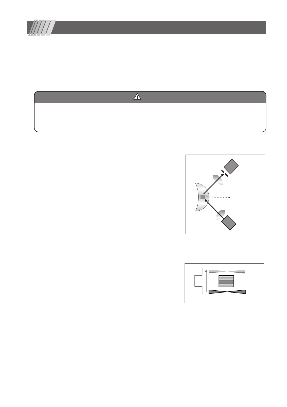
■ Details ■
Measurements
Optical system is composed of a laser beam emitter and a photoreceiver
positioned at a orthogonal to the axis of the beam. The scanning laser beam
emitted through a condensing lens is focused at the anterior chamber or
target point. Scattered light from the anterior chamber goes through a
photoreceiver lens and comes into a focus at a photoreceiver mask. The
photoreceiver mask has an important role to create a reading window within
aqueous humor of the anterior chamber. Scattered light coming through the
mask reach to a photoreceiver element (or a photomultiplier tube) where it
undergoes a photo-electro conversion process. Then, the collected data is
analyzed at the analyzer unit to determine a flare value. Results are shown
in the display.
Anterior
chamber
Photoreceiver
element
Photoreceiver
mask
Photoreceiver lens
Measurement
window
Condensing lens
Scanning laser
Details of flare reading
An area including the Measurement window is scanned with laser beam. As
a result, a waveform shown in Fig. 1-2 is obtained. Background Signal 1
(BG1) obtained when laser beam is located below the a Measurement window and Background Signal 2 (BG2) obtained when laser beam is located
above the a Measurement window are scattered light noise from intraocular
tissue, while Flare Signal (SIG) is a sum of scattered light from protein and
scattered light noise from intraocular tissue.
Therefore, intensity of the scattered light caused by the protein concentration
in aqueous humor of the anterior chamber is calculated using the formula:
SIG - (BG1 + BG2)/2.
A result obtained using this formula is called “flare value” and represented
as photon count per millisecond.
Figure 1-1
BG2
SIG
BG1
Figure 1-2
Measurement
window
Laser scanning light
9
Page 11
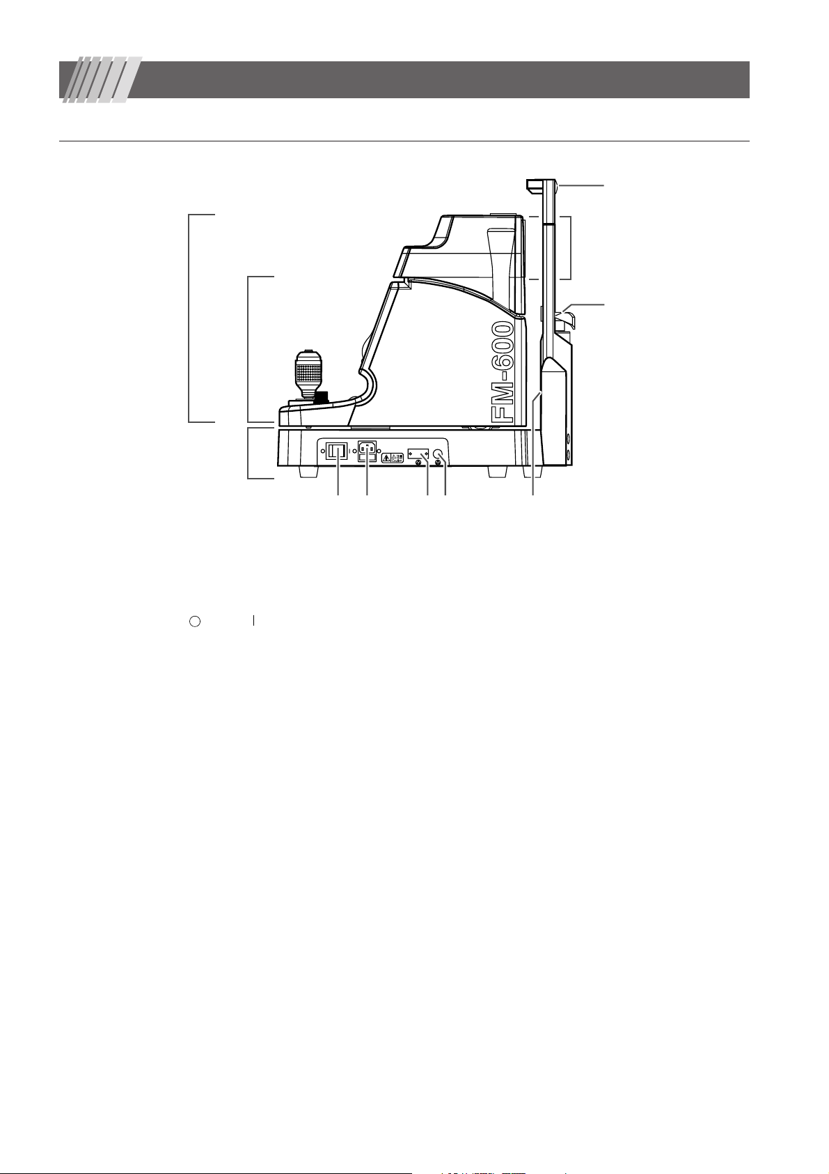
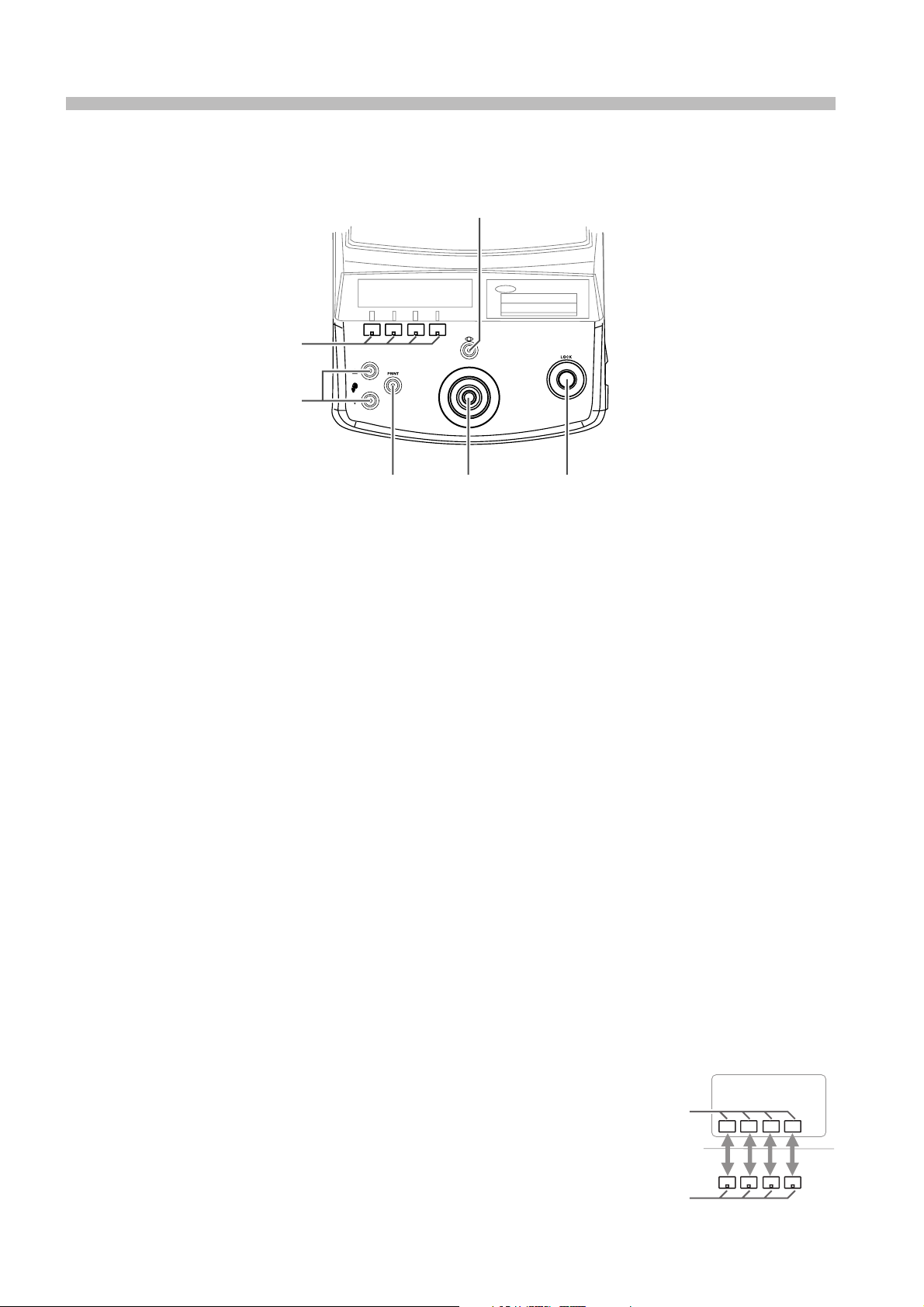
2. Names and functions of components
■
2-1 Names and functions of components
7
Measurement unit
Main unit
Operating
unit
Power supply unit
1 Power switch
: OFF : ON
2 Power supply inlet
Where a power supply cord is connected.
A fuse holder is provided.
3 External device I/O terminal (for a communication cable)
Used for connecting a PC to which measurement data outputs are transmitted.
4 External device I/O terminal (for a ten key pad)
Used for connecting a ten key pad.
5 Chin-rest illumination
Used for illuminating indirectly the patient’s eyes from a lower level than the eyes
(used in dark room).
6 Chin-rest
Used for holding patient's chin on it. A sheet of chin-rest paper may be attached.
7 Forehead rest
Used for holding patient's forehead.
The screw holes on the top are used for installing a light shade (optional
accessory) .
6
12 34 5
10
Page 12
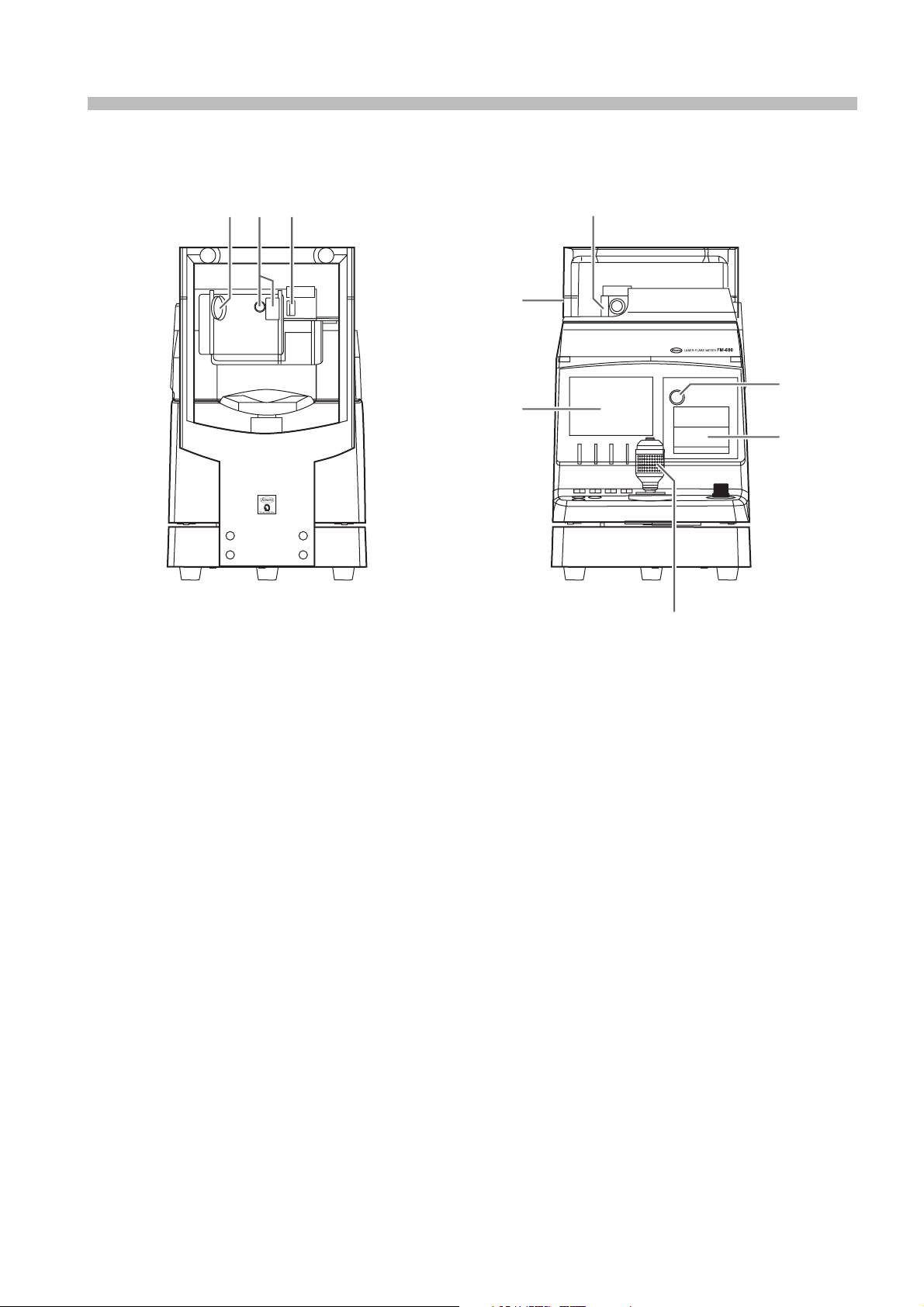
2. Names and functions of components
89 0 A
F
E
C
B
D
8 Photoreceiver lens
The lens that mainly receives scattered light.
9 Front camera and Eye fixation lamp window
Used for monitoring a patient’s eye. The patient may see the eye fixation lamp inside.
0 Light emitting lens
Used for emitting laser beam and alignment light.
A Calibrator
Used for calibrating the device.
This may be used as a laser beam attenuator when located in between a measuring
position and a calibrating position.
B Printer
Used for printing the results obtained.
C Printer lid button
The printer lid opens when the round dimple is pushed.
Used for replacing printer paper.
D Joy stick (rubber ring)
Hold and move this joy stick to move the Main unit lengthwise or crosswise for a
longer distance.
Tilt this joy stick to move the Main unit lengthwise or crosswise for a shorter
distance.
Turn the rubber ring to ascend or descend the Measurement unit.
E Display
Used for displaying Images for monitoring and obtained measurement results.
Also used for displaying each function.
F Eye level mark
This mark is a suitable position of the patient’s eye on measurement.
11
Page 13
2. Names and functions of components
K
J
L
GHI
G Self-locking screw
Tightening this screw lock the Main unit.
H Measurement switch
Pushing this switch proceeds with Frontal view alignment screen ➔ Diagonal alignment screen ( BG check ) ➔ Start measurement.
I Print switch
Pushing this switch allows contents in the display to be printed or output (only when
light is lit).
J Chin-rest ascending/descending switch
Used for ascending and descending Chin-rest.
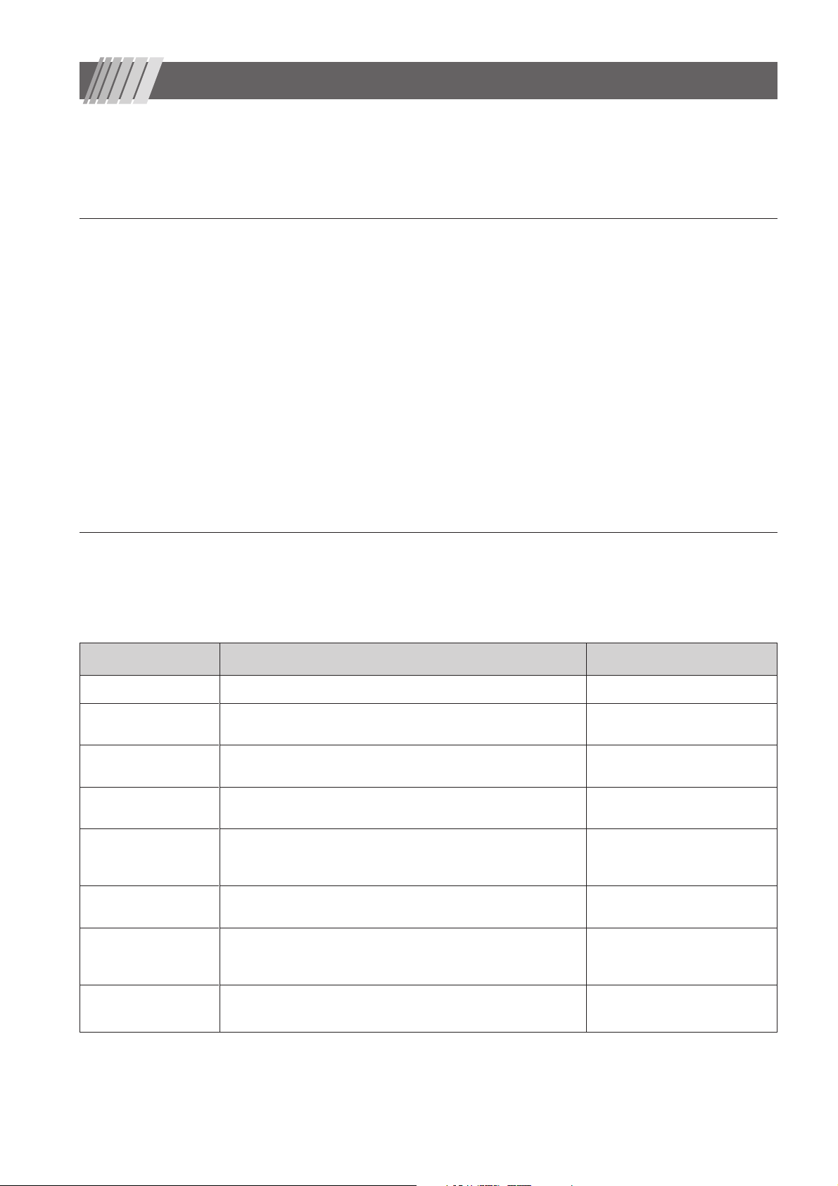
K Function switches
✽
Operates as they are assigned in accordance with each screen.
L Switches for frontal view
Pushing this switch switches the current display screen to Frontal view alignment
screen (only when the light is ).
✽
Function switches
Functions assigned to the [Function Switch Display Area]
(refer to Page 13) may vary depending on the screen you
have chosen. Each of functions shown in each screen is
selected and executed by pushing the corresponding function switch. In this manual, “select [xxx]” means pushing
the corresponding function switch.
Display
Function switch display area
Operating segment
function swiches
12
Page 14

■
2-2 Screen display details
Detail of each screen display
■ Frontal view alignment screen ■
Previous data
2. Names and functions of components
Flare value
Additional
information
Number of data saved
FLARE: 9. 5
WA: C
N: 5
Function switch display area
ID:1234567890
L
List
To change the summary data screen
Patient ID
R: Right eye
L: Left eye
Alignment mark
Corneal reflection
luminous dot
(image)
■ Diagonal alignment screen ■
Alignment mark
(for Spot light)
Measurement window
FLARE: 9. 5
WA: C
N: 5
ID:1234567890
L
ListStop
To change the summary data screenTo stop laser scanning
Pupil guide
(indicates the minimum
pupil diameter)
Alignment mark
(for laser beam)
BG level
13
Page 15

2. Names and functions of components
■ Measurements graph screen ■
BG1 SIG BG2
BG deviation =
I BG1 - BG2 I
BG1 + BG2
Background Signal 1
X 100
Obtained waveform
Background Signal 2
Flare Signal
Flare Value
= SIG - ( BG1 + BG2 ) /2
■ Summary data screen ■
Measurement No. BG average Flare value
BG1:12
BG2:10 (9%)
SIG:20
FLARE : 9
Del Scale
To save no data To change vertical scale for waveform
BG deviation
N:3
BG
S/N CELL
List
Warning
Reliability may be poor when any of the following warning
codes appears.
Warning code :Description
BG or B :Deviation between BG1 and BG2 > 15%
S / N or S :BG > Flare
CELL or C :Cell contamination
F :False data
T :Outlier candidate data
Number of data saved
Flare value average
Flare value standard deviation
To continue the ongoing
measurements using
the same eye
14
FLARE W/ANBG (%)
1 1.3 7 5.3
2 1.0 1 6.1
3 1.2 0 5.7
4 0.7 2 4.7
5 0.7 2 4.3
AV. :5.2
SD. :0.8
Cont. Edit Stat End
To edit
summary data
Statistic evaluation
for summary data
(throw out) is done
B
S
Measurements using
the same eye is completed
Page 16

3. Setting up
■
3-1 Installation
Fig. 1
Make sure that
POWER Switch is off.
■
3-2 Printer paper installation
Fig. 2 Printer lid button
Place the device on a motorized table (optional accessory).
Make sure that POWER Switch shown in Fig. 1 is at OFF position (O).
Connect the power cable to the power supply inlet and connect the other end of the
cable to a nearby wall outlet.
The printer lid opens when the round dimple “Printer lid button” is pushed.
Install a printer paper as shown in Fig. 2 and close the lid.
WarningWarning
Connect a ground cable securely to avoid injury. Connect the power supply cable to a
grounding receptacle for a triplex cable.
Fig. 3
Error 5
(Printer)
Please check printer paper. If paper is remaining.
Call a service Person.
Set
When no printer paper is installed or Printer switch is pressed while the lid is kept open,
“Please check printer paper. If paper is remaining. Call a service Person.” (see Fig. 3)
is displayed.
Make sure there is a printer paper and the lid is closed and push “Set”.
If the same message appears continuously, call a service person.
✽
This message does not appear when output mode is set to EXT. See “8.Con-
figuration and settings” for details.
✽
15
Page 17

4. Basic aligning procedure
Explanation how to operete.
■
4-1 Coarse lengthwise / crosswise adjustment
Fig. 1
■
4-2 Fine lengthwise / crosswise adjustment
Fig. 2
To move the Main unit lengthwise or crosswise for a longer distance, hold and move
the joy stick steadily (Fig. 1).
To move the Main unit lengthwise or crosswise for a shorter distance, lightly hold the
joy stick end with your finger tips and tilt the joy stick (Fig. 1).
Turn the rubber ring to ascend or descend the Measurement unit (Fig. 2).
■
4-3 Measurement switch
Fig. 3
■
4-4 Frontal view switch
Fig. 4
Use this switch to change from coarse adjustment (Frontal view alignment screen) to fine adjustment (Diagonal alignment screen) or start a Measurement (Fig. 3).
Use this switch to change from fine adjustment (Diagonal alignment screen) to coarse
adjustment (Frontal view alignment screen) or return to fine adjustment (Diagonal
alignment screen) from post-measurement (Measurements graph screen) (Fig. 4).
CautionCaution
Assure that the patient’s eye or nose does not contact with the device during this procedure.
CautionCaution
When handling the Main unit, try not to place your hand between the Main unit and the Power Supply unit or the chin-rest post and
the Forehead Rest, or into the space underneath the chin-rest.
16
Page 18

5. Calibration
CautionCaution
Stained lens may affect measurements.
It is recommended to calibrate regularly in order to obtain accurate measurements.
A message will appear during device start-up if the device had no calibration done for more than a month. Calibrate the device as
soon as possible when the message appears.
Follow the calibration procedure described below.
It is recommended to calibrate the device in a dark room.Use a light shade (optional) when calibrating in a well-lighted room.
■
5-1 Calibration
Fig. 1
Fig. 2
1 While Frontal view alignment screen is displayed, turn Calibrator to
CALIBRATION position.
If the display shows “LD Temp check Please wait”, wait until the message disappears.
If the display shows “Laser Attenuating …”, turn Calibrator until the message shown
in Fig. 3 appears in the display.
If the display shows “The acquired data is deleted. Is a calibration carried out ?”
indicating there is acquired data, select “Yes” to proceed to the calibration.
2 Slide the protective cap aside to expose the window (Fig. 2).
Caution: Do not stain the glass surface located deep inside the calibrator.
Fig. 3
Calibration
Step 1
Open the Cali. Tool the Cover
Calibration START ?
Yes No
Fig. 4
Calibration
Step 2
Input Calibration Value
Please Press "Set" After Input
2 4 0 . 0
Set
3 When “OK” is selected in the screen shown Fig. 3, “Calibration Tool's
Value” input screen appears.
4 Input the number shown in the label attached to the calibrator with
using “ ” “ ” “ ” ✽.
After this input, select “Set” to start calibration.
Calibration is automatically executed in accordance with pre-programmed steps.
✽
Although the number has been already input into the device at the factory, please verify if
the number was input correctly.
17
Page 19

5. Calibration
Fig.5
Calibration
Result
Calibration Cmplete
PMT Sens: 97.1 (%)
Corr.Value: 1.030
Set the Position Calibration tool
to the Measurement.
Fig. 6
■
5-2 Light shade
Fig. 7
5 Fig. 5 is displayed when calibration is completed.
6 Slide the protective cap back into the original position, and turn Calibrator
counterclockwise to MEASUREMENT position (Fig. 6).
Remove the white cap using a paper crip or other pointed object and
install a light shade (optional) using the screw holes on the top of the
device (Fig. 7).
Fig. 8
Fig. 9
18
When you need to directly check the level of a patient’s eye, lift the light
shade as shown in Fig. 8.
Close the light shade as shown in Fig. 9 for calibration, BG check, and
measurement.
Page 20

6. Procedure for measurements
■
6-1 Procedure for measurements: Overview
Fig. 1 shows overview of measurement procedure.
Fig. 1
Ocular height adjustment
Frontal view alignment
Diagonal alignment/
BG check
Measurement
Data summary
End
■
6-2 Ocular height adjustment
Fig. 2
Align Eye Level Mark with the patient’s eye.
Put POWER Switch into ON position “ ” .Pull back Main unit and ask the patient to sit
in front of the device.Ask the patient to rest his or her chin on Chin-rest and forehead on
Forehead rest.Move Main unit to the right proximal position where you can see the right
eye directly.Ascend or descend Chin-rest to align Eye Level Mark ( Fig. 2
the patient’s eye.Using Calibrator as an index, place Measurement unit to the same
position.Adjust crosswise position of Main unit to the patient’s eye.
[BG check] verifies the alignment status. During the
check, from the upper to lower ends including [Measurement window] are scanned. Verification results
appear in the display (see “ ■ 6-5 BG Check” ).
Data output
Data output
) with
■
6-3 Frontal view alignment
Fig. 3
Flr: 0
WA:
N: 0
ID:12345
L
Fig. 4
Flr: 0
WA:
N: 0
ID:12345
L
Perform the frontal view alignment while monitoring Frontal view
alignment screen shown in the display.
1 Frontal view of the patient’s eye is shown in the display.Move Main unit until the
luminous dot comes in the center of the display as shown in Fig. 3.
2 As shown in Fig. 4, move the luminous dot into “ ” mark and adjust the position of
Main unit or Measurement unit to reduce the size of the luminous dot as small as
possible.
After all adjustments are completed, push “Measurement switch”.
19
Page 21

6. Procedure for measurements
■
6-4 Diagonal view alignment
Fig. 5
Perform the diagonal view alignment while monitoring Diagonal view
alignment screen shown in the display.
OK
Flr: 0
WA:
N: 0
NG
Flr: 0
WA:
N: 0
ID:1234567890
ID:1234567890
Diagonal view of the patient’s eye is shown in the display.Laser beam is emitted and
L
Measurement window is shown in the display. Use Joy stick to position Measurement
window and Reflected lights as shown in Fig. 5 (OK) (see Fig.7).
When the display shows their position as shown in this picture, laser beam is hitting the
L
iris and background lights are not distributed evenly which would cause false
measurements.See Fig. 6 and re-align.
Flr: 0
WA:
N: 0
ID:1234567890
When the display shows their position as shown in this picture, there is no window
L
between two laser beams and the Measurement point is placed far away from the anterior chamber which would cause false measurements. See Fig. 6 and re-align.
Points for alignment
1. Measurement window must be between the left
and right laser beams.
2. Measurement window must be located below the
Spot light.
3. Measurement window and the right laser beam
must be within the pupil.
Fig. 6
Spot light Pupil
Points for operation
It is recommended to tilt the joy stick lightly in diagonal
directions while monitoring Diagonal view alignment
screen.
Fig. 7
20
Left laser
beam
Measurement
window
Right laser
beam
Page 22

■ 6-5 BG check
Fig. 8
Flr: 88.2
WA: B
N: 1
ID:1234567890
Stop
6. Procedure for measurements
BG check starts when Diagonal view alignment screen is displayed.
BG level appears in Measurement window.
L
(Laser emission stops automatically when a certain period of time elapses. Pressing
“Measurement switch” restarts the emission.)
Fig. 9
■
6-6 Measurement
High
Low
Level 5
Level 4
Level 3
Level 2
Level 1
Level 0
Fig. 10
BG level indicator
BG check finds out the uniformity of background lights by determining the background lights around Measurement window. Level of the uniformity appears in
Measurement window shown in the display. This is what we call “BG level indicator”. Details are shown in Figure 9.
Level 5 is the highest level that indicates background lights are distributed most
evenly, while Level 0 is the worst level that indicates the worst uniformity.
You may proceed to the measurement when the color of BG level indicator
turns to green.
You can not start the measurement when it is white.
BG level may be changed when the level does not become high. You may also
force to start the measurement regardless of the level.
Refer to “8. Configuration and setting”.
However , measurements taken at a low BG level, reliability of them would be
lowered.
Press “Measurement switch” when the color of BG level indicator turns
to green.
Measurement starts and completes in 0.5 second.
21
Page 23

6. Procedure for measurements
■
6-7 Displaying measurement results
Fig. 11
100
Results are presented in graphs and values in the display as shown in
Fig. 11. Data is automatically saved per measurement (the automatic
save function may be disabled).
50
0
0.0 0.1 0.2 0.3 0.4 0.5
BG1: 9.1 N : 7
BG2: 5.1 (28.5%)
SIG: 92.8 BG
FLARE : 85.7
Scale
Del List
Fig. 12
100
50
0
0.0 0.1 0.2 0.3 0.4 0.5
BG1: 50.1 N : 7
BG2: 23.1 (38.5%)
SIG: 50.8 BG
FLARE : 13.8
Del
Inappropriate Data Form.
Delete?
Store
Fig. 13
NAME: SEX: M / F
ID: Eye: R
100
YY / MM / DD HH:MM
● When it is not needed to save data
If you do not need data to be saved, select “Del”.
The vertical scale for graphs can be changed between 4 levels including
“0 - 100”, “0 - 200”, “0 - 500” and “0 - 1000”, when “ Scale ” is selected.
● Waveform evaluation
Flare is compared with |BG1 - BG2 | per measurement.
(SIG – BBG
(SIG – BBG
Form. Delete?
Select “ Del ” to delete or “ Store ” to save.
✽
✽
) - |BG1 - BG2 | > 0 is acceptable and no message is displayed.
✽
) - |BG1 - BG2 | 0 is unacceptable and the message “
” is displayed.
BBG is BG1 or BG2, whichever the larger.
Inappropriate Data
● Printing out the display
Pressing “Print switch” prints out the display contents as seen in the print out sheet
sample shown in Fig. 13.
● When continuously conducting multiple measurements
If you want to continue taking additional measurements, press “Measurement switch”.
BG check screen appears and you may continue the measurement.
50
0
0.0 0.1 0.2 0.3 0.4 0.5
BG1: 5.3 N: 3
BG1: 4.6 ( 6.4%)
SIG: 51.8
FLARE: 46.8
KOWA FM-600 Ver. 1.0
Print out sheet sample
● Maximum number of data savings
When measurements are repeated on the same eye, up to 10 data savings are allowed.
● Switching the display to Summary data screen
When you want to have the display to show Summary data screen, select “List”.
22
Page 24

■
6-8 Showing and editing acquired data
Fig. 14
N BG (%) FLARE W/A
1 9.8 17 20 BC
2 8.5 6 22
3 8.0 9 21
4 8.3 55
5 9.0 8 19
AV: 20.5
SD: 1.1
Summary data screen
Test Result
No. of outliers : 1
After the Test.
No. of data : 4
AV.:20.5
S.D.:1.1
Erase Outliers?
Yes No
If you have selected “List” in the display shown in the previous step,
Summary data screen appears which shows a summary listing an
average flare value and standard deviation (Fig. 14).
At the same time an outlier test is performed.
● Outlier test of acquired data
When 5 or more data has been acquired, an outlier test is performed to find any outlier
(or throw-out) candidate datum (see Additional Information below).
When the message “Erase Outliers?” appears, select “Yes” to delete or “No” to save.
Selecting “Yes” deletes the candidate data and recalculates an average flare value
(Fig. 15).
6. Procedure for measurements
Fig. 15
N BG (%) FLARE W/A
1 9.8 17 20 BC
2 8.5 6 22
3 8.0 9 21
4 9.0 8 19
AV: 20.5
SD: 1.1
Cont Edit Stat End
Fig. 16
N BG % FLARE W/A
1 9.8 17 20 BC
2 8.5 6 22
3 8.0 9 21
4 9.0 8 19
AV: 20.5
SD: 1.1
Del Set
Example:
Fig. 14 shows an example. When a significance level of 0.05 is selected and five flare
values are 20, 22, 21, 55, then 19, 55 would be a candidate.
Additional Information:
Outlier test requires at least five data. The required number of data may be changed
•
to any number between 5 and 10 (see “8. Configuration and settings”).
This outlier test uses Smirnov and Grubbs’ method and the significance level may
•
be 0.001, 0.025, 0.05, 0.1, 0.15 or 0.2 (see “8. Configuration and settings” for
details).The greater the significance level, the greater the number of throw-out candidate data would be detected.
You may also select not to perform an outlier test (see “8. Configuration and set-
•
tings”).
When there is no candidate the message “The result No. of Outliers:0 No outliers”
•
appears.
● Editing summary data
When you want to delete some data from Summary data screen, select “Edit”.
” and “ ” to select and highlight a datum.
Use “
When you select “Del”, two lines are placed over the datum (Fig. 16).
After you select all data you want to delete and select “Del”, the message “Delete the
selected data?” appears.
Selecting “Yes” deletes all the data selected and exit the editing step.
Fig. 17
NAME: SEX: M / F
ID: Eye: R
N BG (%) FLARE W/A
1 0.7 7.4 82.9
2 0.9 23.0 77.6 B
3 0.9 55.6 81.8 B
AV : 80.8
SD : 2.8
YY / MM / DD HH:MM
KOWA FM-600 Ver. 1.0
● Printing out the display
Pressing “Print switch” prints out Summary data screen contents as seen in the print
out sheet sample shown in Fig. 17.
● Continuing / ending measurement
If you want to continue taking additional measurements, select “Cont” in Summary data
screen.
Frontal view alignment screen appears (Maximum number of measurements is 10).
If you finish measurement of the current eye, select “End” in Summary data screen.
When the message “Proceed ? (Erase all data ?) ” appears, select “OK” to delete all
data and go back to Frontal view alignment screen.
Selecting “No” deletes no datum and takes you back to Frontal view alignment screen.
23
Page 25

7. Tips for measurements
■
7-1 How to block laser beams
Fig. 1
Turning Calibrator until it comes to the position shown in Fig. 1 makes a
click-sound and blocks laser beams.
Use this method to block laser beams immediately and securely. The following message appears.
If Measure / Calibrate
Set the position of Cali. Tool as follows.
Measure = Measurement
Calibrate = Calibration
■
7-2 Warning beep during BG check
Fig. 2
When intensive laser beam comes into Measuring window as shown
Laser Attenuating …
When you start measuring, turn Calibrator
counter-clockwise until it comes to MEASUREMENT.
When you start calibrating, turn Calibrator
clockwise until it comes to CALIBRATION.
in Fig. 2, Excessive light detector automatically emits a series of highpitch short repeated alarm.
When you hear this alarm, move Main unit and Measurement unit away to keep excessive laser beam from entering into Measuring window.
Caution: Excessive laser beam may cause a photoreceiver element failure.
ListStop
■
7-3 Recommended procedures when BG check obtains no correct alignment
Fig. 3
When Excessive light detector does not stop the alarm in BG check
screen, press “Frontal view switch” to go back to Frontal view alignment
screen or select “Stop” on Fig. 2.
Selecting “Stop” terminates the ongoing laser scanning and stops BG check. Realign
while monitoring the laser beam position. In order to perform BG check again, press
“Measurement switch” (Fig. 3).
■
7-4 Recommended procedures when BG check obtains no good result
Fig. 4
Reading on the eye. BG check may result in good without using the
alignment mark (Fig. 4).
Important point is to align the device so that no iris image or reflected glare comes into
Measurement window (see ■ 6-4 Diagonal view alignment).
ListStop
24
Page 26

7. Tips for measurements
■
7-5 Recommended procedures when measured waveforms are offset to left or right
Fig. 6
Wide
Fig. 7
Narrow
You may encounter waveform offset to the left as shown in Fig. 6 when
attempting a measurement at an excessively lower part of the anterior
chamber.
You can not obtain a correct flare value in this condition.
1 Select “ON” for “Laser : Position” as described in “8. Configuration and
settings” and change the laser position in BG check screen to solve this
problem.
2 Use “ ” and “ ” several times to change the laser position.
L
3 Press “Measurement switch” to perform a measurement after the position
change. This setting is effective until all measurement data for the one
examined eye are cleared✽.
ListStop
✽
Select “End” in Summary data screen.
25
Page 27

8. Configuration and settings
Fig. 1
Setting
Calibration
End
Fig. 2
Setting
Calibration
Continue Measure
End Measure
Fig. 3
Meas. Process
Illumination
Laser
Output mode
Date/Time
Sleep Time
End
Laser Flare Meter
FM-600
Ver. 1.0
Laser Flare Meter
FM-600
Ver. 1.0
Setting
Ent
Ent
1 Press and hold “Print switch” for more than 4 seconds to display the menu
screen (Fig. 1).
2 Select “Setting” using
“ ” or “ ” and select “Ent” to display Setting menu
screen.
When collected data exists, contents of the menu would be as shown in Fig. 2.
Select “ setting ” using “ ”or “ ” then select “ Ent ” to display Setting menu screen.In order to
end the setting and move to other screen, you must decide the next procedure. Use “ ” or “ ”
to select an item and select “Ent”.
Calibration (to delete collected data and perform calibration)
Continue Measure (to keep collected data and exit the menu screen)
End Measure (to open Summary data screen)
3 Use “ ” or “ ” to select an item from the screen shown in Fig. 3 and select
“Ent” to open the menu screen corresponding to the selected item.
Changing the mode of each item you may change the state of this device.
Details of each item are described below:
Ent
Meas. Process (common settings regarding measurement)
Setting menu Description Selection
“
BG Error Check
BG Error Level
Prohibiting
with a quality below BG error level.
BG error level setting, “H” for rigorous or “L” for reduced error level.
Meas. TRG Auto or manual measurement after BG error check. Auto / Manual
Alighnment Mode
Diagonal view alignment, "1" for single step or "2" for double step.
Graph View Displaying “On” or not displaying “Off” Graph View. On / Off
ID No. Input Allowing “On” or not allowing “Off” ID input. On / Off
Graph Review
Displaying
“Del” is selected to delete some data in Summary data screen.
Data Store Saving measurements automatically or manually. Manual / Auto
Data Form Evaluation Executing “On” or not executing “Off” a data shape evaluation. On / Off
Auto Statistics
Automatic, significance level, and minimum number of data
settings for outlier test.
Yes” or not prohibiting “No” a measurement
“On”
or not displaying “Off” Graph View when,
Yes / No
H / M / L
1 / 2
On / Off
Auto | 5% | 5
Shadowed items and numbers within brackets are default settings.
26
Page 28

8. Configuration and settings
Illumination settings
Setting menu Description Selection
Front View Illumination intensity settings of Frontal view alignment screen. 1 - 10
Side View Illumination intensity settings of Diagonal alignment screen. 1 - 10
Chin Light White LED illumination, “On” or “Off” . On / Off
Monitor Bright Monitor Brightness adjustment. -63 - +64 (-40)
Monitor Contrast Monitor Contrast adjustment. -63 - +64 (-40)
Laser settings
Setting menu Description Selection
Position
Default Default setting of permanent laser scanning position. -3 - +4 (0)
Off Time Setting of a period of time elapsed before aborting laser emission. 01 - 10
Allowing “On” or not allowing “Off” to change laser scanning position temporally.
Data output settings
Setting menu Description Selection
Selecting devices to which data are output.
Output to PRN : Printer only, EXT : External device only,
PRN EXT : Printer and external device.
Form Selecting “On” or not selecting “Off” contents to be printed.
Name Patient name On / Off
ID Patient ID On / Off
Sex Patient sex On / Off
Eye Examined patient eye On / Off
Data Collected data All / Result
(time when data was acquired for Measurements
Date
Date
graph screen and time when data was outputted for
Summary data screen)
.
On / Off
PRN / EXT / PRN+EXT
On / Off
Equipment Name of equipment On / Off
Date/Time settings
Setting menu Description Selection
Date Form Selecting “yy/mm/dd”, “mm/dd/yy”, or “dd/mm/yy”. YY / MM / DD
Date
Time(24h) Displaying the time (24h) when settings were made. — — —
Displaying the date when settings were made. Values may be
changed using .
Sleep time settings
Setting menu Description Selection
Sleep Time
Shadowed items and numbers within brackets are default settings.
Time setting for power saving function to become active
In order to terminate the power saving mode, press any key.
— — —
0 – 99 (10)
27
Page 29

9. Miscellaneous
■
9-1 ID input
Fig. 1
ID Input
ID No.
0000000000
SetCLR
In order to input an ID number, “ID No. Input” must be “On” (refer to “8. Configuration
and settings”). Use function keys, ten keys, or a barcode reader to input an ID number.
9-1-1 Inputting an ID number using function keys
1 Select “CLR” to clear the number shown if any
2 Use “
(the larger digit field next to the current one))
3 Use “ ” to increase the number within the current field.
4 Use “Set” to confirm the input.
” to move within the digits shown (selecting “ ” moves you to the left
9-1-2 Inputting an ID number using function keys
You need a ten key pad with a PS/2 connector. This device accepts 0 to 9 and Enter
key only. Any other key are not accepted. The primary field for a ten key pad is the right
end field (other field you have selected using a function key will be ignored and you
need to start from the right end field).
Function keys are active even when you have connected a ten key pad.
9-1-3 Inputting an ID number using a bar code reader
You need a bar code reader with a PS/2 connector. For details of configuration and
settings of a bar code reader, refer to the users’ manual supplied with your reader.
Should you have any question, contact Kowa sales representative or dealership.
■
9-2 Connecting external devices
When you use external device or software to acquire and control data, refer to the communication specifications and data
structure.
CautionCaution
The RS232C cable must be less than 2 m.
•
When you use a peripheral device and/or other device connected to the peripheral device must meet all applicable IEC stan-
•
dards.
Data processing devices must meet IEC60601-1-1 or IEC60950.
•
The system that combines such data processing devices must meet IEC60601-1-1.
The system administrator who builds such system bears all responsibility to have the system comply with requirements of
IEC60601-1-1.
Should you have any question, contact Kowa sales representative or dealership.
28
Page 30

9. Miscellaneous
1 1
1 Communication specifications
1 1
Baud rate 38400bps
Data 8bit
Parity Even
Stop 1bit
Flow control none
All data must be made of ASCII codes.
The double type is index display.
3. Data
Name or data Description Data type
YY/MM/DD HH:MM YY/MM/DD HH:MM YY/MM/DD HH:MM
L/R Examined eye (left or right) 0 = left, 1 = right
rank BG rank during measurement 0 - 5
SN Waring: S/N 0 = OK, -1 = NG
BG Waring: BG 0 = OK, -1 = NG
CELL Waring: CELL 0 = OK, -1 = NG
DF
ST Waring: ST (SG test results) 0 = OK, -1 = NG
DARK DARK Double type
BG1 BG1 Double type
BG2 BG2 Double type
Signal SIG Double type
Flare FLARE Double type
Sens Sens Double type
PMTTemp PMTTemp Double type
Waring: D/F (data form evaluation)
2 2
2 Output data structure 1: Graph data
2 2
1. Data structure
Header
Data
Graph data 512
Footer
0 = OK, -1 = NG
2. Header
Name or data Description Data type
:LSS50 HEAD Fixed
:LSS50 HEAD Fixed
ID ID No. 10digits, numeric
TempCorrect
CaliCorrect
LD_TempCheck LDTemp check ON/OFF 0/1
LD_AlarmCheck LDAlarm check ON/OFF 0/1
asterisk
0 Data type (graph) Fixed
4. Graph data
Name or data Description Data type
flr_dt Graph data Short type
5. Footer
Name or data Description Data type
:END Fixed
Temperature compensation ON/OFF
Calibrator compensation ON/OFF
Calibration execution request OFF/ON
0/1
0/1
0/1
3 3
3 Output data structure 2: Summary data
3 3
1. Data structure
Header
Data (common)
Data (individual) Repeated for as many data as collected
Footer transmission
2. Header
Name or data Description Data type
:LSS50 HEAD Fixed
:LSS50 HEAD Fixed
ID ID No. 10digits, numeric
TempCorrect
CaliCorrect
LD_TempCheck LDTemp check ON/OFF 0/1
LD_AlarmCheck LDAlarm check ON/OFF 0/1
asterisk
1 Data type (list) Fixed
3. Data (common)
Name or data Description Data type
YY/MM/DD HH:MM
L/R Examined eye (left or right) 0 = left, 1 = right
N Number of data 1 - 10
AV. Average Double type
S.D. S.D. Double type
Temperature compensation ON/OFF
Calibrator compensation ON/OFF
Calibration execution request OFF/ON
YY/MM/DD HH:MM YY/MM/DD HH:MM,
0/1
0/1
0/1
4. Data (individual)
Name or data Description Data type
Num Data number 1 - 10
BG BG average Double type
BG_diff BG amplitude (%) Double type
Flare FLARE evaluation result Double type
Sens Sens Double type
PMTTemp PMTTemp Double type
Warning_SN Waring: S/N 0 = OK, -1 = NG
Warning_BG Waring: BG 0 = OK, -1 = NG
Warning_CELL Waring: CELL 0 = OK, -1 = NG
Warning_DF
Warning_ST Waring: ST (SG test results) 0 = OK, -1 = NG
5. Send Footer
Name or data Description Data type
:END End code Fixed
Waring: D/F(data form evaluation)
0 = OK, -1 = NG
29
Page 31

9. Miscellaneous
■
9-3 Display messages
This section explains the massages that appear in the screens.
Message Description Action
LD Temp Check
Please wait
Latest Calibration Data:
(YY/MM/DD HH:mm)
Calibrate Now?
Laser Attenuating…
If Measure / Calibrate
Set the positions of Cali. Tool as follows.
Measure : Measurement
Calibrate : Calibration
ALERT
Can't hold both R&L eye data.
Keep on Measuring “L- eye”.
Or Erase all data.
Press the Joystick Button.
To Return Scanning.
Inappropriate Data Form Delete ?
Test Result
No. of Outliers, After the Test.
No. of Data, AV , S.D.
Erase Outliers ?
Temperature at the laser source
is not within the specified range.
One month has passed since last
calibration. It is recommended to
calibrate.
Laser beam may attenuate depending on the calibrator position.
While retaining the right (left) eye
data, Measurement switch is
pressed for the left (right) eye.
Time limit has passed over and
laser emission is terminated automatically.
Obtained waveform is not appropriate.
Results of the outlier test are
shown. Average and standard deviation is recalculated and displayed If any outlier datum is
cleared.
You need to wait until the temperature becomes appropriate.
Selecting “Yes” starts calibration.
Selecting “No” aborts calibration.
If you need no laser attenuation,
turn the calibrator until it comes
to MEASUREMENT or CALIBRATION.
Select “End” on the summary
table and proceed to the left
(right) eye measurement.
Pressing Measurement switch
restarts laser emission.
Selecting “Del” clears the data.
Selecting “Store” saves the data.
Selecting “Yes” clears the candidate data. Selecting “No” does
not clear them.
The result
No. of Outliers: 0.
No. Outliers.
Disply List Data.
“Unstored Data ” exists.
Press “Graph ” to store.
Clear Selected Data?
PROCEED ?
(Erase all data? )
Now transferring.
Results of the outlier test presented
no candidate data.
This message warns you about
data that need to be saved.
This message reminds you that
the data selected on Summary
screen will be cleared.
This message reminds you that
the data collected for the examined eye will be cleared before
proceeding to next measurement.
Data are now being transferred
out from the device.
You need anything to do.
By selecting “Graph” you can go
back to Measurements graph
screen where you save the data.
Selecting “List” clears the unsaved data.
Selecting “Yes” clears the data.
Selecting “No” does not clear
the data.
Selecting “Yes” clears the data,
completes a measurement, and
desplays Diagonal alignment
screen.
Wait until the data output completes.
30
Page 32

■
9-4 Function switches
Details of function switches are described in this section.
9. Miscellaneous
Function switch
Moves the cursor upwards.
Moves the cursor downwards.
Moves the cursor to the left or right.
Ent
Set
End
Yes
No
Stop
Store
Del
■
9-5 Relocation
Confirms the selected setting or item.
Confirms the setting.
Terminates the current setting screen.
Increases a parameter value.
Decreases a parameter value.
Accepts the setting.
Cancels the setting.
Poses laser scanning.
Saves the measurement(s) shown.
Deletes the measurement(s) shown.
Fig. 1
NG
Description
Follow the precautions shown below when you relocate this device:
•
•
•
•
•
•
Function switch
List
Scale
Edit
ID
CLR
Stat
Graph
Cont
Not. Cali
Move Main unit so that Main unit sits right on the top of Power Supply unit as shown
in Fig. 1.
Press down and tighten Self-locking screw clockwise as shown in Fig. 2.
Place your both hands under the Power Supply unit and lift the device. Do not lift
the device using any other part.
Make sure there is no bump or dip on the place where you relocate the device.
Make sure not to pinch your hands when placing the device in place.
Turn counterclockwise and undo Self-locking screw after placing the device.
Changes the current screen to Summary data screen.
Changes the vertical scale for waveform
graphs.
Changes the current screen to Editing
screen.
Changes the current screen to ID input
screen.
Clear the number(s) shown in ID input
fields.
Starts statistic processing.
Regenerates measurements graph from
unsaved data.
Performs additional measurement.
Performs no calibration.
Description
OK
Fig. 2
Fig. 3
Tighten
Undo
31
Page 33

10. Troubleshooting
■
10-1 Phenomena and validation
In this section, we discuss what you can do when you encounter a problem. When a problem occurs, check the items shown
below first. If none of the items is the case or if the specified remedy solve your problem, please contact your Kowa dealer
where you have purchased the instrument.
Situation Phenomena Validation (possible cause) Remedy
Alignment
Measurement
mode
Measurement
data
The display does not show the
patient’s eye (Frontal alignment
screen).
The display does not show the
patient’s eye (Diagonal alignment
screen).
The display is whitened and the
luminous dot for alignment does
not appear.
No measurement is started (Measuring window does not turn to
green).
No measurement is started (alarm
is emitted).
Data can not be saved.
BG value and BG% are too high.
There are excessive variations in
collected data.
Vertical level and the position of the
eye are not aligned with those of the
device.
The position of the eye not aligned
with the device.
No light shade is used in a welllighted room.
The ratio of BG1 to BG2 is not good.
“Yes” is selected for the setting of BG
error check.
Excessive light is detected blocking
a measurement.
Flare value is zero (0). “Store” button is not selected.
The target point is not good. The
room is well-lighted.
The target point is not good.
Pull back Base segment and perform Ocular height adjustment again (see “■ 6-2
Ocular height adjustment” on Page 19)ask
the patient to sit in front of the device.
Align the position again using Frontal alignment screen.
Settings of the display are incorrect.
Use a light shade. Adjust settings of
the display correctly. Darken the
room.
Change the target point.
Change the settings:
•
Change the laser position
•
Change BG level
• Select “No” for BG error check.
Change the target point.
Perform measurement again.
Change the target point.
Darken the room or use a light
shade.
Perform an additional measurement and
perform a test.
.
.
Nothing is printed out.
Print
Nothing is printed out.
■
10-2 Error messages
This section describes error messages that appear when a device malfunction occurs.
Any printer is not selected for Output mode.
No printer paper left.
Message Description Remedy
Error1 DARK
Error2 PMT sens
DARK count exceeded the limit.
Sensitivity of the photoreceiver element dropped below the limit.
Error3 PMT Temp. Alarm
Temperature of the photoreceiver element exceeded the limit.
Error4 LD Temp. Uncontrolled
Temperature of the laser source became uncontrollable.
Error5 Printer
Please Check Printer Paper
Error6 – 11
The printer paper roll or the lid is
wrongly positioned (see Page 15).
A system error occurred.
Select “PRN” or “PRN + EXIT” for
the output setting.
Replace with a new printer paper
roll.
Turn off the power supply and contact
Kowa sales representative.
Turn off the power supply and contact
Kowa sales representative.
Turn off the power supply and contact
Kowa sales representative.
Turn off the power supply and contact
Kowa sales representative.
If the problem continues, turn off the
power supply and contact Kowa sales
representative.
Turn off the power supply and contact
Kowa sales representative.
32
Page 34
11. Maintenance/Inspection
This instrument is a controlled medical device, of which the measurements obtained using this instrument may be affected
by daily maintenance and inspection.
In order to use this instrument safely and correctly, carefully read the items listed in this section.
■
11-1 Daily maintenance
1 Perform a calibration of this instrument a month in accordance with the procedure specified in “5. Calibration”.
2 Turn off POWER switch and place the dust cover on the instrument after use.
3 Make sure that the photoreceiver lens and the light emitting lens are not contaminated with dust, finger prints, and/or
tear fluid. When they are contaminated wipe them clean first and re-clean using a soft gauze pad or sheets of lens
cleaning paper dampened with 1:1 solution made of absolute alcohol and ether. Do not use any other agent or cloth.
4 Make sure that Eye fixation lamp window is not contaminated with dust, finger prints, and/or tear fluid. When it is
contaminated, clean using sheets of lens cleaning paper dampened with neutral detergent solution. Do not use alcohol
for cleaning.
5 When the main part of the device gets soiled, clean it with soft cloth. When the main part of the instrument gets soiled,
clean it with soft cloth. Do not use chemicals or solvents such as thinner and benzene, which cause alteration, deformation, paint-loss.
6 If the instrument is not to be in use for a long period of time, turn OFF the Power switch and unplug the instrument.
7 When resuming use of instrument that has not been used for a long period of time, calibrate the instrument in accor-
dance with the procedure specified in “5. Calibration”.
■
11-2 Daily inspection (by the user)
Perform daily inspection in accordance with “ FM-600 Daily Inspection Table ”.
When a problem is detected but can not solved with Daily maintenance procedure described above, contact Kowa or your
Kowa dealer where you have purchased the instrument.
FM-600 Daily Inspection Table
Item Inspection Criteria
Power supply cable
Printer paper
Outer shell
Rating plate, Pre-
caution plate
Light emitting lens,
photoreceiver lens
Chin-rest
Visually inspect that the power supply cable has no damage.
Determine that an appropriate amount is left.
Visually inspect that the main part does not have any crack or
deformation.
Visually inspect that contents shown on the plates are readable.
Visually inspect that the window surfaces on these lenses are
not soiled.
Press Chin-rest ascending/descending switch and visually inspect that it operates properly.
There is no damage.
There is an appropriate amount is left.
There is no crack or deformation.
Contents shown on the plates
are readable.
The lenses are not contaminated with dust, finger prints,
and/or tear fluid.
Chin-rest ascends and descends properly.
Ascending and de-
scending of Operat-
ing unit
Calibration
Turn the joy stick and visually inspect that Operating unit ascends and descends properly.
Calibrate the device in accordance with the procedure specified in “5.Calibration”.
Operating unit ascends and
descends properly.
Calibration successfully completes without any error.
33
Page 35

11 Maintenance/Inspection
■
11-3 Fuse replacement
When replacing a fuse, be sure to turn OFF the Power switch and unplug instrument from the power outlet.
Unplug
Doing otherwise may result in electrical shock.
Turn the power switch OFF, unplug the power supply plug off from the power supply
inlet and remove the fuse holder using a flat-head driver. Replace the blown fuse with a
spare fuse. Use only a specified replacement fuse.
Manufacturer: Littelfuse
Part Name (Part #): 0218001M
WarningWarning
Warning/
High-Voltage
■
11-4 Chin-rest paper installation
Chin-rest paper
Chin-rest paper
Chin-rest
■
11-5 Sterilization of Forehead rest and Chin-rest
Forehead stopper must be wiped clean with alcohol disinfectant solution every time a patient finishes an examination with
this instrument.
When you do not use a sheet of Chin-rest paper, Chin-rest must be wiped clean with alcohol disinfectant solution.
■
11-6 Refilling and replacing consumables
Item Order Number
Chin-rest paper K9L-TB45 #102
Chin-rest pins K9L-TB45 #101
Printer paper STH -148
Fuse 0218001M(T1.0A L250V)
retaining pins
Use only a specified replacement fuse. Using other fuse may cause a device failure or fire.
Place a sheet of Chin-rest paper on Chin-rest and hold the sheet with Chin-rest pins.
Use a sheet of Chin-rest paper per patient and replace it with a new sheet for a next
patient.
Order any of the required consumables with the order number
to your supplier.
■
11-7 Regular inspection (by the device supplier)
In order to use the device safely for a long period of time, it is recommended to have the following regular inspection done.
For details of inspection and its const, consult with your supplier.
Items to be inspected 1.Outer shell, installation, 2. Optical components, 3. Operation and function of components, 4. Verification
of laser power, 5. Calibration, 6. Verification of measuring functions.
■
11-8 Repairing
Contact. Your local Kowa Service representative.
34
Page 36

12. Specifications
■
12-1 Specifications
Scanning laser source
Photoreceiver element
Measurement range
Measurement accuracy
Measurement area
Measurement time
Measurement distance
Printer
Monitor
Base segment movable
range
Energy saving function
Interface
Power supply
Dimension/Weight
■
12-2 Completed safety standards and Classification
1. IEC 60601-1:1988+A1:1991+A2:1995
Semiconductor laser, Wave length: 635nm, Intensity: 35±15µW
A photomultiplier tube
1 - 500 Photon count/ms
±5%(under the calibration environment)
0.3mm (H) X 0.5mm (W)
0.5 seconds
81mm (Patient’s eye - objective lens)
58mm - wide thermal printer
5.6" TFT color LCD
Lengthwise: 37mm, Crosswise 89mm, Vertical: 25mm
Provided
ID input: PS/2 ✽ (a ten key pad and a bar code reader)
Data output RS232C
Input: AC100V - 230V, 50/60Hz, power consumption: 80VA (Normal), 100VA (Max)
274(W) X 457(D) X 458(H)mm / 18 Kg
Classification of the medical device according to on the
protection type against electrical shock
Classification of the patient attachment according to on the
protection level against electrical shock
Classification based on IEC60529: the level of protection
that electrical appliances provide against the intrusion of
water.
Classification of safe use of the device based on the level
of protection against the environment which contains air
and flammable anesthesia gases, or the environment
which contains oxygen or nitrous-oxide gas and flammable
anesthesia gases
Classification of the device based on the operation mode
2. IEC 60601-1-2:2001
3. IEC 60825-1:2001 (Laser Class : Class 1 )
4. ISO 15004:1997
Complied EC Directive
Meidcal Device Directive 93/42/EEC
WEEE Directive 2002/96/EC
Class I
Type B
IPXO
This is not a device capable of being used in such
environment.
A device capable of being operated continuously
35
Page 37

13. Electromagnetic Compatibility
This device is a medical electrical instrument. The medical electrical instrument requires special care concerning electromagnetic compatibility
(EMC). This section describes its suitability in terms of electromagnetic compatibility of this instrument. When installing or using this instrument,
please read carefully and observe what is described here. (This instrument was tested on electromagnetic compatibility (EMC) based on
IEC60601-1-2: 2001.)
1. Carefully handle portable- or mobile-type radio frequency communication unit (RF communications equipment) since it may have an
adverse effect on this instrument resulting in malfunctioning.
2. Do not directly touch the pins of the connectors specified by the right figure. Also, take preventive measures before connecting cables
to these connectors.
Examples of preventive measures are as follows;
Pay attention to the humidity of the room (do not keep the humidity too low).
•
Place the instrument where conductive floor is used.
•
Wear non-polyester clothes.
•
Discharge your body by touching a large metal or the metal part of the instrument chassis.
•
Use a wrist strap against static electricity.
•
Also, provide guidance and training, in which warnings and precautions described above must be learned by all personnel who may use this
device.
The subjects shown below may be used when providing such guidance and training.
[About Static Electricity]
All materials hold positive (+) and negative (-) electrical charges. Normally, the number of positive (+) charges is equal to the
number of negative (-) charges. This is called “neutral” state.
However, when electrons are attracted by friction, contact or abruption, the material holds more negative charges or more positive
charges (this is called “electrically charged”).
The electricity which is generated here is called “static electricity”. Static electricity is generated anytime. However, electric charges
where humidity is high leak quickly as water which is a conductor is attached to the surface of the material and the electricity
passes through the water film.
By contraries, the material where humidity is low holds a few thousands of volts as it tends to remain electrically charged.
Static electricity which is built up is discharged through the earth via other conductors. This is called “electrostatic discharge”.
When an operator with static electricity touches electronic devices or parts, they discharge static electricity, which may cause
malfunction or damage.
Therefore, be very careful with electrostatic discharge when touching electronic devices or parts. Specific measures are as follows;
Pay attention to the humidity of the room (do not keep the humidity two low).
•
Place the instrument where conductive floor is used.
•
Wear non-polyester clothes.
•
Discharge your body by touching a large metal or the metal part of the instrument chassis.
•
Use a wrist strap against static electricity.
•
These are preventive measures to avoid discharging static electricity through electronic devices or parts.
3. Do not use other than recommended options or accessories, since they may affect this device or other devices resulting in their
malfunctioning.
power cable for 100V: KP300VCTFX5SQ KSA
power cable for 200V: KP-4819Y KS-A
RS-232C cross cable with sheath (a maximum length of 3 m)
PC: A personal computer that carries CE mark, VCCI and FCC certificates.
4. This instrument is not designed such that it can be used adjacent to other instrument or placing one on top of another. Therefore, do not
apply such use. Nevertheless, if such use is inevitable, it is necessary to constantly monitor if the instrument is functioning normally
after such use has been adopted.
36
Page 38

13. Electromagnetic Compatibility
[ Compliance verification and guidance ]
Guidance and manufacturer's declaration - electromagnetic emissions
The KOWA FM-600 is intended for use in the electromagnetic environment specified below. The customer or the user of
the KOWA FM-600 should assure that it is used in such an environment.
Emissions test Compliance Electromagnetic environment guidance
RF emissions
CISPR 11
Group 1
The KOWA FM-600 uses RF energy only for its internal function. Therefore,
its RF emissions are very low and are not likely to cause any interference in
nearby electronic equipment.
RF emissions
Class A
The KOWA FM-600 is suitable for use in all establishments other than domestic and those directly connected to the public low-voltage power supply net-
CISPR 11
Harmonic emissions
Class A
work that supplies buildings used for domestic purposes.
IEC 61000-3-2
Voltage fluctuations/
Complies
flicker emissions
IEC 61000-3-3
Guidance and manufacturer's declaration - electromagnetic immunity
The KOWA FM-600 is intended for use in the electromagnetic environment specified below. The customer or the user of the KOWA FM-
600 should assure that it is used in such an environment.
Immunity test IEC 60601 test level Compliance level Electromagnetic environment - guidance
Electrostatic dis-
charge (ESD)
IEC 61000-4-2
Electrical fast tran-
sient/burst
IEC61000-4-4
Surge
IEC 61000-4-5
Voltage dips, short
interruptions and
voltage variations
on power supply
input lines
IEC61000-4-11
± 6kV contact
± 8kV air
± 2 kV for power supply
lines
± 1 kV for input/output
lines
± 1 kV differential mode
± 2 kV common mode
<5% UT
(>95% dip in UT)
for 0.5 cycle
40% UT
(60% dip in UT)
for 5 cycles
± 2, 4, 6kV contact
± 2, 4, 8kV air
± 2 kV for power supply
lines
± 1 kV for input/output
lines
± 0.5,1 kV differential
mode
± 0.5,1,2 kV common
mode
<5% UT
(>95% dip in UT)
for 0.5 cycle
40% UT
(60% dip in UT
for 5 cycles
Floors should be wood, concrete or ceramic tile. If floors
are covered with synthetic material, the relative humidity
should be at least 30%.
Mains power quality should be that of a typical commercial or hospital environment.
Mains power quality should be that of a typical commercial or hospital environment.
Mains power quality should be that of a typical commercial or hospital environment.
If the user of the KOWA FM-600 requires continued operation during power mains interruptions, it is recommended that the KOWA FM-600 be powered from an
uninterruptible power supply or a battery.
70% UT
(30% dip in UT)
for 25 cycles
<5% UT
(>95% dip in UT)
for 5 sec
Power frequency
(50/60Hz)
Magnetic field
IEC61000-4-8
NOTE UT is the A.C. mains voltage prior to application of the test level.
3 A/m
70% UT
(30% dip in UT)
for 25 cycles
<5% UT
(>95% dip in UT)
for 5 sec
3 A/m
Power frequency magnetic fields should be at levels
characteristic of a typical location in a typical commercial or hospital environment.
37
Page 39

13.Electromagnetic Compatibility
Guidance and manufacturer's declaration - electromagnetic immunity
The KOWA FM-600 is intended for use in the electromagnetic environment specified below. The customer or the user of the KOWA FM600 should assure that it is used in such an environment.
Immunity test IEC 60601 test level Compliance level Electromagnetic environment - guidance
Portable and mobile RF communications equipment
should be used no closer to any part of the KOWA FM600, including cables, than the recommended separation distance calculated from the equation applicable to
the frequency of the transmitter.
Recommended separation distance
Conducted RF
IEC 61000-4-6
Radiated RF
IEC 61000-4-3
NOTE 1 At 80MHz and 800MHz, the higher frequency range applies.
NOTE 2 These guidelines may not apply in all situations. Electromagnetic propagation is affected by absorption and reflection from
structures, objects and people.
a Field strengths from fixed transmitters, such as base stations for radio (cellular/cordless) telephones and land mobile radios,
amateur radio, AM and FM radio broadcast and TV broadcast cannot be predicted theoretically with accuracy. To assess the
electromagnetic environment due to fixed RF transmitters, an electromagnetic site survey should be considered. If the measured
field strength in the location in which the KOWA FM-600 is used exceeds the applicable RF compliance level above, the KOWA
FM-600 should be observed to verify normal operation. If abnormal performance is observed, additional measures may be necessary, such as reorienting or relocating the KOWA FM-600.
b Over the frequency range 150kHz to 80MHz, field strengths should be less than 3 V/m.
3 Vrms
150 kHz to 80 MHz
3 V/m
80 MHz to 2.5 GHz
3 V
3 V/m
d=1.2 P
d=1.2 P 80 MHz to 800 MHz
d=2.3 P 800 MHz to 2.5 GHz
where P is the maximum output power rating of the
transmitter in watts (W) according to the transmitter
manufacturer and d is the recommended separation distance in meters (m).
Field strengths from fixed RF transmitters, as determined by
an electromagnetic site survey a, should be less than the
compliance level in each frequency range b.
Interference may occur in the vicinity of equipment
marked with the following symbol:
Recommended separation distances between portable and mobile RF communications equipment
and the KOWA FM-600
The KOWA FM-600 is intended for use in an electromagnetic environment in which radiated RF disturbances are controlled. The
customer or the user of the KOWA FM-600 can help prevent electromagnetic interference by maintaining a minimum distance between
portable and mobile RF communications equipment (transmitters) and the KOWA FM-600 as recommended below, according to the
maximum output power of the communications equipment.
Rated maximum output power
of transmitter
W
0.01
0.1
1
10
100
For transmitters rated at a maximum output power not listed above, the recommended separation distance d in meters (m) can be
estimated using the equation applicable to the frequency of the transmitter, where P is the maximum output power rating of the transmitter
in watts (W) according to the transmitter manufacturer.
NOTE 1 80MHz and 800MHz, the separation distance for the higher frequency range applies.
NOTE 2 These guidelines may not apply in all situations. Electromagnetic propagation is affected by absorption and reflection from
structures, objects and people.
150 kHz to 80 MHz
D=1.2 P
0.12
0.37
Separation distance according to frequency of transmitter
m
80 MHz to 800 MHz
d=1.2 P
0.12
0.37
1.2
3.7
12
1.2
3.7
12
800 MHz to 2.5 GHz
d=2.3 P
0.23
0.74
2.3
7.4
23
38
Page 40

14. Photochemical Hazard (ISO 15004:1997)
• The relative spectral output of the instrument
(µW/(cm2 • nm))
5
4
3
2
1
Power( W) for illumination light
Energy( J) for image capturing light
0
300 400 500 600 700
Wavelength (nm)
• The spectrally-weighted photochemical source radiance, both aphakic LB and aphakic LA
2
LB = 0.0352 mW/(cm
LA = 0.0352 mW/(cm
•
sr) 305nm to 700nm
2
•
sr) 305nm to 700nm
(informative)
Spectrally weighted photochemical radiances LB and LA give a measure of the potential that exists of a beam of
light to cause photochemical hazard to the retina. LB gives the measure for eyes in which the crystalline lens is in
place. LA gives this measure either for eyes in which the crystalline lens has been removed (aphakes) and has not
been replaced by a UV-blocking lens or for the eyes of very young children.
The value stated for this ophthalmic instrument gives a measure of hazard potential when the instrument is oper-
2
ated at maximum intensity and maximum aperture. Values of LB or LA over 80mW/(cm
•
sr) are considered high for
beams which wholly fill a dilated pupil.
The retinal exposure dose for a photochemical hazard is a product of the radiance and the exposure time. For
2
instance, at a radiance level of 80mW/(cm
•
sr), 3 min irradiation of the dilated (8mm diameter) pupil would cause
the retinal exposure dose level to attain the recommended exposure limit. If the value of radiance were reduced to
2
40mW/(cm
•
sr), twice that time (i.e.6min) would be needed to reach the recommended limit. The recommended
exposure dose is based on calculations arising from the American Conference of Governmental Industrial Hygienists (ACGIH) - Threshold Limit Values for Chemical Substances and Physical Agents (1995-1996 edition).
While no acute optical radiation hazards have been identified for ophthalmic instruments, it is recommended that
the intensity of light directed into the subject's eye be limited to the minimum level which is necessary for diagnosis.
Infants, aphakes and persons with diseased eyes will be at greater risk. The risk may also be increased if the
person being examined has had any exposure with the same instrument or any other ophthalmic instrument using
a visible light source during the previous 24 h. This will apply particularly if the eye has been exposed to retinal
photography.
39
Page 41

For EU market.
40
Page 42

41
Page 43

(World Sales Headquarters)
4-14, Nihonbashi-honcho 3-chome, Chuo-ku, Tokyo 103-8433 Japan
Phone: 81(3) 3279-7331
Facsimile: 81(3) 5255-7516
Hamamatsu Factory
3-1, Shinmiyakoda 1-chome, Hamamatsu city, Shizuoka Pref., 431-2103 Japan
Printed on recycled paper.
Immermannstrasse 43B
40210 Duesseldorf F.R. Germany
Phone: 49(211) 1793540
Facsimile: 49(211) 161952
© 2006 Kowa Company, Ltd. All rights reserved.
LSS50 V1.0 E 061208 MS
Printed in Japan
0197
 Loading...