

Page 1
- 1 -
KOVARSON s.r.o.
Lhota u Vsetína 4
755 01, Vsetín
tel. ČR: +420 571 420 926
tel. SR: +421 949 176 717
email: info@kovarson.cz
Installation and operation manual automatic
boiler
TIGER
Page 2

- 2 -
Dear customer,
Thank you for purchasing an automatic solid fuel TIGER boiler and the trust you have
put in KOVARSON s.r.o.
Please read this manual before putting your new boiler into operation to avoid
unnecessary complications resulting from handling issues. Section 7 – Operating the
Boiler by the User, Section 8 – Important Instructions, Section 9 – Maintenance and
the Operation Manual for the LIDER Control Unit are particularly important.
To ensure a long and trouble-free boiler life, please follow the manufacturer’s
instructions as well as those of the authorized installation company that sets up your
boiler.
Page 3

- 3 -
Content:
1. Boiler uses and benefits ..................................................................................... - 4 -
2. Boiler technical specifications ............................................................................. - 4 -
3. Recommended fuel............................................................................................. - 6 -
4. Description .......................................................................................................... - 7 -
4.1 Boiler construction ......................................................................................... - 7 -
4.2
Control, regulation and safety elements ...................................................... - 10 -
5. Location and installation ................................................................................... - 11 -
5.1 Regulations and Requirements ................................................................... - 11 -
6. Boiler installation .............................................................................................. - 15 -
6.2 Installation procedure .................................................................................. - 16 -
7.1 Electrical Wiring .......................................................................................... - 20 -
7.2 Pre-fire-up check list ................................................................................... - 21 -
7.3 Control unit parameters setting ................................................................... - 22 -
7.4 Putting the boiler into operation - Firing up ................................................. - 23 -
7.5 superior regulation – room thermostat ............................................................ - 25 -
8. Important instructions ....................................................................................... - 26 -
9. Maintenance ..................................................................................................... - 27 -
10. Disposal of the product after a period of his life .............................................. - 28 -
11. Guarantee and liability for defects .................................................................. - 28 -
12. Trouble shooting ............................................................................................. - 29 -
EC DECLARATION OF CONFORMITY ............................................................... - 30 -
Page 4

- 4 -
1. Boiler uses and benefits
The TIGER boiler is designed to heat households, commercial buildings and other
medium-sized structures economically and ecologically using an automatically
controlled feeder for solid fuels and with minimal servicing. It can also be used as a
boiler for domestic hot water (DHW).
Boiler benefits:
− high efficiency
− cast iron body manufactured by a well-known Czech producer
− high exchanger durability
− universal burner - burns brown coal or wood pellets
− simple boiler controls
− unattended operation, boiler maintenance takes 10 minutes every 3 days
− electronically controlled fan speed managed by the control unit
− low power consumption
− in warm seasons, it can be used to heat DHW only
− controlled by a room thermostat
− option to order the boiler with the large hopper on the right or left
2. Boiler technical specifications
Tab.1 Dimensions and technical parameters of the boiler
Boiler model
TIGER
20
TIGER
25
TIGER
30
TIGER
35
TIGER
40
TIGER
48
TIGER
55
Number of sections pcs
4 5 6 7 8 9 10
Weight kg
384 438 547 594 634 713 778
Water volume l
33.3 35 44.7 50.4 56.1 61.8 67.5
Flue diameter mm
160 160 160 160 180 180 180
Combustion chamber
volume
dm3
37.5 51 64.5 78 91.5 105 118.5
Combustion chamber
depth
mm
295 405 515 625 735 845 955
Hopper capacity dm3 290 290 290 290 290 290 290
Boiler dimensions mm see Figure 1
Size of hopper loading
window
mm 370x335 370x335 370x335 370x335 370x335 370x335 370x335
EN 303-5 boiler class - 3 3 3 3 3 3 3
Maximum operating
excess water pressure
tolerance
bar 3
Tested operating excess
water pressure tolerance
bar 6
Recommended operating
temperature of heating
water
°C 60 - 85
Minimum temperature of
returning water
°C 60
Hydraulic pressure loss in
the boiler at ΔT= 20/10K
mbar
0.55÷1.82 0.76÷2.635 0.97÷3.45 1.15÷4.23 1.29÷5.08 1.5÷5.9 1.74÷6.71
Noise level dB 67
Flue draw when the
emissions fan is running
and system is at nominal
output
Pa 14 14 14 14 17 19 22
Page 5

- 5 -
Boiler connections - water
heating
Js G 2"
- returning
water
Js G 2"
Supply voltage V 230
Electric load
(fan + motor)
W 170 170 170 170 170 210 210
International protection
rating
- IP20 IP20 IP20 IP20 IP20 IP20 IP20
Tab.2 Thermal technical parameters of the boiler (brown coal combustion)
Boiler model
TIGER
20
TIGER
25
TIGER
30
TIGER
35
TIGER
40
TIGER
48
TIGER
55
Number of sections pcs
4 5 6 7 8 9 10
Nominal output kW 20 25 30 35 40 50 55
Minimum output kW 6 7.5 9 10.5 12 15 16.5
Consumption of fuel at
nominal output
kg.h
-1
4.2 4.9 5.5 6.8 8.1 9.4 10.7
Consumption of fuel at
minimum output
kg.h
-1
1,2 1,4 1,7 2,0 2,3 2,7 3,0
Burning time at nominal
output
h > 6 > 6 > 6 > 6 > 6 > 6 > 6
Efficiency % 79.9 79.5 79.2 78.8 78.5 78.3 78.1
temperature of emissions
at nominal output
°C 182 172 166 157 163 169 175
temperature of emissions
at reduced output
°C 97 101 105 109 106 103 100
Volume of emissions
output at nominal level
kg.s
-1
0.018 0.020 0.022 0.024 0.031 0.038 0.045
Volume of emissions
output at reduced level
kg.s
-1
0.008 0.010 0.012 0.013 0.017 0.020 0.024
Thermal technical parameters of the boiler (wood pellets combustion)
Boiler model
TIGER
20
TIGER
25
TIGER
30
TIGER
35
TIGER
40
TIGER
48
TIGER
55
Number of sections pcs
4 5 6 7 8 9 10
Nominal output kW 20 25 30 35 40 50 55
Minimum output kW 6 7.5 9 10.5 12 15 16.5
Consumption of fuel at
nominal output
kg.h
-1
5.0 6.1 7.3 8.4 10.2 12.1 14.0
Consumption of fuel at
minimum output
kg.h
-1
1.5 1.8 2.2 2.6 3.0 3.4 3.8
Burning time at nominal
output
h > 6 > 6 > 6 > 6 > 6 > 6 > 6
Efficiency % 83.4 83.0 82.6 82.2 82.2 82.1 82.1
temperature of emissions
at nominal output
°C 157 155 152 150 150 150 150
temperature of emissions
at reduced output
°C 96 97 99 102 98 94 91
Volume of emissions
output at nominal level
kg.s
-1
0.014 0.017 0.021 0.024 0.030 0.036 0.041
Volume of emissions
output at reduced level
kg.s
-1
0.008 0.010 0.012 0.013 0.014 0.015 0.016
These values vary depending on the quality and type of fuel. Therefore, it is necessary
to make corrections when adjusting the feeding cycle and fan speed. If, for example,
Page 6

- 6 -
there is unburned fuel in the ash pan, the fan speed or feeding cycle needs to be
adjusted. Or, conversely, if the burning fuel in moves toward the feeder, the fan speed
should be reduced or more fuel added!
3. Recommended fuel
Warranty fuel parameters– fuel with which the tests were carried out in the National
Testing Facility:
• Moisture content
• The content of volatile matter
• Ash fusion temperature
• Low sintering capacity
• Low expansion capacity
Tab.3 Fuel tested
Fuel Fuel type Operation
Granularity
[mm]
Heating value
[MJ.kg-1]
Brown coal
nut 2 Automatic 10.25 16,5 - 19,5
B
iomass
Wood pellets Automatic Ø6-8 15 - 19
Tab.4 Fuel tested - brown coal (automatic operation)
fuel
Diameter
[mm]
Heating
value
[MJ.kg-1]
the ash
content
[%]
moisture
content
[%]
sulfur
content
[%]
specific
sulfur
content
[g/MJ]
Tar
content
in dry
matter
[%]
Tar content
in
combustible
elements
[%]
Sorted brown
coal from the
Bílina Mine
(Úpravna uhlí
Ledvice) - nut 2
10.25 17.6 9.8
maximum
20
0.77 0.44 15.1 15.71
Wood pellets must satisfy at least one of the following specifications or standards:
• Specification number 14-2000 MŽP ČR
• DIN 517 31
• ÖNORM M 7135
Prescribed diameter of pellets 6 – 8 mm
Moisture content in a fuel maximum 12%
Ash content maximum 1.5%
CAUTION! Poor quality pellets may negatively affect output and boiler emission
parameters.
Page 7

- 7 -
4. Description
4.1 Boiler construction
The boiler construction meets ČSN EN 303-5 : 2000 requirements:
- boiler for CH - Part 5: boiler for DHW using solid fuel with manual or automatic
feeding, at a nominal heat output of up to 300 kW Terminology, requirements, testing and marking.
The core of the boiler is the cast-iron body. The body is composed of front, rear and
middle sections. The main function of the boiler body is to transfer thermal energy from
the exhaust gas to heat water. The upper cleaning door and the middle door are
located on the front section. The smoke extension that funnels emissions to the flue is
located on the back section.
The cast iron body is set on the base. The base is made from a 5mm-sheet of steel.
The ash pan door is on the front of the base.
The burner is placed into the side wall of the base. The feeder shaft extends into the
burner, where it is fastened on the far side. The screw feeder extends to the
combustion chamber and pushes against a counter screw, which forces the fuel
upwards. The upper part of the burner is made from two cast-iron rings.
Two ceramic plates are positioned inside the boiler body in front of the cleaning door
to improve combustion.
The burner’s ash pan is placed at the bottom of the base.
The burner is fed air by a fan placed on the flange of the burner under the fuel hopper.
The fan can be regulated electronically.
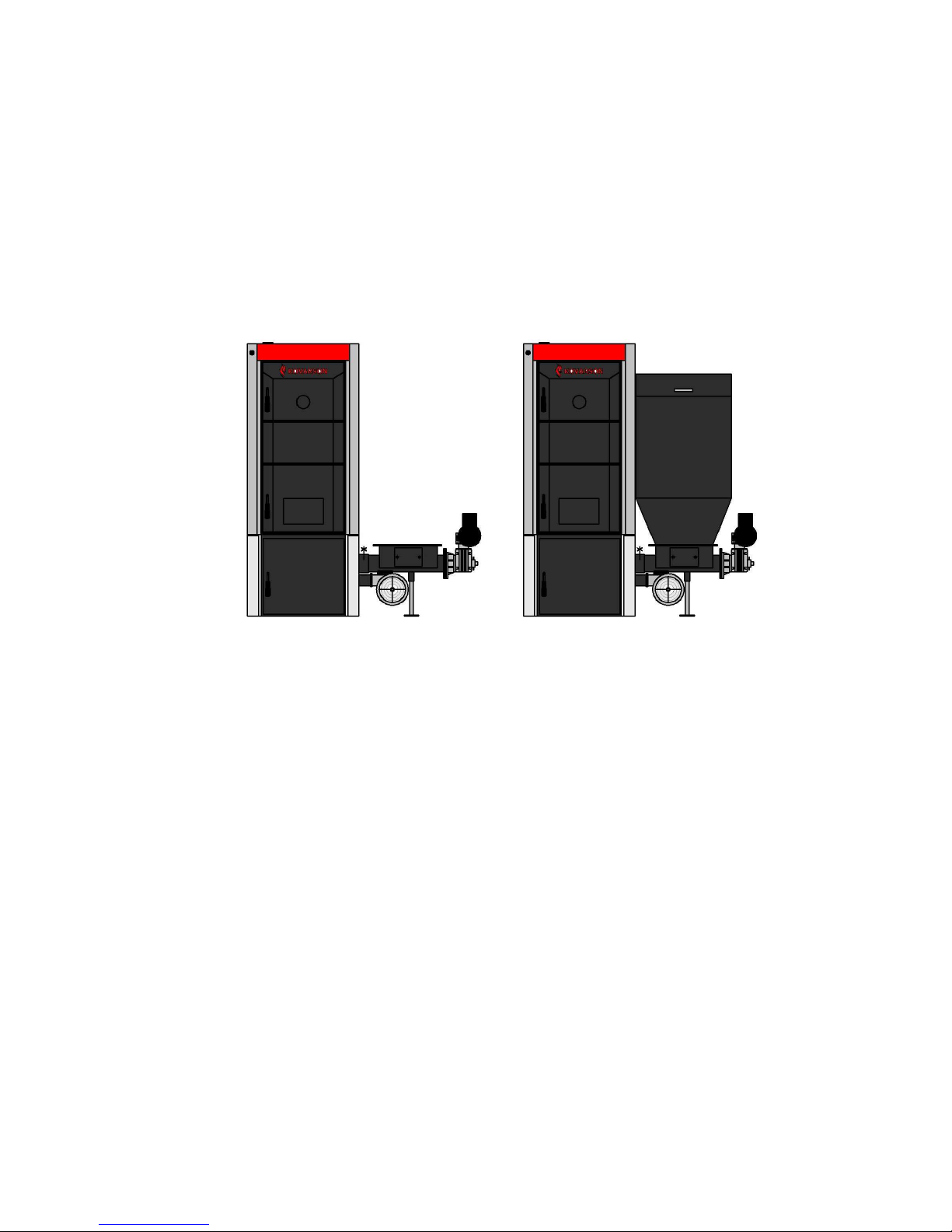
The screw feeder is placed next to the covered fuel hopper. Boilers can be ordered in
two variations:
• right fed – The fuel hopper is on the right side of the boiler body from the front
perspective
• left fed – The fuel hopper is on the left side of the boiler body from the front
perspective
There is wax plug inside the burner, which is the emergency extinguisher.
The boiler body, base and doors are insulated with non-toxic mineral insulation to
minimize heat transmission losses to the surroundings.
Page 8
- 8 -
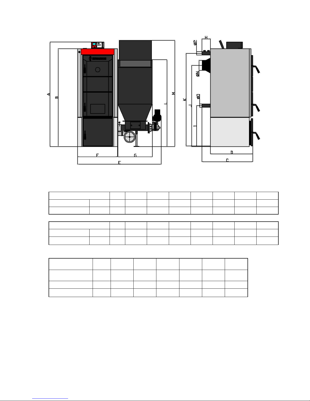
Figure1 Main boiler dimensions (right fed)
A B C D E F G H
dimension
4-7čl
1530 1445 1245 600 500 147
mm
8-10čl
1630 1545 1295 600 500 147
I J K L M N O P
dimension
4-7čl
620 1225 1400 1350 1710 158 2" 2"
mm
8-10čl 720 1325 1500 1450 1810 178 2" 2"
Boiler
TIGER
20
TIGER
25
TIGER
30
TIGER
35
TIGER
40
TIGER
48
TIGER
55
Number of
sections
4 5 6 7 8 9 10
C 493 603 713 823 933 1043 1153
D
640 750 860 970 1080 1190 1300
Page 9
- 9 -
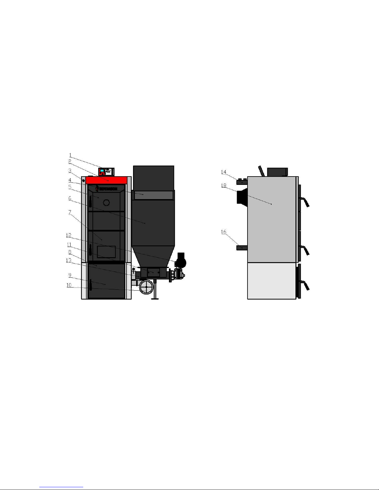
1. LIDER control unit
2. boiler cover
3. flue damper
4. fuel hopper cover
5. top cleaning door
6. fuel hopper
7. middle door
8. base
9. lower door
10. fan
11. fuel hopper cleaning plate
12. feeder motor
13. fuel feeder
14. output of heating water
16. input for heating water
18. boiler body
Page 10

- 10 -
4.2
Control, regulation and safety elements
The LIDER electronic control unit manages and controls the system - see separate
manual.
Safety elements:
• An emergency heating system thermostat safeguards against overheating. It is set
at 90° C by the manufacturer, above which temperature the fan shuts down for a
certain time while the feeder works in cycles to smother the fire.
• A fuel tank temperature sensor safeguards the system against fuel back-burn. The
factory setting is at 70°C, but the user may reset the temperature according to
his/her needs. If the temperature is higher than the setting, the feeder motor is
started up according to the time set in the control unit to smother the fire. This
function is only available if the boiler is connected to a power source.
• There is an overheating safeguard for the motor. The normal operating temperature
is anything below 80°C.
• Fire extinguishing equipment is included as an element of the safety system in case
of back-burn. The system is triggered if the wax plug is melted – this happens if the
temperature in the feeder exceeds 90°C. Water will be released from the plastic
tank.
4.3 Boiler accessories
Standard accessories:
• Boiler operation and installation manual
• Control unit manual
• 2 ceramic top tiles ( 2 tiles)
• Ash pan
• Ash brush
• Poker
• emergency fire extinguisher with wax plug
• 2 flanges (upper and lower)
• 2 ¾” plugs
• fill/drain valve
• 2 shear fuses
• 2 reservoirs for sensors
Page 11

- 11 -
5. Location and installation
5.1 Regulations and Requirements
The solid fuel boiler is only to be installed by heating specialists with a valid license for
the installation and maintenance of such equipment. The installation project must be
undertaken according to valid regulations.
The heating system must be filled with water that meets ČSN 07 7401 requirements
and, in particular, its mineral content must not exceed the maximum parameters.
Recommended values
Hardness mmol/l 1
Ca2+ mmol/l 0,3
Total Fe & Mn concentration mg/l (0,3)*
CAUTION!!! The manufacturer does not recommend the use of antifreeze.
a) About the heating system
ČSN 06 0310 Heating systems in buildings - Design and installation
ČSN 06 0830 Heating systems in buildings – Safety equipment
ČSN 07 7401 Water and steam for thermal energy equipment with
working pressure up to 8 MPa.
ČSN EN 303-5 CH boilers – Part 5: CH boilers for solid fuel with manual or
automatic delivery, nominal heat output of up to 300 kW –
Terminology, requirements, testing and marking.
b) About the chimney
ČSN 73 4201 Designing chimneys and flues.
c) Due to fire regulations
ČSN 06 1008 Fire safety for heating equipment.
ČSN EN 13 501-1+A1 Fire hazard classification: Buildings and construction
Buildings - Part 1: Classified from results of reaction to fire
d) The power supply
ČSN 33 0165 Electrical regulations. Marking of wires with colours or
numbers. The implementing regulations.
ČSN 33 1500 Electro-technical regulations. Testing of electrical devices.
ČSN 33 2000-3 Electro-technical regulations. Electrical devices. Part 3:
Declaration of the basic characteristics.
ČSN 33 2000-4-41 Electrical devices: Part 4: Safety Section 41: Protection
against electric shock.
ČSN 33 2000-5-51 ed. 2 Electro-technical regulations. Construction of electrical
devices.
ČSN 33 2130 Electro-technical regulations. Indoor electrical wiring.
ČSN 33 2180 Electro-technical regulations.
Connection of electrical
devices and appliances.
Page 12

- 12 -
ČSN 34 0350 Electro-technical regulations.
Regulations for mobile
connections and cable placement.
ČSN EN 60 079-10 Electro-technical regulations. Regulations for electrical
equipment in potentially explosive areas with flammable
gases and vapours.
ČSN EN 60 079-14 ed.2 Electrical apparatus for explosive gas atmospheres - Part
14: Electrical installations in hazardous areas (other than
mines).
ČSN EN 60 252-1 AC motor capacitors - Part 1: General - Performance,
testing and rating - Safety requirements - Guide for
installation and operation.
ČSN EN 60 335-1 ed.2 Electric appliances for household and similar purposes -
Safety - Part 1: General requirements.
ČSN EN 60 335-2-102 Electric appliances for household and similar purposes
Safety - Part 2-102: Specific requirements for appliances
burning gas, oil and solid fuel and containing electrical
connections.
ČSN EN 60 445 ed. 3 Basic and safety principles for man-machine interface,
marking and identification.
ČSN EN 60 446 Basic and safety principles for man-machine systems –
Identification of conductors by colours or numbers.
ČSN EN 61000 – 6 –3 EMC Part 6-3: Generic standards - Emission - for residential,
commercial and light industry.
ČSN EN 61000 -3 – 2 EMC - Part 3-2: Limits - Limits for harmonic current emissions
(equipment input current up to and including 16).
ČSN EN 61000 – 3 –3 EMC – Part 3 - Limits - Section 3: Limitation of voltage
fluctuations and flicker in low-voltage supply systems for
devices with nominal current <16A.
e) About the DHW heating system
ČSN 06 0320 Heating systems inside buildings – DHW set-up –
Design and planning.
ČSN 06 0830 Heating systems inside buildings – Safety equipment.
ČSN 73 6660 Indoor water systems
5.2 placement options
The boiler can be installed and operated in a simple environment AA5/AB5 according
to CSN 33 2000-3. The boiler is equipped with a portable power cable and plug. The
boiler must be in compliance with EN 60 335-1 ed. 2 Article 7.12.4, positioned so that
the plug is accessible.
The installation and use of the boiler must comply with all ČSN 06 1008
requirements.
Page 13

- 13 -
Location of the boiler in conformance to fire regulations:
1. Positioning on a floor made of non-combustible material:
• The boiler is to be set on a non-combustible insulating mat exceeding the
dimensions of the boiler by 20 mm on all sides
• If the boiler is located in the basement, it is recommended that it be placed it on a
base at least 50 mm high. The boiler must stand horizontally level; any unevenness
in the substructure is eliminated using the screws under the fuel hopper.
2. Safe distance from combustible materials:
• when installing and operating the boiler a safe distance of 200 mm is to be
maintained from combustible materials
• For highly flammable materials that can ignite quickly and sustain combustion after
the source of ignition has been extinguished (e.g. paper, paperboard, cardboard,
asphalt and tarpaper, wood and fibreboard, plastics, floor coverings), the safe
distance is doubled to 400 mm.
• When in doubt about the combustibility of materials the clearance should be doubled
(i.e. 400mm).
Operating clearance:
• Roughly 1000 mm should be allowed for front clearance.
• The rear of the boiler must clear the wall by 400mm
• 1000 mm should be allowed for clearance on the hopper side in case the feeder
screw needs to be removed.
• There should be at least 450 mm of clearance space above the boiler.
Electrical outlet and boiler placement:
• The boiler must be positioned so that the electrical outlet (230 V/50 Hz) is always
accessible.
Location of fuel
• Dry fuel must be used for proper combustion. The manufacturer recommends that
fuel be stored a cellar or under shelter
• Do not store fuel less than 400 mm from the boiler.
• The recommended minimum distance between the boiler and fuel is 1000 mm or
storage in separate room
Page 14

- 14 -
There must be a
continuous supply of air for combustion and ventilation in the boiler
room.
Tab.6 – Air consumption
Boiler model
TIGER
20
TIGER
25
TIGER
30
TIGER
35
TIGER
40
TIGER
48
TIGER
55
Number of sections
4 5 6 7 8 9 10
Air consumption [m3.h-1]
45 60 75 90 105 120 135
All heating pipes must be installed by authorized personnel.
CAUTION: When connecting the boiler to the heating system the fill / drain valve must
be placed as close as possible to the boiler.
Figure2 Placement of the boiler
Page 15

- 15 -
6. Boiler installation
6.1 Packaging and accessories
The boiler is delivered disassembled on 2 pallets. Accessories are shipped inside
boiler body. Open the cleaning door to remove them. The base for the burner, the
universal burner, the control unit, the fan, the fuel hopper and complete metal plating
with mineral fibre insulation are delivered on the second pallet.
Standard boiler delivery:
− 1 boiler on a palette in the particular number of sections
− The boiler casing with mineral fibre insulation
− 1 ash pan
− Cleaning tools (scraper, brush with handle, poker, 2 wall plugs, 2 threaded hooks)
− 1 thermo-manometer
− 1 1/2” fill/drain valve
− 1 6/4” end plug
− 2 seals (φ 60 x 48 x 2)
− 1 rod with handle to manipulate the damper
− 1 damper label
− Assembly hardware for the boiler body shell (4 spring clips, 4 connection pins, 16
8x13 ST4 bolts)
− Two 2" heating and returning water flanges (for sizes 4-7); one hot water flange
(for sizes 8-10); and one “Y” pipe for returning water with flange
− 2 seals φ 90 x 60 x 3
− adjustment wrench
− technical and sales documentation
− LIDER control unit with temperature sensors and connectors
− fan with relevant output
− universal burner with relevant output
− One telescoping leg
− Assembly hardware for the burner and the base (four M12x30 bolts, four M12
nuts)
− stove sealant (1 tube)
− plastic ties for binding control unit cables
− 2 ceramic upper tiles
− One ½”- end plug
− 4 turbulators
− base covering
− fuel hopper
− boiler base
− assembly hardware for fan (four M6x30 bolts, four M6 nuts)
− assembly hardware for fuel hopper (six M8x30 bolts, six M8 nuts)
− rubber fan mat
− rubber fuel hopper mat
Page 16

- 16 -
− two HEYCO grommets
−
extinguishing system (one plastic tank, 3/8” 1 m hose, hose connector, 12mm
compression fittings, two wax plugs)
− extinguishing system bracket
− assembly hardware for extinguishing system (two M6x10 flush-head screws, two
M6 nuts)
− four tensioners (Ø8 mm)
− two ¾” plugs
− two thermo-reservoirs
6.2 Installation procedure
6.2.1 Installation of the boiler body and base
1. Position the boiler body with the retaining wall at the base pad in a horizontal
position.
2. Fill the space between the base and the boiler with sealant.
3. Connect the boiler’s smoke outlet to the flue pipe in the chimney with a 160mm flue
pipe.
4. Plug the 1 ½” threaded holes in the front section of the boiler with plugs. Seal each
plug with an O-ring.
5. Plug the ½” threaded holes in the front section of the boiler with plugs. Seal each
plug with an O-ring.
6. Open the cleaning door and insert upper fire bri
Obr. č. 6 Sealing base
6.2.2 Mounting the casing
Boiler casing
1. Remove the casing components from box.
2. Fit the sheet metal components with the appropriate fasteners (see Figure 6 - 10
bolts - ST 4.8 x 13).
3. Assemble the boiler casing (see Figure 6)
4. Assemble the left and right casing components on the anchoring bolts and then
add the front part of the casing. Bolt the rear part to the sides. On the side parts
put the front seat with the inscription. Insert the thermo-manometer and capillary
tubes into the upper part of the shell, leading to the recovery valve up the isolation
Page 17

- 17 -
upper part of the shell. Care must be taken so that the capillary tubes do not touch
the boiler body.
Figure 6 Boiler body casing
Base casing:
1. Remove the casing from the carton.
2. After screwing the burner head on, hook the side burner base casing onto the boiler
casing. Add the rear of the casing and tighten the screws.
Page 18

- 18 -
6.2.3 Burner Installation
1.
Screwed the cast iron burner head onto the base.
2. Remove the cast iron collar from the cast iron head
3. Seal the flange burner head
4. Put the universal burner into the base without the collar and tighten the bolts
5. Use stove sealant on the collar and put it back (Figure 8)
6. Join the burner screw and shorten the leg as required. It must correspond to the
red mark.
Figure 8 Sealing the top cast-iron collar and flange
6.2.4 Fan installation
1. Put the fan in place and bolt it on.
Figure 9 Fan installation
Page 19
- 19 -
6.2.5 Fuel hopper installation
1.
When assembling the fuel feeder to the base and to the fuel hopper, first ensure
that everything is level and then final tighten the bolts.
2. Apply sealant to the fuel screw feeder where the contact surfaces of fuel hopper
are to be placed. Put the fuel hopper in place and tighten the screws
Figure 10 Fuel hopper installation
6.2.6 Installation of control unit and temperature sensors
1. Place the control unit on the boiler.
2. Engage temperature sensors:
• Put the CH sensors into the reservoirs in the boiler’s water output connection
• The DHW sensor is placed into the boiler reservoir or taped directly onto the
pipe (the sensor is set to OFF in the factory settings, the sensor is only used
when the boiler is in use)
• The temperature regulation sensor (an emergency thermostat) is put into a
separate reservoir in the boiler’s water output pipe, as close to the boiler as
possible
• The hopper temperature sensor is put into a pipe placed on the screw feeder
behind the fan
3. Connect the feeder, fan and pumps according to the control unit instructions.
6.2.7 Installation of emergency fire safety equipment
1. Remove the silver-coloured plug from the burner.
2. Screw in the copper hose connector
3.
Put one end of the hose onto the hose connector and tighten the hose clamp.
4. Cut the hose to the desired length.
Page 20

- 20 -
5.
Fasten the other end of the hose to the tank’s tap nozzle and tighten the hose
clamp.
6. Install the water tank in the bracket at the back side of the hopper.
7. Operating the boiler by the user
Only authorized heating specialists are to put the boiler into service.
Figure12 Boiler connection dimensions
Boiler A B C
4 - 7 section 620 1225 1400
8 – 10 section 720 1325 1500
7.1 Electrical Wiring
It is not necessary to interfere with the electrical wiring in any way when putting the
boiler into operation. All the connectors are connected to the rear of the control unit;
these connectors allow for quick and easy connection to, or disconnection from, the
control unit.
Shorten or extend sensor cables abiding by the following recommendations:
• Do not cut the sensor cables to a length shorter than 0.5m
• We do not recommend extending the sensor cable more than 10m
• CMSM - H 2 x 0.5 mm cable is recommended for extensions
• Take care in extending cables. When shortening or extending a cable ensure
there is a good connection.
Page 21

- 21 -
7.2
Pre-fire-up check list
Before firing up the boiler the following should be checked:
a) Heating system water level
The mineral content (hardness) of the water used in the boiler must comply with ČSN
07 7401 standards and it is essential that, if the mineral content is not in compliance,
the water must be softened – this is covered in Section 05.01. Heating systems with
open expansion tanks allow direct contact between the water and air in the
environment. During the heating season the expanding water in the tank absorbs
oxygen, which hastens the effects of corrosion while allowing significant water
evaporation. If more water is added, it must be treated according to ČSN 07 7401
standards.
The heating system must be thoroughly rinsed out in order to eliminate all impurities.
During the heating period a constant volume of water in the heating system must be
maintained. When adding water to heating system, it must be ensured that no air is
drawn into the system. Water from the boiler and heating system must never be
discharged or removed except in cases of emergency such as repairs etc. Draining the
water and replenishing it increases the risk of corrosion and scaling. If it becomes
necessary to add water to the heating system, do so only when the boiler is cold to
avoid cracking.
b) A tight heating system
c) Connecting the flue – The flue must be approved by a chimney inspector
d) Burner tightness
Connect to the power supply (insert the plug into the socket). Switch on the control unit
using the main power switch, change the mode to manual feeding and start up the fan.
Air must flow only into the combustion chamber in the universal burner. Focus on the
following contact surfaces when performing the system check:
− Between the fan and flange
− Around the lower burner ash pit
− The cast iron grate fitting. If there appears to be leakage, remove the grate and the
sealant, reapply an appropriate amount of new sealant, refit the grate and check the
fitting again.
− The fan will switch off when the button is pressed.
e) Connection to main power supply
Power is supplied through a flexible cable plugged into a standard 230 V/50 Hz/10 A
wall socket.
g)
Check the flue damper opening
Page 22

- 22 -
7.3 Control unit parameters setting
Tab.7 control unit set to brown coal at nominal output
Boiler model
TIGER
20
TIGER
25
TIGER
30
TIGER
35
TIGER
40
TIGER
48
TIGER
55
Number of sections
4 5 6 7 8 9 10
Feeding time 12 14 6 6 6 6 5
Feeding idle time 30 25 12 7 5 20 15
Fan speed 22 30 35 39 45 28 30
Minimum speed - SERVIS 20 20 20 20 30 20 30
Maximum speed - SERVIS 52 52 52 51 55 43 43
Tab.8 control unit setting for brown coal at reduced power
Boiler model
TIGER
20
TIGER
25
TIGER
30
TIGER
35
TIGER
40
TIGER
48
TIGER
55
Number of sections
4 5 6 7 8 9 10
Feeding time 5 5 6 7 7 5 5
Feeding idle time 54 48 41 34 30 68 60
Fan speed 25 26 28 31 34 10 15
Minimum speed- SERVIS 20 20 20 20 20 20 20
Maximum speed- SERVIS 36 40 45 45 45 20 20
Tab.9 Control unit setting for wood pellets at nominal heat output
Boiler model
TIGER
20
TIGER
25
TIGER
30
TIGER
35
TIGER
40
TIGER
48
TIGER
55
Number of sections
4 5 6 7 8 9 10
Feeding time 6 7 8 9 12 6 5
Feeding idle time 10 9 8 6 5 14 8
Fan speed 23 28 33 38 43 28 32
Minimum speed- SERVIS 20 20 20 20 20 30 30
Maximum speed- SERVIS 51 51 51 51 51 50 50
Tab.10 Control unit setting for wood pellets at reduced power
Boiler model
TIGER
20
TIGER
25
TIGER
30
TIGER
35
TIGER
40
TIGER
48
TIGER
55
Number of sections
4 5 6 7 8 9 10
Feeding time 8 8 8 8 8 5 5
Feeding idle time 66 59 41 34 28 53 45
Fan speed 13 15 16 18 20 8 10
Minimum speed- SERVIS 21 20 20 20 20 20 20
Maximum speed- SERVIS 28 30 50 51 50 20 20
Page 23

- 23 -
7.4
Putting the boiler into operation - Firing up
1. Firing up
− Check parameter settings - see Section 7.3
− Check the amount of water in the heating system using the manometer.
− Open the closed valves between the boiler and heating system.
− Check that the pumps are in order (i.e. are they turning?)
− Clean the burner and ash pan (not for the first firing). The ash door must be shut at
all times when the boiler is being fired up and when it is in operation.
− Fill the fuel hopper with the appropriate amount of fuel. After filling the fuel hopper,
close it tightly to prevent possible air intake into the burner through the feeder.
− Switch the unit on in manual mode and start feeding the feeder using the “+ button”.
The fuel must be fed into the burner to approximately 1 cm below the edge. The
feeder will feed the burner for approximately 7 minutes. If the motor gets too hot, the
thermo-fuse will cause the feeder to stop. After cooling, the motor begins feeding
again.
− The fuel should be ignited with liquid or solid fire starters, or with wood chips.
− Ignite and let it burn.
− Allow to burn for about 3 minutes, then gradually start the fan by pressing the “-
button”. In the beginning, start the fan and then stop it. If the fan blows too hard in
manual feeding mode, the maximum fan speed needs to be set in the service menu.
− When firing up, keep the fuel level about 2 cm below the edge of the cast iron grate.
− When the space inside burner has completely heated up, the boiler can be switched
to automatic mode by pressing the ↑ button.
2. Recheck the tightness of the boiler.
3. Do a heat test.
4. Familiarize users with service.
5. Make a record in the warranty certificate.
Checking the shape of flame (brown coal or wood pellets)
The shape of the flame gives indicates whether the boiler settings are correct at
nominal output. It is recommended that a check be performed whenever new brown
coal has been purchased. When checking the shape of the flame, make sure the boiler
is set to nominal output.
Page 24

- 24 -
Brown coal nut 2:
Figure13
desired flame Figure14 poor flame
Wood pellets:
Figure15 desired flame Figure16 poor flame
Page 25

- 25 -
7.5 Using a thermostat to optimize performance
A LIDER control unit can be connected using a remote thermostat. This allows the
user to access and set the boiler’s settings more easily and comfortably. Constant
comfort and regular heating conditions can be set in living areas. When the room is
heated to the desired temperature, the control unit switches to MONITORING mode,
whose primary function is to switch the circulation pump off for 25 seconds during
which time the THERMOSTAT LED is on. If the boiler is in MONITORING mode (i.e.
the fuel feeder and fan are off) and the temperature in the boiler reaches 80°C due to
an idle circulation pump, the LIDER control unit starts the pump up regardless of the
thermostat’s signals (i.e. the LIDER control unit will override the thermostat
signal).This helps to ensure that the boiler does not overheat.
However, if the temperature in the boiler falls below the minimum operating
temperature in the service setting, which is 40°C, the unit switches from
MONITORING mode to REGULATION mode and the boiler heats up back to the
desired minimum temperature with circulation pump off. When the thermostat detects
that the room temperature has decreased and needs to heat back up, the control unit
will switch back to REGULATION mode, the circulation pump will start up and the
boiler will heat the room to the thermostat setting.
Thermostats can be connected using a 2-wire cable according to the control unit’s
operation and installation instructions. The LIDER control unit comes with a cinchtype connector. The on-off switch in the thermostat communicates sends signals to
the LIDER control unit. No signal is sent when the desired room temperature is
higher than the temperature in the room. A signal is sent the moment the room
temperature dips to the temperature that has been set.
A wired or wireless thermostat can be used to regulate room temperatures.
Page 26

- 26 -
8. Important instructions
• The boiler can be used only for the purposes for which it is designed.
• The boiler may only be operated by adults familiar with these operating
instructions. Do not leave children unattended near the boiler when it is in
operation.
• The boiler is not intended for unsupervised use by children, by persons with
reduced physical, sensory or mental capabilities, or by those who lack the
experience or knowledge to the appliance safely, unless these persons have
been adequately instructed how use the appliance by a person responsible for
their safety. Children should be supervised to ensure that they do not play with
the appliance.
• If there is a risk that flammable vapours or gasses may enter the boiler room, or
if there is work being done during which there is a temporary risk of fire or
explosion (e.g. gluing floor coverings, painting with flammable paints, etc.), the
boiler must be shut down before beginning the operation. When fuel is being fed
into the combustion chamber before firing up, it should be checked visually – do
not insert hands into the firebox. There is a risk of injury caused by the rotating
the feeding screw.
• Do not use flammable liquids (gasoline, alcohol, etc.) when heating up the
TIGER boiler. It is FORBIDDEN to overheat the boiler in any way during
operation.
• Do not place flammable objects closer than the safe distance to the boiler.
When removing the ashes from the boiler a minimum distance 1500 mm must
be maintained for all flammable substances. The ashes must be disposed of in
a non-combustible container with a lid. Wear protective equipment.
• After the heating season the boiler should be thoroughly cleaned, including the
flue pipe. The boiler room must be kept clean and dry.
• Do not tamper with the boiler construction or electric components.
• A relief valve must be installed to the maximum overpressure of ..... kPa - the
value must match the boiler’s nominal output. If you have any questions, please
contact our installation partners or service agents.
• Poor fuel quality can significantly affect the performance and emission
parameters of the boiler.
• The rules and regulations of the applicable region must be adhered to during
assembly, installation and operation of the appliance. If these conditions are not
met, the warranty is void.
• By Czech Government regulation 91/2010 Sb. pertaining to fire safety for
chimneys, flues and fuel burners, the operator is obliged to undertake regular
cleaning and inspections.
Page 27

- 27 -
9. Maintenance
1. Ensure that the fuel hopper is constantly refilled. If the fuel level is too low, refill the
hopper. When adding fuel or checking the fuel level be sure to cover the hopper
tightly!
2. If the boiler is correctly adjusted the fuel is burned up by the time it reaches the
edge of the grate. The ashes then drop into the ash pan. On average, the ash pan
needs to be emptied every second day (use protective gloves when handling the
ash pan). Occasionally pieces of cinder need to be removed from around the edge
of the grate. Use the poker to do this.
3. When in continuous operation, it is recommended to clean the inner surfaces of
the boiler body twice a month (If not cleaned, heat transfer surfaces are adversely
affected, which can have a significant negative impact on the boiler’s heat transfer
efficiency).
4. The air intake mixer should be cleaned every 3 months. The mixer has an
influence on the correct airflow.
5. If a hard object gets stuck in the feeder screw causing the shear fuse to go, replace
the fuse. Clean the unwanted material from the screw through the hopper cleaning
opening and use a 19 mm wrench to rotate the screw. Then install a new fuse and
put the burner back into operation.
WARNING: Before performing this operation, make sure the boiler is
disconnected from the power supply (the plug is removed from the socket) and
fuel is cooled to avoid a back-burn.
6. There is a small amount of overpressure in the boiler because of the fan and,
therefore, it is necessary to ensure that the boiler is air-tight (e.g. the cleaning
doors, middle door, ash door, burner cleaning opening, fuel hopper cover, etc.).
Fuel hopper tightness achieved when the lid is properly shut and latched provided
that the surfaces of the rubber seal are undamaged. If the fuel hopper seal is
damaged, replace it.
7. In the event of a power failure, the wax cap acts as a safeguard against back-
burn and extinguishes burning fuel. Always keep the tank filled with water.
8. Clean the inside of the combustion chamber, the smoke outlets and fittings once
a month. Do not clean the boiler unless it is cooler than 40°C. Use the cleaning
hatch in the bottom to remove the ash from the flue fitting. Ensure that it is airtight
after cleaning.
Page 28

- 28 -
10. Disposal of the product after its life cycle
Packaging should be disposed of as follows:
• plastic wrappings, cardboard packaging can be discarded at a waste facility
• metal strapping can be discarded at a waste facility
• the wooden base is intended for a single use must be discarded. The disposal
of the base is subject to Act 94/2004 Coll. and 185/2001 Coll. as amended.
Because the boiler is manufactured from common metals, dispose of the individual
parts as follows:
• mixer (gray cast iron) can be discarded at a waste facility
• piping, shell can be discarded at a waste facility
• other metal parts can be discarded at a waste facility
11. Guarantee and liability for defects
The company provides the following guarantee:
The boiler is guaranteed for a period of 24 months from the date it is put into
operation.
For claims pertaining to the casing, the customer must submit the boiler casing
packaging label. It is located on the carton in which the casing is shipped.
The user must have a professional assembly service company put the boiler into
operation and service the equipment, otherwise proper functioning cannot be
guaranteed. A completed "certification of quality and completeness of the TIGER
boiler" document can be used as a “Certificate of warranty”. The user is obliged to
have the boiler undergo regular maintenance.
Defects should be reported immediately after detection in writing and by telephone.
Failure to follow these instructions will void the manufacturer’s warranty.
The manufacturer reserves the right to make changes related to product innovations
that may not be included in this manual.
The warranty does not cover:
- defects caused by improper assembly, improper handling or defects caused by
improper maintenance (more in Section 8)
- product damaged during transport or other mechanical damage
- defects caused by improper storage
- defects caused by failure to observe water quality guidelines for the heating system
(more in Section 5.1 and 7.2) or through the use of anti-freeze
- defects caused by not following the instructions provided in this manual.
- failures caused by operating the boiler on non-warrantied fuel (see Tab. 3 and 4)
Page 29

- 29 -
12. Trouble shooting
Issue
Possible cause
Resolution
control unit cannot
be turned on
- no voltage in the network
- check the power network
- plug incorrectly inserted in the wall
socket
- check the socket connection
- defective control unit
- replace the unit
- damage to the power cord
- replace the cord
- LED indicators do not light up
- replace
damaged fuse
boiler does not
reach the
required
parameters
- low water level in the heating
system
- refill
- pump output too high - adjust the flow rate and pump
switching
- Power output too low for the
system
- poorly prepared project
- poor quality fuel - check and heating value and
quality of materials from suppliers
- insufficient draft - new chimney, or correct improper
connection
- excess flue draft
- install a damper in the flue
- inadequately cleaned boiler
- clean the boiler
Door leaks
smoke
- improperly adjusted door hinges
- tighten the hinge screws
- faulty sealing cord
- replace the cord
Fan wobbles or is
noisy
- overheated boiler - temperature
limiter activation (an emergency
thermostat)
- wait until temperature drops to
approximately 70°C, then press the
temperature limiter placed on the
control unit
- inoperable motor
- replace the motor
- Damage to the power cord
- replace the cord
Alarm activation
- Alarm 5
- shortage of fuel
- improper adjustment of fuel
delivery unit
- alarm sensors - determine which sensor is
damaged and contact service
Smoke in the
boiler room
- leaky door
- replace the sealing cord
- Tighten the hinge screws
- Failure to set the burner - if boiler smokes, reduce the
amount fuel being fed or increase
fan speed
Page 30

- 30 -
EC DECLARATION OF CONFORMITY
by
Directive of the European Parliament and of the Council
2006/42/ES (
Government
Regulation No.
176/2008 Sb.)
by Directive of the European Parliament and of the Council 2006/95/ES (
Government
Regulation No.
17/2003 Sb.)
by Directive of the European Parliament and of the Council 2004/108/ES (
Government
Regulation No.
616/2006 Sb.)
Producer : KOVARSON s.r.o. Lhota u Vsetína 4, 755 01
Device: An automatic boiler for burning brown coal or wood pellets
type code: TIGER 20, TIGER 25, TIGER 30, TIGER 35, TIGER 40, TIGER 48, TIGER 55
Description of the device:
Automatic cast iron boiler with fuel feeder and fuel hopper. Brown coal “nut 2”
or wood pellets used as fuel.
meets the requirements of:
Directive 2006/42/ES (Government Regulation No.176/2008 Sb.)
Directive 2006/95/ES (Government Regulation No.17/2003 Sb.)
Directive 2004/108/ES (Government Regulation No.616/2006 Sb.)
List of other technical standards and regulations:
ČSN EN 303-5:2000, ČSN 06 1008:1997, ČSN EN 60335-1:2003 ed. 2, ČSN EN 60335-2102:2007,ČSN EN 55014-1:2007 ed.3, ČSN EN 61000-6-3:2007 ed.2, ČSN EN 61000-3-2:2006
ed.3, ČSN EN 61000-3-3:2009 ed. 2, ČSN EN 55014-2:1998, ČSN EN 62233:2008, ČSN EN ISO
2100:2011, ČSN EN 953+A1:2009, ČSN EN ISO 11202:2010, ČSN EN ISO 3746:2011
ČSN ISO/TR 9172, ČSN ISO 1819:1993
Person responsible for assembling the technical documentation:
Ing. Jan Valčík
Person authorized to draw up the original EC declaration of conformity:
Bc. Jaroslav Kovář
The manufacturer declares that the equipment fulfills all the relevant
provisions of the present regulations of the European Community.
This declaration of conformity is the original EC declaration of conformity.
The last two digits of the year in which the CE marking was affixed: 10
In Vsetíně day 10.10.2012
................................................... ..................................................
Person responsible for the preparation authorize the signatory on behalf of the
original EC declaration of conformity manufacturer
, or authorized representative
Page 31

- 31 -
Page 32

- 32 -
KOVARSON s.r.o.
Lhota u Vsetína 4
755 01, Vsetín
Tel. ČR: +420 571 420 926
Tel. SR: +421 949 176 717
Email: info@kovarson.cz
 Loading...