

Page 1
KOVARSON s.r.o.
Lhota u Vsetína 4
755 01, Vsetín
tel. ČR: +420 571 420 926
tel. SR: +421 949 176 717
email: info@kovarson.cz
Manual for combi boiler
PREDATOR
Page 2

Dear customer,
Thank you for purchasing pyrolytic boiler MAKAK and the trust you have put in
KOVARSON s.r.o.
The boiler you have purchased has been comprehensively tested by our development
department and. We believe that you will be satisfied with our product. To avoid any
problems, we advise you to read carefully the installation manual of the boiler, before you
start using it.
If you have any questions, please do not hesitate to contact our service engineers who will
help you with your inquiries and always resolve your issue quickly.
Comfortable heating by
KOVARSON s.r.o.
- 2 -
Page 3

Content
1) Boiler application and benefits ................................................................................... - 4 -
2) Boiler description ..................................................... Chyba! Záložka není definována.
2.1 Boiler construction ............................................... Chyba! Záložka není definována.
2.2 Function parts of boiler ................................................................................................ 6
2.3 Boiler accesories ................................................... Chyba! Záložka není definována.
3) Technical parameters ................................................ Chyba! Záložka není definována.
4) Recommended fuel ................................................... Chyba! Záložka není definována.
5) Boiler installation ..................................................... Chyba! Záložka není definována.
5.1 Rules and regulations ................................................................................................. 11
5.2 Placement options ................................................. Chyba! Záložka není definována.
5.3 Connecting the boiler to the chimney and outlet of combustion products ....... Chyba!
Záložka není definována.
5.4 Air supply to the boiler ......................................... Chyba! Záložka není definována.
5.5 Connecting the boiler to the heating system .............................................................. 14
5.6 The cooling loop connection ................................ Chyba! Záložka není definována.
5.7 Connection to the mains ....................................... Chyba! Záložka není definována.
5.8 Boiler parts installation ......................................... Chyba! Záložka není definována.
5.8.1 Installation of the boiler casing and thermostatic valve ........................................... 16
5.8.2 Exhaust fan connection ............................................................................................. 16
5.8.3 Universal burner connection ..................................................................................... 17
5.8.4 Fan and screw feeder installation ............................................................................. 17
5.8.5 Installation of the tank .............................................................................................. 17
5.8.6 Control unit FOX installation .................................................................................... 18
6 Boiler operation by user ................................................................................................ 18
6.8 Verification activities before usage of the boiler .. Chyba! Záložka není definována.
6.9 Firing ......................................................................................................................... 19
6.10 Stoking .................................................................. Chyba! Záložka není definována.
6.11 Combustion control ................................................................................................... 21
6.12 Power settings and regulation .................................................................................... 22
6.13 Ash removal .......................................................... Chyba! Záložka není definována.
6.14 Boiler cleaning ........................................................................................................... 23
6.15 Maintance and inspection of the boiler ...................................................................... 23
7 Control unit FOX .......................................................................................................... 24
7.8 Control unit FOX description .................................................................................... 24
7.9 Operation of the controller ................................... Chyba! Záložka není definována.
7.10 Temperature sensors installation .......................... Chyba! Záložka není definována.
7.11 Technical data ....................................................... Chyba! Záložka není definována.
7.12 A wiring diagram of the controller ............................................................................ 26
7.13 Commissioning .......................................................................................................... 26
8 Important alerts ............................................................................................................. 27
9 Disposal of the product after its service life .................................................................. 27
10 Warranty and liability for defects .................................................................................. 28
11 Warranty does not cover ............................................................................................... 28
11 Trouble shooting ........................................................................................................... 28
12 Recommended connection of the boiler ........................................................................ 30
- 3 -
Page 4

EC DECLARATION OF CONFORMITY .............................................................................. 31
1) Boiler application and benefits
Czech boiler PREDATOR is designed for economical and ecological heating of family
houses, business premises and medium – sized objects, including the ability to heat the water.
2) Boiler description
2.1 Boiler construction
The boiler is based on the principle of two-stage combustion at a high temperature
during a process is a wood gasification followed by combustion flue gases with an exhaust fan
which exhausts gases from the boiler. Universal burner is placed under the boiler for brown
coal combustion.
Boiler PREDATOR is welded boiler plate of high quality. The upper internal part of
the boiler consists of a fuel hopper, which is at the bottom equipped with a heatproof pipe
fitting having an elongated hole for the passage of gases. In the space below the fitting is a
burn-out area and below this ares is placed universal burner, below burner is an ashtray. At
the rear of the vertical flue gas heat exchanger which is in the upper part of the collecting
channel through which cold gases coming into the chimney.
Most strongly stressed part of the boiler by a high temperature, corrosive gases, acids
and condensates is the upper chamber, which is equipped with stainless steel inserts, which
protects the combustion chamber of the boiler and increases the durability of the boiler.
The inner part of the boiler is made of sheet metal with a thickness of 6mm, flue gas
heat exchanger at the back of the boiler is constructed by 5-exchanger tubes with inner
diameter of 6mm. The boiler has double casing, the inner part is made of 6 mm high quality
steel and any areas which might be in contact with the flame are reinforced by 8mm plate.
The outer part of the boiler is made from metal sheet 4mm.
In front of the boiler are upper stoking door, middle cleaning (ignition) door, bottom
cleaning (ignition) door and bottom door for the ash.
On the back of top boiler cover is a removable casing under which you will find
cleaning access for flue gas chamber. On the side of the boiler is located a handle for cleaning
turbulators.
The feeder shaft extends into the burner, where it is fastened on the far side. The screw
feeder extends to the combustion chamber and pushes against a counter screw, which forces
the fuel upwads.
The upper part of the burner is made of two cast iron rings.
The burner is fed air by a fan placed on the flange of the burner under the fuel hopper.
The fan can be regulated electronically.
The screw feeder is placed next to the covered fuel hopper. Boilers can be ordered in
two variations:
• Right fed – The fuel hopper is on the right side of the boiler.
• Left fed – The fuel hopper is on the left side of the boiler.
There is wax plug inside the burner, which is the emergency extinguisher.
- 4 -
Page 5
The boiler body, base and doors are insulated with non-toxic mineral insulation to
minimize heat transmission losses to the surroundings.
The body is insulated with mineral wool 40 mm thick and shielded by metal plating.
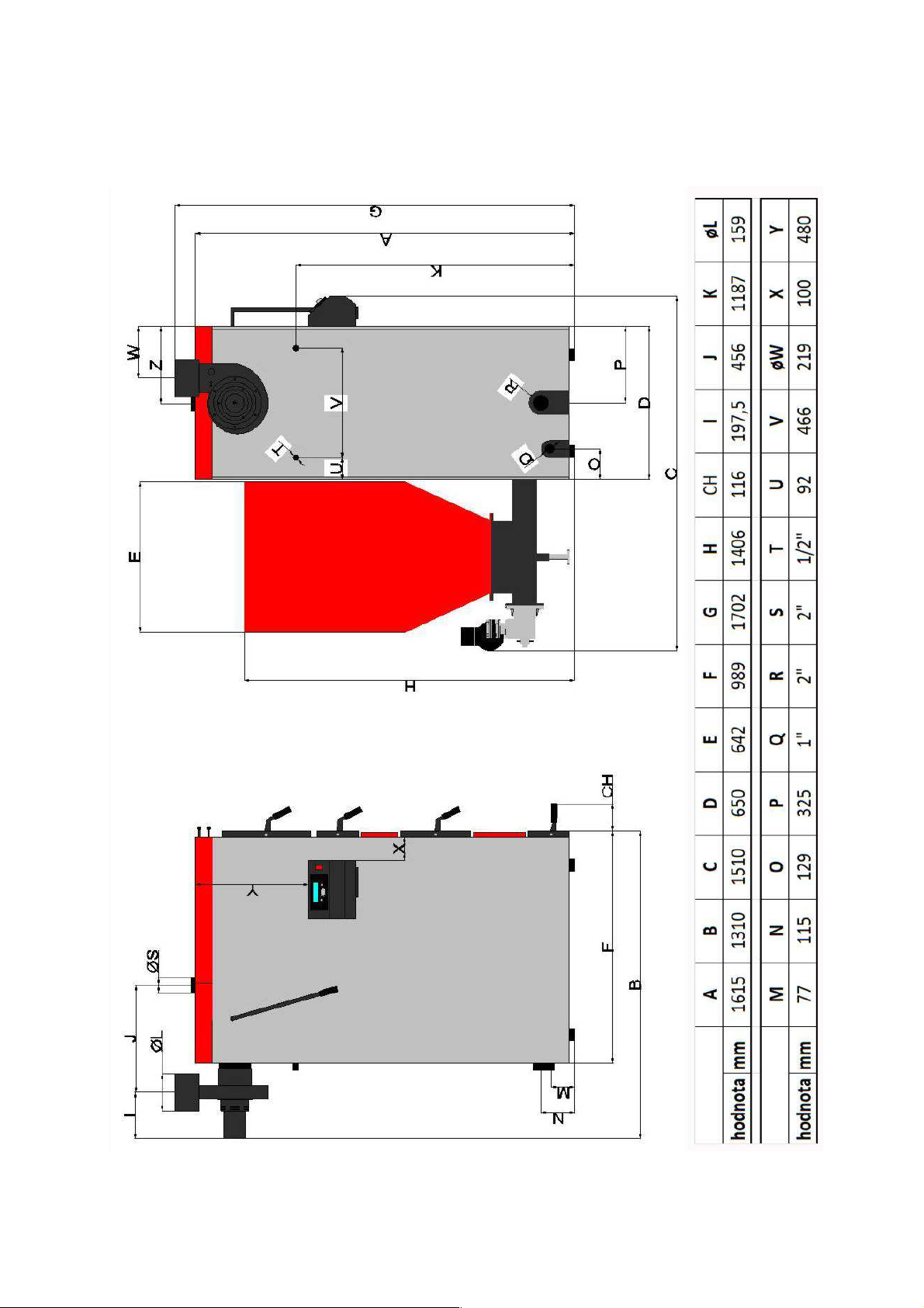
Pic. No. 1 Main boiler dimensions
- 5 -
Page 6
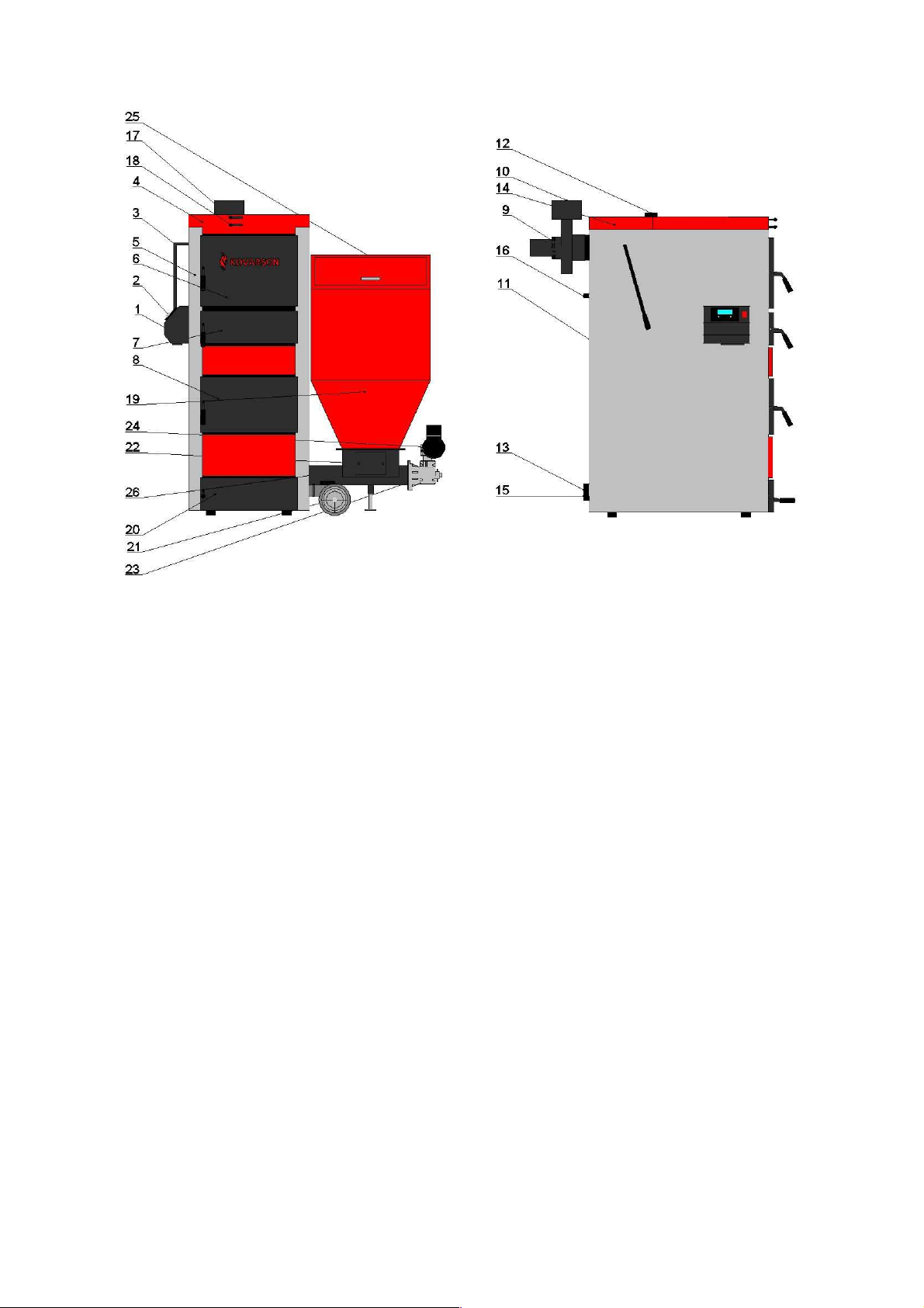
Pic. No. 2 Main parts of the boiler
1) Control unit display
2) Control unit
3) Handle for cleaning
4) Upper casing
5) Side Casing
6) Stoking door
7) Cleaning door
8) Middle door - burner
9) Exhaust fan
10) Flue outlet
11) Back casing
12) Heating water inlet
13) Drain valve
14) Top cover – heat exchanger
15) Heating water outlet
16) Cooling loop, waste connection
17) Primary air intake
18) Secondary air intake
19) Hopper
20) Ash door
21) Fan
22) Cleaning tank lid
23) Gearbox
24) Engine
25) Tank lid
26) Screw feeder tube
2.2 Function parts of boiler
Filling chamber – here is the primary combustion (gasification) process and it also serves as
the fuel hopper.
Refractory concrete fitted with nozzle – intake of secondary air to the nozzle.
Post - combustion area – there is a secondary combustion process and area which serves for
the collection of ash.
Main tube exchanger – transmitting the heat from the flue gases to heated water.
Fan – blows the air which is required for the combustion process, divided into:
a) Primary – air intake to the filling chamber supports the primary combustion.
b) Secondary – air intake into the nozzle is mixed with the woodgas.
Antismoke flap – system using a flap which draws smoke when you open the filling door.
- 6 -
Page 7
Universal burner – combustion of the brown coal supported by a fan.
Fan – supports combustion of fuel in the universal burner.
Fan flap – must close this valve during manual heating to avoid sucking air through the
burner.
Hopper – reservoir volume 350 liters.
Vermiculite plates – during the manual heating it is neccesary to place this plates above the
burner.
Boiler regulation – regulates the amount of air using the fan speed control, regulates the
efficiency of the boiler on the basis of the output temperatures. Controls pump and mixing
valve + it can also monitoring the storage tank.
Heatexchanger turbulators – additional device, which is located in the rear exchanger tubes.
Turbulators increasing efficiency and simplify cleaning of the boiler.
Cooling loop – The loop should be permanently connected to a water order and to the waste.
This system is monitoring a temperature using a bimetallic sensor to prevent overheating of
the boiler. In case that the boiler is overheated system is able to cool him quickly.
2.3 Boiler accesories
The boiler is delivered with the following accessories:
Steel brush 1pc
Scraper 1pc
Exhaust fan 1pc
Flange 2pc
Boiler manual 1pc
Manual FOX 1pc
Filling valve 1pc
Fan VPA06 1pc
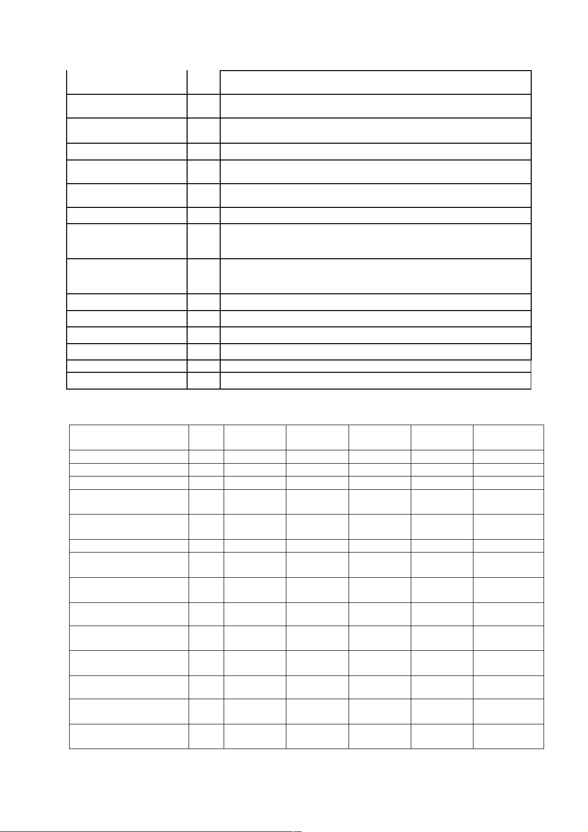
3) Technical parameters
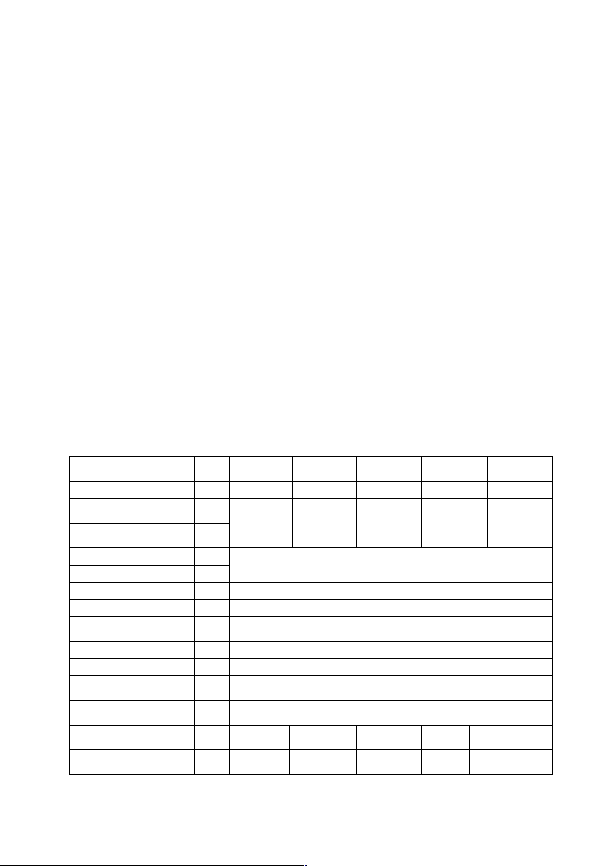
Chart, No. 1 – Dimensions and technical parameters of the boiler
PREDATOR
Boiler Type
Wood efficiency %
Coal efficiency –
nominal power %
Coal efficiency –
Minimal power %
Weight kg 750
Water volume l 140
Flue diameter mm 156
Combustion chamber depth mm 550
Combustion chamber
volume
Coal hopper volume dm3 350
Boiler dimensions mm See Figure 1
Size of hopper loading
window
Size of coal hopper loading
window
EN 303-5 boiler class wood
EN 303-5 boiler class –
brown coal
dm3 135
mm 440x300
mm 370x335
- 4 5 5 5 5
- 4 4 4 4
20
84,9 86,2 87,5 88,8 90,25
86,23 87,16 88,1 89,96
68,47 68,47 68,47 68,47
PREDATOR
25
PREDATOR
30
PREDATOR
35
PREDATOR
40
- 7 -
Page 8
-
1
Maximum operating
excess water pressure
Tested operating excess
water pressure tolerance
Recommended operating
tem. of heating water
bar 2
bar 2
°C 50-85
Hydraulic boiler loss mbar
Recommended operating
temp. of heating water
Minimum temperature of
returning water
°C 70 - 90
°C 55
Noise level dB < 60
Chimney draft during the
exhaust fan running at a
rated power
Pa
20
Boiler connections - water
heating, return water
DN G 2"
Returning water DN G 2"
Filling, Draining DN G 1"
Cooling loop DN G 1/2"
Supply voltage V 230
Electric load W 60
International protection - IP20
Chart. No.2 Thermal technical parameters of the boiler when burning wood and coal
Boiler Type
PREDATOR
20
Nominal power - wood kW 20 25 30 35 40
Nominal power - coal kW 20 25 30 35 36
Minimum power - coal kW 6,5 8 10 12 12
Fuel consumption at rated
power - coal
Fuel consumption at
minimal power - coal
Fuel consumption - wood kg.h
Burning time at nominal
power - wood
Burning time at nominal
power - coal
Flue gas temperature -
wood
Flue gas temperature – coal,
Nominal power
Flue gas temperature – coal,
Minimal power
Flue gases mass flow –
wood, Nominal power
Flue gases mass flow –
coal, Nominal power
Flue gases mass flow –
coal, Minimal power
kg.h-1 4,738 5,2395 5,741 6,7 6,744
kg.h-1 1,658 1,658 1,658 1,658 1,658
5,694 6,72 7,746 9,78 9,798
h 2,1 2,1 2,2 2,2 2,3
h >6 >6 >6 >6 >6
°C 73,1 87,3 101,5 115,8 130
°C 118,1 124,4 130,7 140 140,3
°C 60,4 60,4 60,4 60,4 60,4
kg.s-1 0,016
kg.s-1 0,016 0,017 0,018 0,020 0,020
kg.s-1 0,006 0,006 0,006 0,006 0,006
PREDATOR
25
PREDATOR
30
PREDATOR
35
0,019 0,022 0,025 0,028
PREDATOR
40
8
Page 9
The values need adjustment depending on quality and type of fuel. Therefore, it is necessary
to make corrections during adjustment of feeding cycle, fan speed or exhaust fan speed,
possibly setting primary and secondary air. For example, if during the automatic combustion
occurs the unburned fuel in the ashtray it is necessary to either increase or decrease the fan
speed or fuel feeding cycle. In the event that the fuel drops into the burner below the
recommended limit, it is necessary to reduce the fan speed or increase fuel level.
4) Recommended fuel
Ruční provoz - zplyňování:
It is recommended to burn wood in maximum lengths according to the parameters of the
boiler. It is neccesary to burn the wood with a maximal dampness up to 20%. When damp
wood is burned it releases the water that condenses on the walls of a body and chimney. This
combustion reduces the durability and performance of the boiler due to the formation of
aggressive substances.
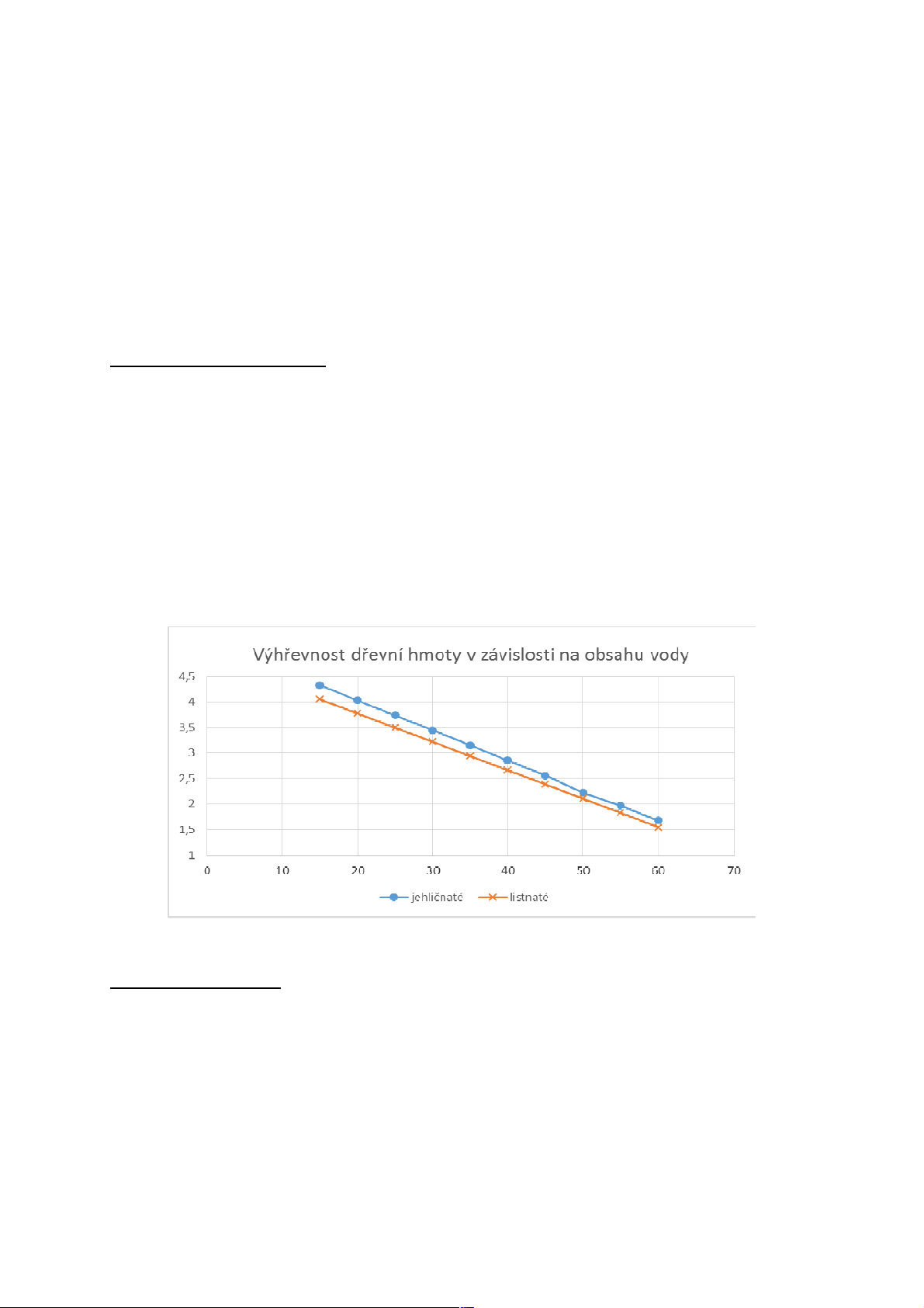
The vertical axis shows the calorific value of wood kWh/kg and the horizontal axis shows
percentually the water content in wood. Moreover the comparison between coniferous and
deciduous trees.
Pic. No. 3 Calorific value of wood material in dependence on the water content
Automatic operation:
Warranty fuel parameters – fuel with which the tests are carried out in TSU:
• Water volume
• Volatile matter volume
• Temperature of ash deformation caused by melting
• Low caking
9
Page 10
-
1
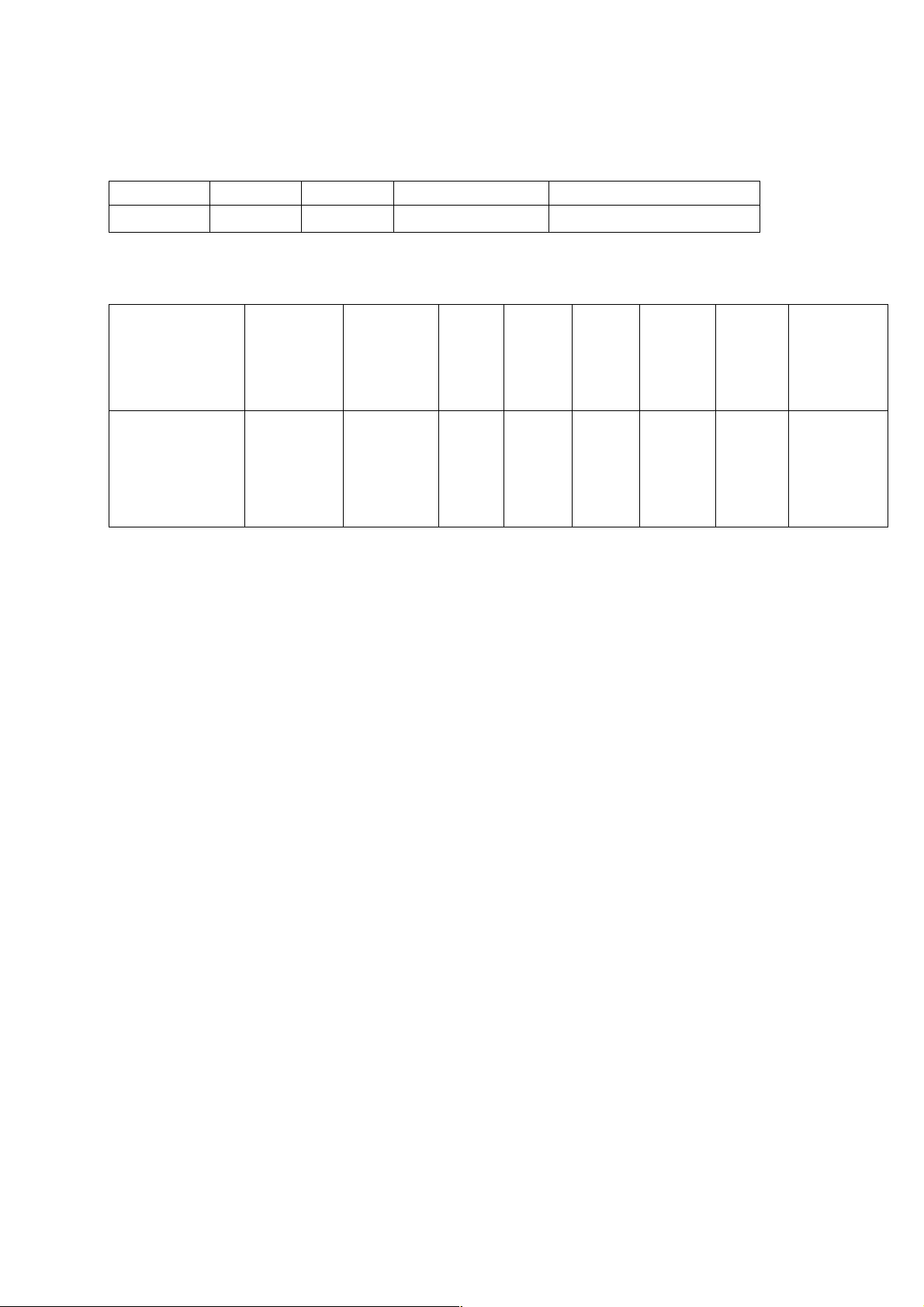
Chart. No. 2 Záruční palivo v automatickém provozu
Fuel Fuel Type Operation Granularity [mm] Calorific Value [MJ.kg
Brown coal
Nut 2 Automatic
10.25 18,2
]
Chart. No.4 Warranty fuel – brown coal (automatic operation)
Tar
content
in dry
matter
[%]
Fuel
Granularity
[mm]
Calorific
Value
[MJ.kg-1]
Ash
content
[%]
Water
content
[%]
Sulfur
content
[%]
Specific
sulphur
content
[g/MJ]
Graded brown
coal from down
Bílina (coal
10,25 18,2 9,8 Max.20 0,76 0,44 15,1 15,71
elaboration
Ledvice) - nut 2
5) Boiler installation
When handling and storing of the product you must be careful to avoid any breaches of
boiler.
Tar content
in
combustible
[%]
The boiler has to be installed by heating specialists with a valid license for the installation
and maintenance of such equipment. The installation project must be undertaken according to
valid regulations.
Before the installation, check the completeness and integrity of the boiler package, if they
are correct with the data according to the product label.
Before commissioning a boiler, it meets the requirements of CSN. (e.g. chimney revision,
approval of the boiler by chimney office, heating system project, heating test, etc.)
The main condition for boiler installation is the involvement of the mixing valve in the
boiler circuit and wiring of the cooling loop. If there will be no cooling loop connected, it is
necessary to ensure heat dissipation during a blackout which will block the pump and the
mixing valve actuator.
Before the heating season it is necessary to check the water pressure and bleed the heating
system.
The manufacturer is not responsible for demages of the boiler caused by errorneous
installation!
10
Page 11

5.1 Rules and regulations
The solid fuel boiler has to be installed by heating specialists with a valid license for
the installation and maintenance of such equipment. The installation project must be
undertaken according to valid.
The heating system must be filled with water which meets ČSN 07 7401 requirements
and, in particular, its mineral content must not exceed the maximum parameters.
Recommended values
Hardness mmol/l 1
Ca2+ mmol/l 0,3
Total Fe & Mn concetration mg/l (0,3)*
CAUTION!!! The manufacturer does not recommend the use of antifreeze.
a) About the heating system
ČSN 06 0310 Heating systems in buildings - Design and installation
ČSN 06 0830 Heating systems in buildings – Safety equipment
ČSN 07 7401 Water and steam for thermal energy equipment with
working pressure up to 8 MPa.
ČSN EN 303-5 CH boilers – Part 5: CH boilers for solid fuel with manual
or automatic delivery, nominal heat output of up to 300 kW
– Terminology, requirements, testing and marking.
b) About the chimney
ČSN 73 4201 Designing chimneys and flues.
c) Due to fire regulations
ČSN 06 1008 Fire safety for heating equipment.
ČSN 73 0802 Fire safety in building – nonproductive – objects.
ČSN 73 0823 Technical fire properties of materials. Flammability rank of
building materials.
d) To the mains
ČSN 33 0165 Electrical regulations. Marking of wires with colours or
numbers. The implementing regulations.
ČSN 33 1500 Electro-technical regulations. Testing of electrical devices.
ČSN 33 2000-3 Electro-technical regulations. Electrical devices. Part 3:
Declaration of the basic characteristics.
ČSN 33 2000-4-41 Electrical devices: Part 4: Safety Section 41: Protection
against electric shock.
ČSN 33 2000-5-51 Electro-technical regulations. Construction of electrical
devices.
ČSN 33 2130 Electro-technical regulations. Indoor electrical wiring.
ČSN 33 2180 Electro-technical regulations. Connection of electrical
devices and appliances.
11
Page 12

ČSN 34 0350 Electro-technical regulations. Regulations for mobile
connections and cable placement.
ČSN EN 60 079-10 Electro-technical regulations. Regulations for electrical
equipment in potentially explosive areas with flammable
gases and vapours.
ČSN EN 60 079-14 ed.2 Electrical apparatus for explosive gas atmospheres - Part
14: Electrical installations in hazardous areas (other than
mines).
ČSN EN 60 252-1 AC motor capacitors - Part 1: General - Performance,
testing and rating - Safety requirements - Guide for
nstallation and operation.
ČSN EN 60 335-1 ed.2 Electric appliances for household and similar purposes -
Safety - Part 1: General requirements.
ČSN EN 60 335-2-102 Electric appliances for household and similar purposes
Safety - Part 2-102: Specific requirements for appliances
burning gas, oil and solid fuel and containing electrical
connections.
ČSN EN 60 445 ed. 3 Basic and safety principles for man-machine interface,
marking and identification.
ČSN EN 60 446 Basic and safety principles for man-machine systems –
Identification of conductors by colours or numbers.
ČSN EN 61000 – 6 – 3 EMC – Part 6 – 3: Generic standards - Emission - for
residential, commercial and light industry.
ČSN EN 61000 -3 – 2 EMC - Part 3 – 2: Limits – Limits for harmonic current
emissions (equiptment input current up to and including 16).
ČSN EN 61000 – 3 –3 EMC – Part 3 – Bounds – Section 3: Limitation of voltage
luctuations and flicker in low-voltage supply systems for
devices with nominal current <16A.
e) About the DHW heating system
ČSN 06 0320 Heating systems inside buildings – DHW set-up –
Design and planning.
ČSN 06 0830 Heating systems inside buildings – Safety equipment.
ČSN 73 6660 Indoor water systems
5.2 Placement options
The boiler can be installed and operated in a simple environment AA5/AB5 according
to CSN 33 2000-3. The boiler is equipped with a portable power cable and plug. The
boiler must be in compliance with EN 60 335-1 ed. 2 Article 7.12.4, positioned so that
the plug is accessible.
The installation and use of the boiler must comply with all ČSN 06 1008 requirements.
12
Page 13

Location of the boiler in conformance to fire regulations:
1. Positioning on a floor made of non-combustible material:
• The boiler has to be set on a non-combustible insulating mat exceeding the dimensions of
the boiler by 20 mm on all sides.
• If the boiler is located in the basement, it is recommended to placed the boiler on a base at
least 50 mm high. The boiler must be established at horizontally level; any unevenness in
the subsctructure is eliminated using the screws under the fuel hopper.
2. Safe distance from combustible materials:
• When installing and operating the boiler, keep a safety distance of 200 mm from
combustible materials
• For easily flammable materials that burn quickly and by themselves even after removal of
the ignition source (such as paper, cardboard, asphalt and tar paper, wood and fibreboard,
plastics, floor coverings) the safe distance is doubled to 400 mm
• The safety distance must be doubled to 400 mm also when the reaction to fire is not proven
Boiler positioning with regard to the necessary handling space:
• In the front of the boiler must be left minimally 1000 mm space for handling.
• The minimum distance between the rear of the boiler and the wall is 400 mm.
• The minimum distance from the side wall of the boiler is 400 mm.
• Above the boiler minimally 450 mm.
Boiler positioning with respect to the mains:
• The boiler must be positioned so that the plug in the socket (230 V/50 Hz) is always
accessible
Location of fuel:
• For proper combustion, it is necessary to use dry fuel. Manufacturer recommended fuel
stored in cellars or at least sheltered.
• It is impossible to store fuel for the boiler or next to the boiler at a distance of less than
400 mm.
• The manufacturer recommends to keep the distance between the boiler and fuel minimaly
1000 mm or store the fuel in a different room than the installed boiler.
Connecting to the heating system must be made by a heating specialist with a valid
license.
13
Page 14

Pic. No. 4 Location of the boiler
5.3 Connecting the boiler to the chimney and outlet of combustion products
The flue must lead to a chimney flue with a minimal possible lenght. The flue must
rise towards the vent, in no case shall fall. The flue must be mechanically strong, tight passes
and the accessible for cleaning. The inner diameter of the flue shall not be greater than the
diameter of the flue and it is forbidden to narrows the flue toward the chimney. The use of
large quantities of knees is not recommended.
Methods of implementation flues are given in ČSN 06 1008.
The chimney must be designed so that the chimney flue develop a sufficient draft
(referred to the technical parameters of the boiler) and led the flue gases into the atmosphere.
The manufacturer recommends the chimney inset.
If the chimney draft is big or small it is necessary to install the draft regulator.
5.4 Air supply to the boiler
In the room where the boiler is installed, it must be ensured continuous supply of air
for combustion and ventilation. If it is not provided, it is necessary to ensure air vent from the
outside according to the standards.
5.5 Connecting the boiler to the heating system
The boiler is connected to heating system with 2" mouthpiece. For the filling and
draining of the boiler there is located an inlet (drain) valve beneath the return water. Filling
and draining should be performed using a hose. The heating system must be filled with water
that meets the requirements of ČSN 07 7401.
The boiler must be connected to the circuit so the temperature of the return water was
above 55°C. This can be achieved by mechanical or controlled mixing valve, which is
14
Page 15

controlled by the control unit. If the minimum temperature of the return water is not reached,
manufacturer can not guarantee the required service life of the boiler.
Boiler construction allows the connection of the boiler with a maximum pressure
according to the technical parameters of the boiler.
Connection the cooling loop as it is described in chapter 5.6
5.6 The cooling loop connection
Connection of the cooling loop (unless otherwise stated) is performed according to
pic. n.5. First 1/2" outlet serves for the water main connection and the other one 1/2" outlet
serves for joining runoff into drains.
In case the boiler is overheated (temperature above 95°C) the thermostatic valve will
automatically open. This valve is installed on cold water supply pipe. When the overheating
alarm turns on, the fan will stop and boiler remains in stable heat mode. Bimetallic sensor
which senses temperature is placed in the boiler sump. After the end of the cooling proces, is
the boiler temperature lower by 15°C then water flow will stop automatically.
This protection system only works reliably provided a constant supply of pressurized
water from the water main. Due to a mechanical protection which serves mainly for situations
as a power failure. It is necessary to be careful while connecting it to a water system!
Connect the cooling loop is the only condition for safe operation of the boiler.
Connections must be performed only by authorized personnel.
Pic. No. 5 Cooling loop
15
Page 16

5.7 Connection to the mains
The power supply 230 V / 50 Hz with boiler attached by a cord and plug. The plugging
must comply with CSN. The plug must always be in reach. Unauthorized intervention in the
electrical installation of the boiler will cause damage and can also cause fatal injuries.
5.8 Boiler parts installation
Situated the boiler on the substructure (pad) into a horizontal position.
5.8.1 Installation of the boiler casing and thermostatic valve
The boiler is always supplied with the casing and it is also neccesary to install the
bimetalic thermostatic valve on the left side of boiler:
1. Remove the upper casing – upward movement.
2. Remove the back casing.
3. Remove the screws on the top of the casing and remove the side casing.
4. Screw the bimetalic element to mouthpiece on the left side of boiler., Pic. No. 5
5. Unhinge the side casing.
6. Install the side, upper and back casing to its original state.
ATTENTION: If you do not install the supplied thermostatic valve, the boiler during
pressurization squirt water.
5.8.2 Exhaust fan connection
Apply sealant to outlet of the flue pipe and place the exhaust fan. The flue pipe outlet
must be placed upwards! After settling, tighten the screws on the exhaust fan and use sealant
thoroughly to avoid air intake.
Connect capacitor according to wiring diagram capacitor.
NCT4C, NCJ4C
Pic. No. 6 – Wiring diagram of the capacitor
16
Page 17

5.8.3 Universal burner installation
1. Remove the cast iron collar from the burner body
2. Seal the flange burner head
3. Put the universal burner into the base without the collar and tighten the bolts.
4. Use stove sealant on the collar and puti t back (Pic. No. 8)
5. Connect the burner feeder and shorten the leg as required. It must correspond to the red
mark
Pic. No. 8 Sealing the top cast-iron collar and flange
5.8.4 Fan and screw feeder installation:
1. Put the fan in place and bolt it on.
2. Connect the screw feeder and make sure it correspond to red mark.
Pic. No. 9 Fand and feeder installation
5.8.5 Tank installation:
1. When assembling the fuel feeder to the base and to the fuel hopper, first, ensure that
everything is in horizontal level and then tighten the bolts.
2. Apply sealant to the fuel screw feeder where is the contact with the surfuces of the fuel
hopper. Put he fuel hopper in place and tighten the screws.
3. Follow the instructions of the burner manual, which is part of the package.
17
Page 18

Pic. No. 10 Installing the hopper on screw feeder.
5.8.6 Control unit FOX installation:
1. Place the control unit from the left or right side of the boiler.
2. Connect the temperature sensors according to manual.
• Put the CH sensor into the reservoirs in the boiler’s water output connection.
• The DHW sensor is placed into the boiler reservoir or taped directly onto he pipe
(the sensor is set to OFF in the factory settings, the sensor is only used when the
boiler is in use).
• The temperature regulation sensor (an emergency thermostat) i sput into a separate
reservoir in the boiler’s water output pipe, as close to the boiler as possible.
• The hopper temperature sensor is put into a pipe placed on the screw feeder, behind
the fan.
• The rest of the sensors is possible to connect according the FOX manual.
3. Connect the control unit, feeder, fan, pump according to the manual.
4. Continue to follow the instructions on the control unit FOX manual.
6 Boiler operation by user
The boiler must be operated according to the manufacturer's instructions to avoid any
problem caused by the user, so it is highly recommended to read instructions manual for the
boiler and control unit FOX.
This appliance can not be used by younger children than 8 years old and persons with
reduced physical, sensory or mental disorders or by users without sufficient experience. They
are able to operate the boiler only if they are under the supervision or receiving the
instructions from the specialist and they understand the dangers that they come into contact.
Children should not play with the appliance. Cleaning and maintenance of the boiler can not
be perform by the kids.
Once in every 14 days period is needed to check the water pressure in the heating system.
If the pressure is low it is necessary to replenish the water. If the boiler in the winter period is
not operated, it is recommended to drain the water from the system due to freezing. The
18
Page 19

discharged of the water is not recommended only when it is necessary and for the shortest
period of time. At the end of the heating season, it is necessary to thoroughly clean the boiler
and check the boiler for any damages that might be caused by the operation.
It is recommended to clean the impeller and an air chamber of the exhaust fan twice in a
year.
Při ručním režimu musí být nad hořákem umístěny šamotové desky. Při automatickém
režimu se desky musí vytáhnout.
6.8 Verification activities before usage of the boiler
Before the commissioning of the boiler it must be checked:
a) naplnění otopného systému vodou
The mineral content (hardness) of the water used inthe boiler must comply with ČSN
07 7401 standards and it is essential that, if the mineral content is not in compliance, the water
must be softened – this is covered in Section 05.01.
Heating systems with open expansion tanks allow direct contact between the water and air in
the environment. During the heating season the expanding water in the tank absorbs oxygen,
which hastens the effects of corrosion while allowing significant water evaporation. If more
water is added, it must be treated according to ČSN 07 7401 standards.
The heating system must be thoroughly rinsed out in order to eliminate all impurities.
During the heating period a constant volume of water in the heating system must be
maintained. When adding water to heating system, It must be ensured that no air is drawn into
the system. Water from the boiler and heating system must never be discharged or removed
except in cases of emergency such as repairs etc. Draining the water and replenishing it
increases the risk of corrosion and scaling. If it becomes necessary to add water to the
heating system, do soonly when the boiler is cold to avoid cracking.
b) A tight heating system
c) Connecting the flue – The flue must be approved by a chimney inspector
d) Connection to the mains
You must connect the flexible cord with a plug into a standard socket 230 V/50
Hz/10A.
6.9 Firing
Please note that making fire is strictly forbidden to use flammable substances.
− Check the settings in the boiler control, operating control FOX.
− Check the amount of water in the heating system by looking at the gauge.
− Open the shut-off valves between the boiler and the heating system.
− Check the operation of pumps (mechanical spinning)
− Clean the boiler (if it is not the first firing). The ash door must be permanently closed
during the fire making and operation.
19
Page 20

− During the manual mode there has to be vermikulit plates above the burner. Automatic
mode is working without these plates.
Manual mode - gasification:
− Check the vermikult plates above the burner.
− Primary air slider control set to the open position.
− At the bottom of the filling chamber make fire using the small chips, sawdust or shavings.
− Put a few pieces of small wood in to the filling chamber, close the filling door.
− Ignite the wood throught the middle door.
− Start the control unit, using the fan we will support combustion in the chamber, which
create a hot layer in order to fill up the filling chamber with the wood.
− If we follow the correct procedure we should be able to stoke a wood to the chamber in
about 10 – 15 minutes.
− Stable combustion indicates that we can set the boiler to the desired performance and
reduce the amount of primary and secondary air.
Automatic mode:
− Pull out the plates above the burner.
− Clean the burner and ash pan (not for the first firing). The ash door must be shut at all
times when the boiler being fired up adn when i tis in operation.
− Fill the fuel hopper with the appropriate amount of fuel. After filling the fuel hopper, close
it tightly to prevent possible air intake into the burner through the feeder.
− Switch the unit on in manual mode and start feeding the feeder using the “+ button”. The
fuel must be fed into the burner to approximately 1 cm below the edge. The feeder will
feed the burner for approximately 7 minutes. If the motor gets too hot, the thermo-fuse will
cause the feeder to stop. After cooling, the motor begins feeding again.
− The fuel should be ignited with liquid or solid fire starters, or with wood chips.
− Ignite and let it burn.
− Allow to burn for about 3 minutes, then gradually start the fan by pressing the “-button” In
the beginning, start the fan and then stop it. If the fan blows too hard in manual feeding
mode, the maximum fan speed needs to be set in the service menu.
− When firing up, keep the fuel level about 2 cm below the edge of the cast iron grate.
− When the space inside burner has completely heated up, the boiler can be switched to
automatic mode by pressing the ↑ button.
Checking the shape of the flame at automatic operation
The shape of the flame gives us information about the correct settings for the nominal
rating. It is reccomended to check the shape of the flame everytime you change the fuel.
When checking the shape of the flame, make sure that the boiler is set at nominal power.
Brown coal nut 2:
20
Page 21

Pic. No. 13 Optimal flame shape Pic. No. 14 Poor flame shape
6.10 Stoking
Manual operation - gasification:
Hopper lasts for about 8 to 12 hours operation at medium power. In energy saving
mode, the boiler should last up to 24 hours.
a) Slightly ajar the top door, in order to exhaust the woodgas from the filling chamber.
b) Completly open the upper stoking door.
c) Make sure that the basic layer is burning.
d) Fill up the filling chamber with the fuel.
e) Closed the upper stoking door.
Automatic operation:
The hopper content for the brown coal nut 2 last for 3 days in nominal power 25kW.
a) Turn control unit FOX off.
b) Wait 5 minutes.
c) Open the the hopper lid.
d) Fill the hopper.
e) Close the hopper lid.
f) Turn on the control unit FOX.
g) Set the hopper capacity to 100%.
6.11 Combustion control
Manual operation - gasification:
During the operation of the boiler it is necessary,to ensure the burning was carried out
as perfectly as possible for efficiency reasons and to minimize the harmful substances such as
hydrocarbons and tar which could clogged the boiler and flue. Combustion quality determines
the types and moisture of the material, according to Pic. no. 3. Further combustion affects the
way of stoking the filling chamber and self regulation of the boiler.
In warmer seasons it is imperative to firing and stoking to the boiler, so boiler will
work in rated power without an outage at least 2 hours. Therefore the dose of fuel in the
warmer spring and autumn days should be smaller. See chapter 6.3.
Combustion can also be affected by the amount of primary and secondary air. It could
be regulated by the rod on the left side of the boiler. The burning of harder wood, briquettes
and small materials need a higher levels of secondary air.
Recommended settings of primary and secondary air can be seen on pic. 6
21
Page 22

Pic. No. 6 – Regulation of primary and secondary air
PREDATOR
PREDATOR
PREDATOR
PREDATOR
PREDATOR
PREDATOR
PREDATOR
PREDATOR
PREDATOR
Z - closed, O - Open
Automatic operation:
During the operation of the boiler it is necessary,to ensure the burning was carried out
as perfectly as possible for efficiency reasons and to minimize harmful substances which
could eventually clog the boiler, flue outlet and stop these substances from leaking into the
atmosphere. Combustion quality determines the particular kind of material and humidity. It
should always be used according to the manufacturer's warranty fuel.
In automatic mode, it is necessary to close primary and secondary air. Furthermore, the
ventilator flap must be closed to prevent the suction of air. It is also required to pull out
the vermikulit plate placed above the burner.
6.12 Power settings and regulation
Power control is governed by the exhaust fan speed. In automatic mode, the
performance depends on the amount of fuel delivered to the burner and fan speed. Then
begins the venturing excess heat energy to the heating circuit. If the heating circuit is heating
up, so the control unit switches off the fan and boiler passes into the so-called attenuation
mode. If the water temperature drops, the boiler will go back into operation.
The boiler can be connected to a room thermostat which is superior to whole heating
system and boiler goes into decline based on achieving the desired temperature in the room.
When is the temperature in the room lower, the boiler starts heating again.
Chart. 7 Control unit parameters - wood
Boiler type
Exhaust fan speed 41 55 70 85
Primary air 6 7 8 9 10
Secondary air 3 3-4 4 4-5 6
Chart. 7 Control unit parameters at nominal power – brown coal
Boiler type
Feeding time 5 5 6
Feeding idle time 12 10 10
Fan speed 36 37 39
Exhaust fan speed 37 48 59
20
20
25
25
30
30
35
35
6
8
40
70
40
100
22
Page 23

Chart. 8 Control unit parameters at minimal power – brown coal
PREDATOR
PREDATOR
PREDATOR
PREDATOR
Boiler type
Feeding time 2 5 6 6
Feeding idle time 20 40 30 37
Fan speed 29 31 33 34
Exhaust fan speed 34 36 38 40
20
25
30
35
6.13 Ash removal
Manual operation - gasification:
The ash is collected in the middle door. When is the coating thickness of the ash is
about 5-7 cm. We take the ash throught the middle door or we can use the nozzle for
collecting the ash in the post combustion area, where it is possible to take off the ash throw
ignition door.
Automatic operation:
The ash is collected throw bottom ash door. Ashes are encouraged to remove every 24
hours of operation.
6.14 Boiler cleaning
Main boiler cleaning is performed by using the lever on the left (right) side of the
boiler. Cleaning is done by using the turbulators which are located in the main heat
exchanger.
Manufacturer is recommending to clean the heat exchanger walls atleast once a month.
6.15 Maintenance and inspection of the boiler
During the operation of the boiler it is necessary to pay attention if there are any
leaking tar or contamination to the air vents. Air valves must open and close smoothly.
Primary and secondary air flap is an important element of the boiler and must be
checked frequently and even the air ducts must be kept clean. If something prevented
complete opening or closing the valve, it should be cleaned immediately. This may lead to the
achievement of the desired output of the boiler.
Never take the ceramic bricks outside of the boiler and check them visually after the
cleaning. There must be no clogging. The bricks might be demaged during the operation due
to temperature cycles. The changing of the brick is recommended after the worse operation of
the boiler overall.
In automatic mode, it is imperative to keep hopper always full. If remains small amount of
the fuel in the hopper it is necessary to refill it. When adding fuel or checking the fuel level be
sure to cover the hopper tightly. Follow the instrucion according to chapter 6.3!
The air intake mixer should be cleaned every 3 months. The mixer has an influence on the
correct airflow.
If a hard object gets stuck in the feeder screw causing the shear fuse to go, replace the
fuse. Clean the unwated materiál from the screw through the hopper cleaning opening and use
23
Page 24

a 19 mm wrench to rotate the screw. Then install a new fuse and put the burner back into
operation.
WARNING: Before performing this operation, make sure the boiler is disconnected
from the power supply (the plug is removed from the socker) and fuel is cooled to avoid
a back-burn.
In the event. Of a power failure, the wax cap acts as a safeguard against back-burn and
extinguishes burning fuel. Always keep the tank filled with water.
1x Clean the inside of the combustion chamber, the smoke outlets and fittings once a
month. Do not clean the boiler inless i tis cooler than 40°C. Use the cleaning hatch in the
bottom to remove the ash from the flue fitting. Ensure tgat it is airtight after cleaning.
Check sealing cords on the door, if necessary replace the sealing wires.
It is recommended to periodically perform a visual inspection of the boiler.
7 Contol unit FOX
Pic. No. 7 Control unit FOX
7.8 Control unit FOX description
Boiler regulator FOX, is modern electronic device intended to control automatic
operating and manual gasification process. This regulator is multifanctional device:
- It automatically maintains desired temperature of the boiler by controlling the
combustion process,
- Controlling the exhaust fan speed,
- Controlling the feeding cycles during the automatic operation
- Controlling the fan speed
- Automatically maintains the set temperature of HUW,
- Automatically maintains preset temperature of several independent mixer heating
cycles.
The preset temperature of heating cycles and boiler can be set on the basis of a
weather sensor readouts. Possibility of cooperation with room thermostats, separate for each
heating cycles facilitates maintaining comfortable temperature in the heated rooms. Moreover,
if need arises, the device enables a reserve boiler (gas or oil-fired). Regulator can cooperate
24
Page 25

with an additional control panel situated in living quarters. The device is operated in an easy
and intuitive way.
7.9 Operation of the controller
The simular manual for operating of control unit is incluaded in package. To avoid any
problems, we advise you to read carefully the installation manual, before you start using it.
7.10 Temperature sensors installation
CH temperature sensor
This sensor detects the current water temperature in the boiler. This temperature is
shown on the red LCD control panel. Operating modes are set according to this value. The
sensor is connected to the boiler output to have the best possible contact and heat transfer. It is
either installed in a reservoir or it is taped to pipe. The brass part should have the best contact.
The wire must never come into direct contact with any element of heating system!
To ensure the accurate measurement of temperature, it is recommended to use thermal
grease.Oil must not be used as it can damage the sensor!
DHW temperature sensor
This sensor reads water temperature in the DHW tank. DHW pump start-ups and shut-
offs are initiated according to this sensor’s readings. It is either installed in a reservoir or it is
taped toa pipe. This sensor is set to OFF in the factory settings so, it must be set in the main
menu for use.
Emergency thermostat - bimetallic sensor
The independent thermocouple sensor protects the system against overheating. It
operates independently of the control unit and, when it detects temperatures above 90°C, it
will immediately shut the fan and the feeder down to prevent the burner from heating up any
further. The alarm will switch the control unit to OFF mode!After checking the system, the
user can press to switch the system to HEAT mode.
The first sensor is installed on the boiler’s hot water output. It is placed in the reservoir
or taped onto the tube with insulation. For the best results, remember that the wire must not be
in direct contact with the tubes!
The sensor is installed with the CH sensor!
Pic. No. 8 – Thermal sensor installation
CAUTION:
The sensors must not be immersed in liquids such including water, oil, etc.
During assembly and operation, the sensor cables must not come into contact with hot
pipes or other elements of the heating system.
25
Page 26

7.11 Technical data
W
S.n. Specification Unit Units
Power supply V 230V/50Hz +/-10%
1
2
3
4
5
6
7
8
9
10
attage
Operating temperature °C 5÷50
Output load for CH, HUW pump and floor,
circulation; valves
Output fan load A 0,6
Output screw feeder load A 2
Temperature range °C 0÷90
Temperature measurement accuracy °C 1
Adjustable temperature range °C 45÷80
Range of temperature sensor °C -25÷90
W 11
A 0,5
7.12 A wiring diagram
7.13 Commissioning
Control unit FOX can be put into the operation only by a specialist with a valid license.
The regulator should be put into operation according a manufacturer instructions.
26
Page 27

8 Important alerts
• The boiler must only be used for the purposes of the use to which it is intended.
• The boiler can only be operated by adults who are familiar with the operating
instructions. Leaving the children unattended near by a boiler in operation is prohibited.
• Children should be supervised to ensure that they do not play with the appliance.
• If there is a potencional risk of penetration of flammable vapors or gases into the boiler
room or at work, during which a temporary fire or explosion (bonding floor coverings,
painting with flammable paints, etc.), the boiler must be switched off before the works.
• The firing the boiler PREDATOR is FORBIDDEN to use flammable liquids (gasoline,
alcohol, etc.).
• During the operation of boiler PREDATOR is FORBIDDEN any way to overheat it.
• The boiler and closer than the safe distance allowed is not possible to store any
flammable objects.
• When you are removing the ash from the boiler there must be a minimum distance of
1500 mm from the boiler for storing flammable substances. The ashes must be disposed
of non-combustible container with a lid. Wear protective equipment.
• After the heating season is necessary to clean the boiler and flue. Boiler room must be
kept clean and dry.
• It is forbidden to interfere with the construction and installation of electric boilers.
• The system must be equipped with a relief valve with a maximum pressure of 2.5 bar,
its dimensions must correspond to the rated boiler output. In case of any questions,
please contact the contract assembly companies and service organizations.
• Poor fuel quality can significantly affect the performance and emission characteristics
of the boiler.
• During assembly, installation and operation of the appliance it is necessary to comply
with the standards which apply in the specific country. If these conditions are not
fulfilled it is not possible to claim any warranty repairs.
•
According to Government Regulation 91/2010 Coll. - The conditions of fire safety
during the operation of chimneys, flues and fuel appliances, operator is obliged to carry
out regular cleaning and inspection of flueways.
9 Disposal of the product after its service life
Packing should be disposed of as follow:
• plastic wrappings, cardboard packaging can be discarded at a waste facility
• metal strapping can be discarded at a waste facility
• the wooden base is intended for a single use must be discarded. The disposal of the base
is subject to Act 94/2004 Coll. and 185/2001 Coll. as amended.
Because the boiler is manufactured from common metals, dispose of the individual parts
as follows:
• mixer (gray cast iron) can be discarded at a waste facility
• piping, shell can be discarded at a waste facility.
• other metal parts can be discarded at a waste facility
27
Page 28

10 Warranty and liability for defects
The company provides the following guarantee:
The boiler warranty is 24 months from the date of issuing an invoice.
For possible complaint of supply, the customer must submit the boiler casing
packaging label. It is located on the carton in which the casing is shipped.
The user must have a professional assembly service company put the boiler into
operation and service the equipment, otherwise proper functioning can not be guaranteed. A
completed „certification of quality and completeness of the PREDATOR boiler“ document
can be used as a „Certificate of warranty“. The user is obliged to have the boiler undergo
regular maintance.
Defects should be reported immediately after detection in writing and by telephone.
Failure to follow these instructions will void the manufacturer’s warranty.
The manufacturer reserves the right to make changes related to product innovations
that may not be included in this manual.
11 The warranty does not cover
- defects caused by improper assembly, improper handling or defects caused by
improper maintenance (more in Section 8)
- product damaged during transport or other mechanical damage
- defects caused by improper storage
- defects caused by failure to observe water quality guidelines for the heating system
(more in Section 5.1 and 7.2) or through the use of anti-freeze
- defects caused by not following the instructions provided in this manual
- failures caused by operating the boiler on non-warrantied fuel (see Tab. 3 and
11 Troubleshooting
Issue Possible cause Resulotion
Control unit cannot be
turned on
Boiler does not reach the
required parameters
- no voltage in the network - check the power network
- plug incorrectly inserted in the wall
socket
- defective control unit - replace the unit
- frayed power cords - replace the cord
- LED indicators do not light up - replace demaged fuse
- low water level in the heating system - refill
- pump output too high - adjust the flow rate and pump
- power output too low for the system - poorly prepared project
- check the socket connection
switching
28
Page 29

Door leaks smoke
replaced by an authorized service
!
Fan wobbles or is noisy
Smoke in the boiler
room
The boiler is
overheating and hardly
regulatable
- wood moisture above 15%, wrong
dimensional of wood
- clogged nozzle
- demaged nozzle
- insufficient draft - new chimney, or correct improper
- excess flue draft - install a damper in the flue
- inadequately cleaned boiler - clean the combustion chamber , the
- closed primary air flap. - clean and free the flap
- closed secondary air flap - clean and free the flap
- improperly adjusted door hinges - tighten the hinge screws
- faulty sealing cord - replace the cord
- overheated boiler – temperature
limiter activation (an emergency
thermostat)
- inoperable motor - replace the motor
- demaged to the power cord - replace the cord
- fan is switched off due to safety
system. The boiler is overheated –
temperature higher than 95°C.
- leaky door - replace the cord
- the water in the boiler is not
circulating or in the heating system
- safety thermostat demaged – the
boiler (fan) is operating even in higher
temperature than 95°
- closed, barely opened mixing valve.
- overlarge boiler output
- use the fuel with maximum moisture
up to 15%, dimensions which
corresponding to manufacturer
requirements
- clean and remove objects which
stucked in a crevice nozzle or in the
suction holes.
- replace of nozzle.
- manufacturer highly recommends to
use an authorized service!
connection
nozzle, post-combustion area, ashtrail
and main heatexchanger
- wait until temperature drops to
approximately 70°C, then press the
temperature limiter placed on control
unit
It is neccesary to cool the system.
Afterwards, the fan will turn on
automaticaly.
-
tighten the screws
- check water level in the heating
system, pump status and its
functionality
- clean the pump filter
-
- check the functionality of mixing
valve
- make an adjustment of the heating
system
- recommended to use the storage tanks
29
Page 30

12 Recommended boiler connection
The manufacturer recommends the connecting the boiler with a storage tank. Size of the
storage tank selected according to the required boiler output which means 55 liters per 1 kW.
If it is a 20kW boiler it should be used a tank size of at least 20 kW x 55 liters = 1,100 liter
storage tank.
Diagram with the storage tank – without an additional moduls: 1 - boiler, 2 – control unit
FOX, 3 – fan, 4 – boiler temperature sensor, 5 – flue temperature sensor, 6 – boiler pump, 7 –
storage tank, 8 – HUW pump, 9 – HUW tank, 10 – HUW circuit pump, 11 – HUW sensor, 12
– mixer servo, 13 – mixer temperature sensor, 14 – mixer pump, 15 – thermostat, 16 –
thermostatic, mixing valve for protecting the return water, or Ladomatt, 17 – upper sensor for
storage tank, 18 – temperature (weather) sensor
30
Page 31

EC DECLARATION OF CONFORMITY
We:
Lhota u Vsetína 4
755 01 Vsetín
IČ: 29220327, DIČ: CZ29220327
in accordance with the following Directive(s):
2006/35/EC The Machinery Directive
2006/95/EC The Low Voltage Directive
2004/108/EC The Electromagnetic Compatibility Directive
hereby declare that:
Equipment: Combi boiler
Model: PREDATOR 20 – 40 kW
Serial number: 2030xxxx, 2530xxxx, 3030xxxx, 3530xxxx, 4030xxxx
where appropriate, are in conformity with the following harmonized standards:
ČSN EN ISO 12100:2011 (EN ISO 12100:2010)
ČSN EN 303-5:2013 (EN 303-5:2012)
ČSN EN 60335-1 ed. 3:2012 (EN 60335-1:2012)
ČSN EN 60335-2-102:2007/A1:2010 (EN 60335-2-102:2006/A1:2010)
ČSN EN 55014-1 ed. 3:2007/A1:2010/A2:2012 (EN 55014-1:2006/A1:209/A2:2011)
ČSN EN 55014-2:1998/A1:202/A2:2009/Z1:2008 (EN 550142:1997/A1:2001/IS1:2007/A2:2008)
I hereby declare that the equipment named above has been designed to comply with the
relevant sections of the above referenced specifications. The unit complies with all appliable
Essentials Requirements of the European Union Directives. The declaration will loses its
validity if changes will be made without approve of manufacturer.
documents issued by the certification institute:
Certificate of declaration No. 141299021 on 31.07.2014, issued by the Technical test institute
Piešťany, š.p. Krajinská cesta 2929/9, 921 01 Piešťany, IČO: 00 057 380
The product is safe under conditions of usual usage.
During the conformity assessment procedure under § 12, para. 7 of the Act No. 264/1999
Coll., As amended.
On 31 July 2014 in Vsetín
KOVARSON s.r.o.
Executive director of KOVARSON s.r.o.
31
Page 32

KOVARSON s.r.o.
Lhota u Vsetína 4
755 01, Vsetín
tel. ČR: +420 571 420 926
tel. SR: +421 949 176 717
email: info@kovarson.cz
32
 Loading...