

Kostrzewa PFL 15, PFL 25, pellets fuzzy logic 2, PFL 50, PFL 40 Service Manual
...

Pellets Fuzzy Logic - Service Manual- ENGV 10.11
Experts in biomass heating
Dear Users of Pellets Fuzzy Logic Boiler.
Before you connect and start up the Pellets Fuzzy Logic boiler check
the parameters of the chimney according to the data contained in the
enclosed table (chimney draft, chimney cross-section), and the device
matching with the heated surface (heat demand of the building).
Basic principles for the safe operation of the boiler!!!
1. Read the service manual before starting up the boiler.
2. Before starting up the boiler check that the connection
to the central heating system and the flue is in accordance
with manufacturer’s recommendations.
3. Do not open the doors during the boiler operation.
4. The tank cover must always be tightly closed
during the boiler operation.
5. Do not allow the fuel tank to be emptied completely.
For your safety and comfortable use of the boiler, please return
the PROPERLY COMPLETED (CONTAINING ALL ENTRIES AND
SEALS) last copy of the warranty card and the boiler quality
and completeness certificate (the last page of this service
and installation manual ) to the following address:
SERWIS KOSTRZEWA
ul. Przemysłowa 1, 11-500 Giżycko, POLAND
woj. warmińsko – mazurskie
tel. +48 87 428 53 51 lub +48 87 428 11 34
e-mail: serwis@kostrzewa.com.pl
Sending back the warranty card will allow us to register you
in our database of Pellet Fuzzy Logic users and provide fast
and reliable service.
IMPORTANT !!!
PLEASE NOTE THAT FAILING TO RETURN THE WARRANTY CARD
OR RETURNING THE WARRANTY CARD AND BOILER QUALITY AND
COMPLETENESS CERTIFICATE INCORRECTLY FILLED WITHIN TWO
WEEKS FROM THE DATE OF THE BOILER INSTALLATION, HOWEVER
NOT LONGER THAN TWO MONTHS FROM THE PURCHASE DATE,
RESULTS IN THE LOSS OF WARRANTY FOR THE HEAT EXCHANGER
AND ALL COMPONENTS OF THE BOILER. THE LOSS OF WARRANTY
WILL CAUSE THE DELAY IN PERFORMING REPAIRS AND NECESSITY
TO COVER THE COSTS OF ALL BOILER REPAIRS WITH TRAVEL
COSTS OF THE SERVICE PERSONNEL INCLUSIVE.
Thank you for your understanding.
Yours sincerely,
Dear user of
KOSTRZEWA
equipment!
We want to take this opportunity to thank you for
choosing our equipment. You have selected
the highest quality product of the company
known and appreciated throughout the country.
The Kostrzewa company was established in
1978.Since the beginning of activity they
are dealing with the production of fossil fuel
and biomass-fired boilers for central heating
applications. Within theirs 30 years’ activity
the company improves and upgrades their
equipment so as to be a leader among the Polish
manufacturers of solid fuel-fired boilers.
The implementation and designing department
for new technologies was created in the
company to continually improve the equipment
and implement the new technologies.
We want to contact with each customer by
an intermediary of the companies, which will
professionally represent our company.
Your opinion on the activities of our company
and our partners is very important to us. Striving
to continuously improve the level of our products,
we ask you to make any comments about our
products and service rendered by our Partners.
Have the warm and comfortable days
through the whole year!
KOSTRZEWA sp.j.
ENGV 10.11
2

Pellets Fuzzy Logic - Service Manual- ENGV 10.11
Experts in biomass heating
Index
I. Pellets Fuzzy Logic Boiler manual
1. General 4
2. Technical data of Pellets Fuzzy Logic boiler 5
3. Fuel parameters 6
4. Description of Pellets Fuzzy Logic boiler design 7
5. Pellets Fuzzy Logic boiler accessories 8
6. Pellets Fuzzy Logic protecting and control fittings 9
7. Pellets Fuzzy Logic Boiler location and installation 10
8. Boiler commissioning - Instructions for AS (Authorized Service) 12
9. Boiler control system user manual 13
10. While using the boiler, keep in mind ... 13
11. Starting up the boiler - User Instructions 14
12. Cleaning and maintenance 21
13. Troubleshooting 25
14. Instructions for boiler disposal after expiration of its service life 26
II. PELLETS CONTROL M Fuzzy Logic Boiler controller service manual
15. General 30
16. Electrical wiring system 32
17. Operation 35
18. Technical data of Pellets Control M Fuzzy Logic 44
19. Terms and Conditions of Warranty and Defects Liability. 46
3

Pellets Fuzzy Logic - Service Manual- ENGV 10.11
Experts in biomass heating
1.1 Application and advantages
of the boiler
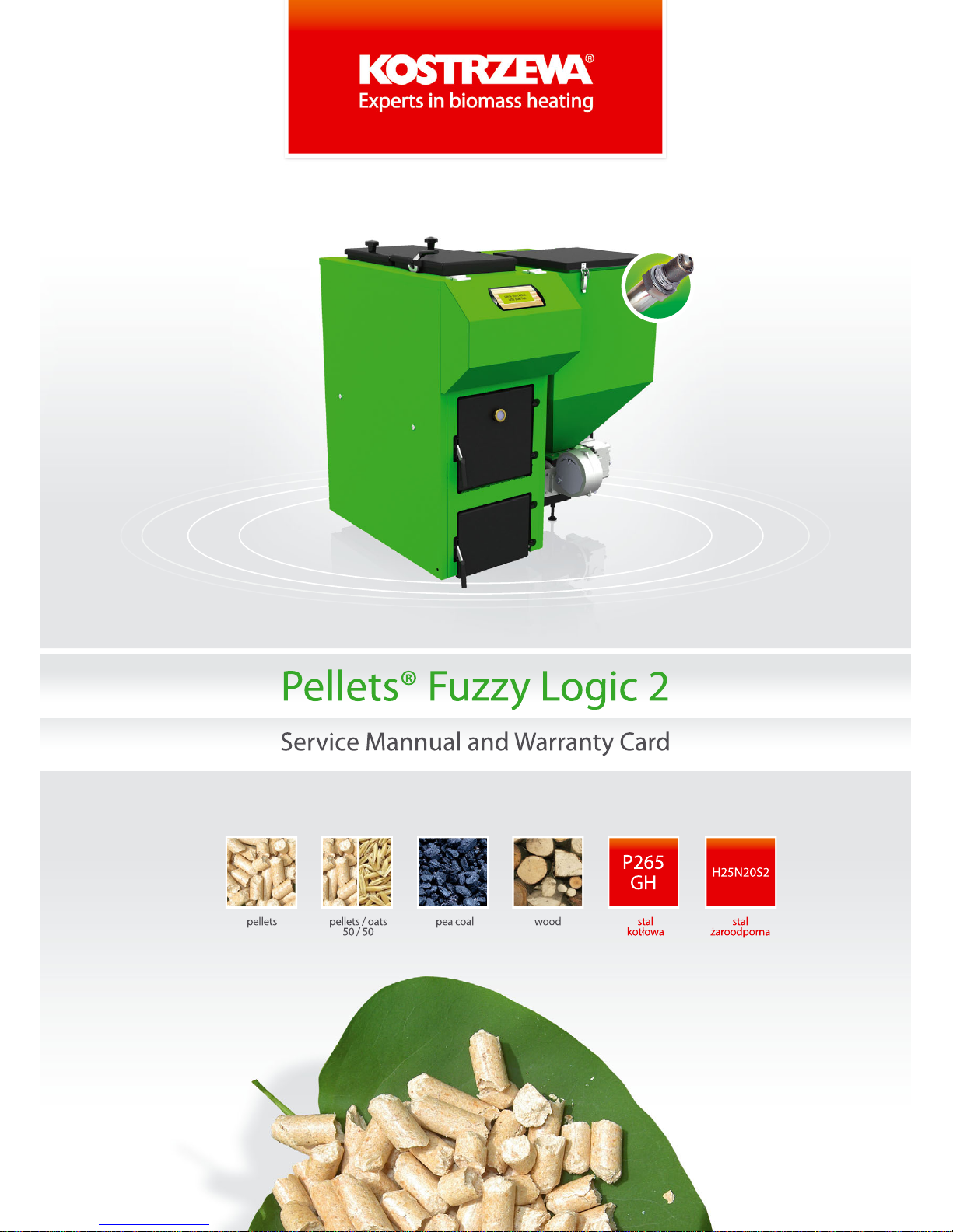
Automatic PELLETS FUZZY LOGIC boiler is intended for
combustion of solid fuels such like pellets, pea coal, cereals, wood.
It can be used to heat single or multi-family houses, smaller resorts,
workshops, schools, offices, etc.
1.2 Advantages of Pellets Fuzzy Logic
boiler
Modern design of steel heat exchanger, allowing the achievement of efficiency above 90%;
Possible combustion of four types of fuels;
Automatic fuel ignition - pellets;
Automatic fuel ignition – pea coal;
Automatic fuel ignition – cereals;
Automatic operation of the boiler controlled by weather controller and room thermostat;
To improve the quality of combustion Pellets Fuzzy Logic is
fitted with three fans (two pressure and one exhaust);
- exhaust fan - to eliminate odors and dust in the boiler room;
during the combustion of fuels the fan draws flue gas from the
boiler to the chimney. Fan rotor, through which flue gas pass,
is made of stainless steel;
Door viewer - to not open the door during operation,
a sight glass was mounted to view the flame;
Flue gas temperature measurement - this feature allows you to
control the efficiency of the boiler and its settings. It informs you
also about the point at which the boiler heat exchanger must be
cleaned;
Two operation modes;
- Summer - during the summer season domestic hot water
is heated;
- weather - along with the external temperature sensor and the
room temperature controller (standard boiler equipment);
Modulation of the burner operation by Fuzzy Logic method
- no feeding and standstill times - automatic power adjustment
to the heat demand of the building - from 10% to 100% of the
boiler output;
Lambda probe - infinitely adjustable fan speed (air is tuned
by the lambda probe and not by the user. Just press the start
button and the boiler will tune the amount of air itself;
Temperature limiter - the boiler is fitted with the temperature
limiter, independent from the boiler control system, which
operates at a temperature higher than 95°C; continuous feeder
temperature measurement; feeder alarm condition temperature
is programmable;
Automatic control of the mixing valve actuator; measurement
and regulation of the temperature of the water returning to the
boiler;
Possible domestic hot water heating;
Alphanumeric display with backlight - nice and easy to use;
Menu in English, Polish, German;
•
•
•
•
•
•
•
•
•
•
•
•
•
•
•
•
•
Mechanical or electronic (optional) fuel level indicator
Economic operation
Low levels of harmful substances in flue gas;
High efficiency of the device
Versatile installation options (left / right side).
•
•
•
•
•
1. General
4

Pellets Fuzzy Logic - Service Manual- ENGV 10.11
Experts in biomass heating
2. Technical data of Pellets Fuzzy Logic
PARAMETR SI PFL 15 PFL 25 PFL 40 PFL 50 PFL 75 PFL 100
Rated output kW 15 25 40 50 75 100
Minimum range kW 5 8 12 15 23 30
Control range kW 5 - 15 8 - 25 12-40 15-50 23-75 30-100
Output control method Fuzzy Logic,
PID
Fuzzy Logic,
PID
Fuzzy Logic,
PID
Fuzzy Logic,
PID
Fuzzy Logic,
PID
Fuzzy Logic,
PID
Boiler class acc.to PN EN 303-5 3 3 3 3 3 3
CO concentration acc. to PN-EN 12809
(o2=10%) for rated output
mg/m
3
283 427 315 184 190 148
Water volume dm
3
65 80 100 120 150 200
Max. working pressure bar 2 2 2 2 2 2
Testing pressure bar 4 4 4 4 4 4
Recommended heating
water temperature
o
C 70 70 70 70 70 70
Min. temp. of water returning to boiler
o
C 50 50 50 50 50 50
Chimney draft mbar 0.15 – 0.25 0.15 – 0.25 0.15 – 0.25 0.2 – 0.3 0.2 – 0.3 0.4
Flue gas temperature for rated output
o
C 140 150 160 160 180 180
Flue gas temperature for min output
o
C 90 95 100 100 110 110
Heat exchange area m
2
– 2.35 – – – -
Fuel charge weight - pellets kg 80 220 220 320 400 400
Charging hole dimensions mm 300x300 300x300 350x350 350x350 350x350 350x350
Approximate fuel consumption
at rated output (pellets)
kg 3,48 5.8 9,28 11,6 17,4 23.25
Approximate fuel consumption
at minimum output (pellets)
kg 1,16 1.9 2,78 3,48 5,33 6,97
Approximate fuel consumption
at rated output (pea coal)
kg 2,34 3.9 6,24 7,8 11,70 16,4
Approximate fuel consumption
at minimum output (pea coal)
kg 0,78 1.2 1,87 2,34 3,58 3,58
Boiler length (set) mm 960 1080 1080 1080 1495 1495
Boiler width (set) mm 990 1150 1280 1270 1410 1580
Boiler height (set) mm 1050 1230 1230 1230 1565 1565
Supply/return stub pipe cal 1.5 1.5 1.5 1.5 2.0 2,5
Connecting voltage V 230 230 230 230 230 230
Max. power consumption min./max W 140/900 140/900 140/900 200/900 200/900 200/900
Flue diameter mm 160 160 160 160 200 250
5

Pellets Fuzzy Logic - Service Manual- ENGV 10.11
Experts in biomass heating
3. Fuel parameters
Wood
To achieve the boiler rated output, one shall use the dry wood with
a moisture content to 20% (equivalent to 18 months of wood drying
under a cover) as a fuel. Using the wood pieces of larger sizes (cut
into thicker pieces) extend the time of one charge burning even
up to 8 hours.
Pellets prepared according
to DIN 51731
granulation 5 – 8 mm
recommended calorific value 17500 – 19500 kJ/kg
ash content max. 0.5 % - 600 to 700 kg per m3
moisture content max. 12 %
specific gravity (density) 1.0 – 1.4 kg / dm3
Pea coal
granulation 5 – 25 mm
recommended calorific value >23000 kJ/kg
ash contents maks. 12 %
moisture contents maks. 12 %
volume of volatilizing compounds 28 – 40 %
ash deformation temperature > 1150°C
low sintering
small bulking
Cereals - oats, triticale, fruit pips
Moisture content to 12%.
•
•
•
•
•
•
•
•
•
•
•
•
•
6
Pellets Fuzzy Logic - Service Manual- ENGV 10.11
Experts in biomass heating
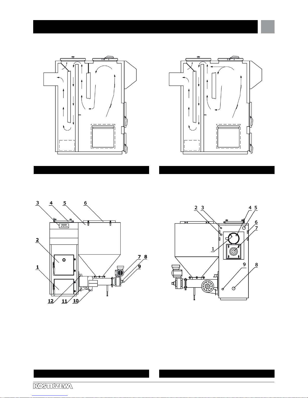
Ash pan door
Door for cleaning burner
and grate installation
Boiler control system
Top charging door
Fuel tank
Fuel charging hole to tank
Motor with gear unit
(gear-motor)
1.
2.
3.
4.
5.
6.
7.
Locking pin (screw
connecting worm with
gear unit)
Fuel feeder (worm)
Ignition fan
Pressure fan
Fuel ignition heater
8.
9.
10.
11.
12.
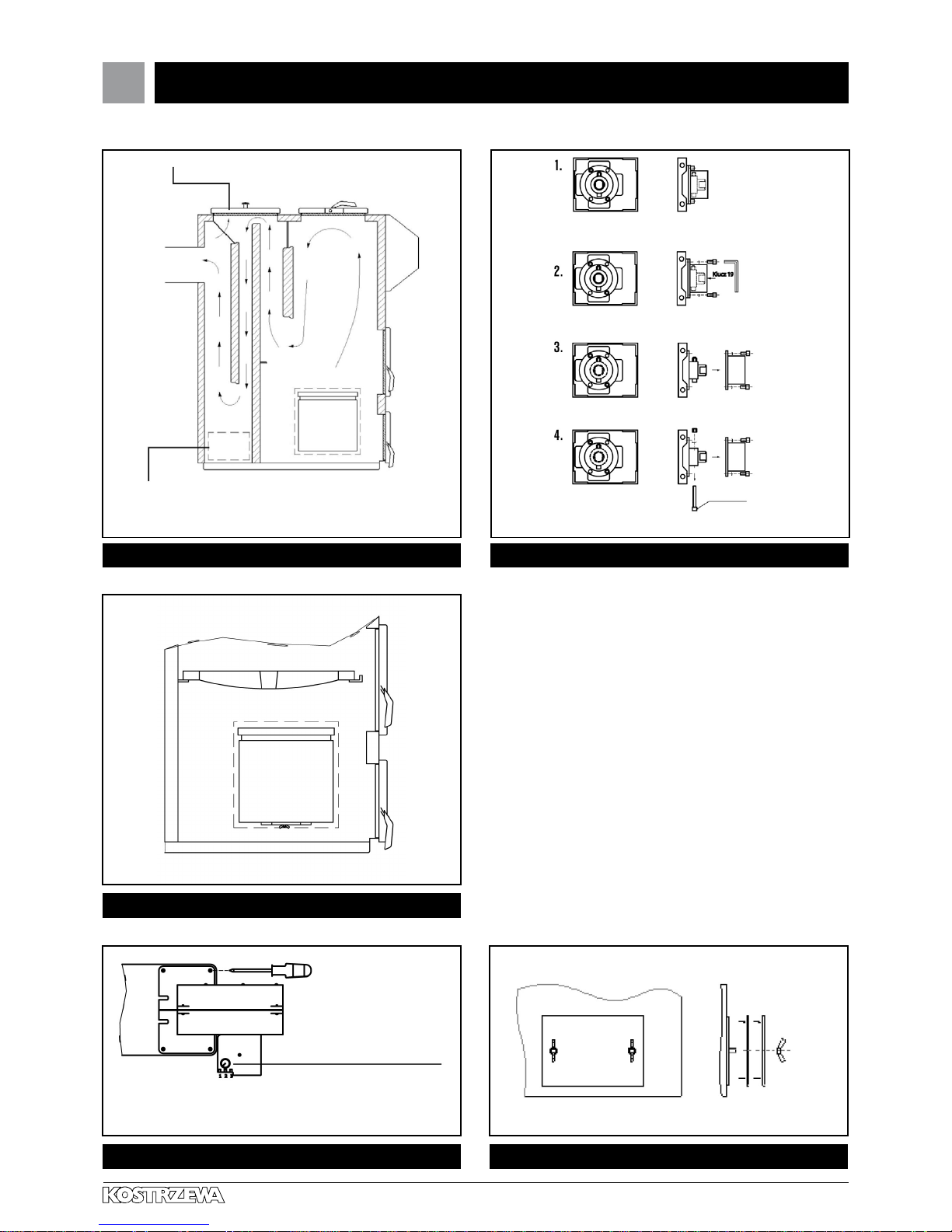
4. Description of Pellets Fuzzy Logic Boiler design
Fig. 01 Flue gas circulation in boiler exchanger Fig. 02 Flue gas circulation in boiler exchanger
Fig. 03 Boiler design Fig. 04 Boiler design
Lambda probe
Boiler thermal protection
Boiler sensor, thermal
protection 95°C
Flue gas sensor
Heating medium outlet
from boiler
1.
2.
3.
4.
5.
Wiring system ducts
Exhaust fan
Heating medium
return to boiler
Water drain
6.
7.
8.
9.
7
Pellets Fuzzy Logic - Service Manual- ENGV 10.11
Experts in biomass heating
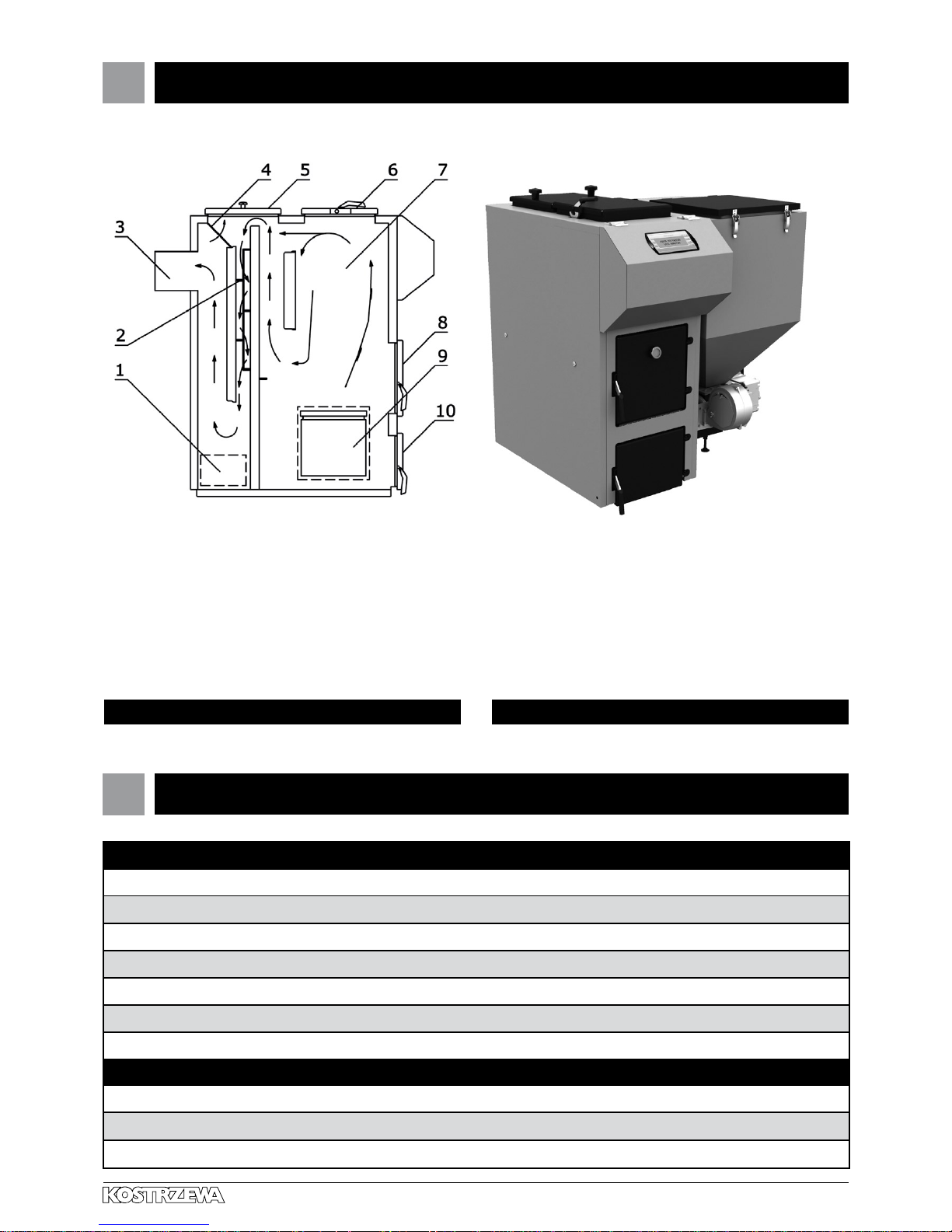
4. Description of Pellets Fuzzy Logic Boiler design cont.
Standard accessories:
Boiler service and installation manual (1pcs.)
Cast iron grates (set.)
Flue gas turbulator (1 pc.)
Room controller (1 pc.)
External sensor (1 pc.)
Domestic hot water sensor (1 pc.)
Central heating sensor (1 pc.)
Auxiliary accessories:
Lambda probe module (1 pc.)
Floor heating control module (additional heating circuits) (1 pc.)
Solar system control module (1 pc.)
Boiler clean out
Flue gas swirl vanes
Flue gas outlet (chimney)
Access to clean the third
baffle
Cleanout upper door
Charging door for wood
1.
2.
3.
4.
5.
6.
Charging (combustion)
chamber
Access door to
burner and grate
Air chamber of the burner
with the clean-out at
the bottom part
Ash pan door
7.
8.
9.
10.
Fig. 05 Boiler design Fig. 06 Pellets Fuzzy Logic Boiler
5. Pellets Fuzzy Logic accessories.
8
8

Pellets Fuzzy Logic - Service Manual- ENGV 10.11
Experts in biomass heating
6. Protecting and control equipment
Boiler equipment allows
the user to set:
boiler temperature
temperature in the heating circuit according
to the room temperature
domestic hot water temperature (full weather control)
room temperature
temperature of water returning from the central heating system.
(the function protecting the boiler exchanger);
igniter heating time (depending on the fuel type)
operation of the fuel feeder and three fans;
manual control of the feeder and fan;
automatic burner output modulation (fuzzy logic)
automatic air dosage (lambda sensor module)
It is possible to connect the executive modules MU1 to the control
system. Each of those modules controls the five heating circuits
or controlled room thermostats. The module of additional heating
circuits (control of mixing valves). The solar module to control the
solar collector.
Thermal sensor
The mechanical protecting device is mounted in the boiler
and protects the heating system from overheating. If it is set to 95°C,
it means that above this temperature the feeder and fans will be
turned off and the central heating and domestic hot water pumps
start operation.
Room controller with optional programming
(in 7-days cycle)
The digital room thermostat with programming option is used to
automatic control of heated rooms.
Fuzzy Logic control method
Advantages of Fuzzy Logic control:
Fuzzy logic algorithm is more advanced than „pid” algorithm
used in other appliances ;
Reduction of combusted fuel quantities;
Eliminates formation of impurities and tar in the boiler
to a great extent;
High temperature stability of the boiler operation
– eliminates water vapor dripping in the boiler;
Combustion chamber temperature is high and stabile,
thereby the emissivity of carbon oxides is reduced.
•
•
•
•
•
•
•
•
•
•
•
•
•
•
•
Lambda probe
Voltage generated by the cell is transmitted to the Pellets Control
controller governing the fuel-air mixture composition in the boiler.
This module continuously adjusts the fuel mixture composition, to
ensure the most perfect operation of the device under the determined conditions of the boiler load, fuel type and weather conditions and to minimize the emission of carbon monoxide. A properly
adjusted air-fuel mixture can save up to 20% of fuel. Control takes
place continuously during the entire cycle of the boiler operation.
Locking pin at the feeder inlet
Located at the beginning of the worm conveyor shaft. Possible
blockage of the worm conveyor causes the compression of the
above component, thereby protecting the engine from damage (after
breaking the locking pin clean the burner knee, insert a new locking
pin and start up the boiler).
Automatic motor thermal sensor
It is located in the control system housing at the back of the boiler
and protects the motor from damage. When the load is not large
enough to break the protective device on the feeder clutch and the
motor is under greater and greater load and begins to heat up, the
automatic thermal sensor trips off the motor. To restart the motor,
press the button No. 1.
Temperature sensor on the worm conveyor cover
In the event of the flame (heat) reversal to the feeder it transmits a
signal to the boiler controller, which in turn switches off the combustion air fan and forces the feeder operation to remove the heat out
of the feeder. This protection works only when the boiler is supplied
with electricity.
Flue gas sensor
It is mounted in the chimney flue and measures the flue gas temperature.
When the exhaust temperature is above 230 ° C, clean the boiler
heat exchanger.
Central heating and domestic hot water pump.
It works according to a proper algorithm,
so as to make optimum use of heat.
Mixing valve actuator
This component is used to preset the heating circuit temperature in
the central heating system while maintaining a constant temperature
in the boiler. The temperature is calculated from the heating curve,
external temperature and room temperature.
9

Pellets Fuzzy Logic - Service Manual- ENGV 10.11
Experts in biomass heating
7. Pellets Fuzzy Logic Boiler location and installation
7.1 Regulations, standards
and recommendations
The boiler room should meet the conditions of the building law
in force at the site of the boiler installation. In Poland, these
provisions are treated by the standard PN-B-02411, and the
regulation of the Minister of Infrastructure of 12 April 2002 on the
technical requirements to be met by buildings and their location.
(Journal of Laws No. 75, item. 690)”. The solid-fuel fired boilers
should be installed in separated plant rooms and the fuel storage
should be located in a separate plant room near the boiler or in the
room in which the boiler is installed, however not closer than 40 cm
from the boiler. The boiler room should meet the requirements of fire
protection and OH&S regulations.
7.2 Recommended boiler room
dimensions
The height of the room shall not be less than two heights
of the boiler, however, not less than 2,5 m;
The distance between the wall and the boiler unit min. 100 mm;
The distance between the tank and wall min. 600 mm;
The distance from the rear wall of the boiler to the wall should
be min. 300 mm;
The distance from the front wall should be min. 400 mm;
7.3 Positioning on a
non ammable oor
Boiler should be set on a non-flammable heat insulating pad,
which should be greater than the base of the boiler by 2 cm
from each side of the boiler;
If the boiler is located in the basement, we recommend to set
the boiler on the foundation of at least 5 cm in height. The boiler
must be positioned vertically.
7.4 Safe distance
from ammable materials
During installation and operation of the boiler keep
a safe distance of 20 cm from flammable materials;
In case of flammable materials of C3 flammability degree,
which are quick and easy to burn even after removal of ignition
sources (such as paper, paperboard, cardboard, wood,
plastics), the said distance is doubled, ie. to 40 cm;
If flammability is not known, the safe distance should
also be doubled.
•
•
•
•
•
•
•
•
•
•
7.5 Ventilation of the boiler room
Air delivery shall take place through the non-closed hole with the
minimal cross-section of 200 cm² and the exit to 100 cm above the
floor level.
7.6 Chimneys
Chimneys are designed to remove flue gas to the outside in a reliable
manner and draw the air for combustion. The chimney draft necessary
for this purpose is conditional on:
temperature difference between hot flue gas and cold air;
effective height of the chimney;
chimney cross-section (≥ 100 cm²);
chimney execution (possibly smooth internal surfaces)
and the tightness of joints;
The effective chimney height is the height difference between the
highest furnace and the chimney outlet. The effective height of
individual chimneys must be at least of 4 m, and in the case of the
common chimneys for solid and liquid fuels it must be at least of
5 m. The height difference between the two furnaces cannot be
greater than 6.5 m.
In the case of sloping roofs the chimneys should terminate within the
ridge (the highest edge of the roof), in the area of free movement of
wind, thereby avoiding draft interferences and disturbing effect on
and by the environment. You should always pay attention to the
location of the building in relation to other buildings.
•
•
•
•
Flammability degree of building
compounds and products
Building materials
and products
A – noncombustible sandstone, concrete, bricks,
fire-protection plaster, mortar,
ceramic tiles, Granite
B - slow-burning wood-cement boards,
glass fiber, mineral Insulation
C1 – slow-burning beechwood, oak wood,
Plywood
C2 - moderately-burning pine, larch and spruce wood,
cork, Sawn wood planks,
Rubber floor lining
C3 - easily-burning Asphaltic board, celluloid
compounds, polyurethane,
Polystyrene, polyethylene,
plastic, etc.
10

Pellets Fuzzy Logic - Service Manual- ENGV 10.11
Experts in biomass heating
7. Pellets Fuzzy Logic Boiler location and installation cont.
7.7 Selection of a chimney
In most cases, the selection of a chimney based on an approximate
method or chimney manufacturer’s diagrams is sufficient. In special
cases (adverse pressure and temperature dependence; large volume
of flue gas) the chimneys are calculated according to BS EN 13384-1
(PN-EN 13384-1).
The diagrams of chimneys contain such input values as the chimney
conduction thermal resistance, roughness of the chimney inner
walls, flue conduction thermal resistance and coefficients
of hydraulic resistance when changing directions of the tubes.
The diagrams of the manufacturers include the relationship between
the rated capacity of the heating unit and the effective height of the
chimney for the various cross-sections of the chimney.
The diagrams will vary depending on the used fuel (eg. oil, gas,
wood), design of furnaces (eg. pressure boiler with a fan burner),
flue gas temperature and type of load.
7.8 Chimneys for solid
fuel-red boilers
It should be noted that the solid fuel-fired furnaces with a rated
thermal output > 20 kW and w/o fan need their own chimney.
For the solid fuel-fired boiler the cross-section of the chimney should
be 16cm x 16cm (in Poland - at least 14cm x 14 cm). When the
cross-section is different, then the flue gas flows too slow and cools
down too much. This in turn leads to problems with the draft and
formation of deposits in the chimney. These deposits damage the
wall, if sulfuric acid and water vapor contained in flue gas cool below
the dew point temperature.
For the solid fuel-fired furnaces the single-layer chimneys made
from brick, often occurring in old buildings, can be used. Currently
the three-layer chimneys with a smooth surface and good thermal
insulation are applied.
7.9 Flue
The flues according to DIN 18160, connect a boiler with
a chimney. They can be made as the exhaust pipes or as flue gas
ducts. Exhaust pipes are the pipes and fittings, which are distributed
in the premises. Flue gas ducts comply with the fire-protection
requirements for chimneys and are often made from the same
material as the main chimney. The connecting units should be
as short as possible and placed with an upslope to the chimney
to avoid heat losses and additional resistance. They can not be lead
onto other floors. Exhaust pipes should not be laid in the rooms,
in which the furnaces cannot be mounted, besides they also should
not be mounted in the walls and ceilings.
7.10 Installation and commissioning
The solid fuel-fired boiler must be installed in accordance with
applicable regulations by an authorized service company. The boiler
commissioning must be carried out by trained service staff of the
manufacturer possessing an appropriate license.
7.11 Connecting to the heating
system
The hydraulic system should comply with the applicable regulations
and standards and must be performed according to building-art
principles.
7.12 Requirements for heating
system water:
Water must be transparent and colorless w/o additives and
other chemically aggressive substances;
Water hardness below 20 of
PH above 8.5
7.13 Connecting to the wiring system
The boiler is designed for supplying voltage 230V/50Hz. Installation
should be performed by a qualified person with an easy access to
the connecting socket of 230V/10A, grounded. Boiler and boiler
room lighting system should have a different power supply circuit.
•
•
•
11

Pellets Fuzzy Logic - Service Manual- ENGV 10.11
Experts in biomass heating
7. Pellets Fuzzy Logic Boiler location and installation cont.
NOTE!!!
To ensure optimum performance and proper
combustion it is required that chimney draft represent
the appropriate values from Table No. 1
Due to low flue gas temperature, in order to protect
the chimney from moisture and reducing the draft,
it is advised to use the chimney inserts from acid-resistant
steel or ceramics with condensate discharge
to a floor drain.
NOTE!!!
In order to avoid the „dew formation” in the ash
pan chamber it is recommended to set the boiler on the
thermally insulated floor or put the insulating material
under the boiler (for boilers without a double-insulated
bottom).
NOTE!!!
Central heating system connected to the boiler must
be fitted with a drain cock, which must be at the lowest
point and as close to the boiler as possible.
8. Boiler commissioning – Instructions for AS
12
8. Boiler commissioning –
instructions for A.S.
Commissioning of the boiler must be carried out only by the
service personnel trained by the manufacturer, with a current
certificate of an authorized service performer of Kostrzewa
company.
Completion of installation and heating test performance must
be recorded in the Warranty Card.
The completed warranty card should be mailed by the user
to the address of the manufacturer to register the user in the
company system.
•
•
•
SERWIS KOSTRZEWA
ul. Przemysłowa 1, 11-500 Giżycko, POLAND
woj. warmińsko – mazurskie
tel. 087 428 53 51
e-mail: serwis@kostrzewa.com.pl
12

Pellets Fuzzy Logic - Service Manual- ENGV 10.11
Experts in biomass heating
9. Boiler control system user manual
As per controller service manual enclosed on page 29 - Pellets Control M Fuzzy Logic
10. While using the Platinum Bio Burner, keep in mind ....
13
The boiler can be operated only by adult persons familiarized
with the above service manual. Children cannot stay close to
the boiler without presence of adult persons.
When it comes to penetration of flammable gases or vapors
to the boiler room or during the work, at which an increased
risk of fire or explosion occurs (gluing, painting, etc.) the boiler
should be switched off before starting the work.
When cleaning the deposit in the knee, the device must be
switched off (OFF position).
It is prohibited to use flammable liquids to fire up the boiler,
the boiler must be fired up automatically.
When adding fuel to the boiler tank the device should be turned
off (OFF position).
When cleaning the boiler, it must be switched off (OFF position).
Flame can be visually controlled by means of a sight glass
incorporated in the door.
During operation, the boiler cannot be overheated.
•
•
•
•
•
•
•
•
Do not place any flammable objects on the boiler or in its
immediate vicinity.
When removing ash from the boiler any flammable materials
cannot be present in a distance of 1500mm to the minimum
from the boiler. Ash should be deposited into the fireproof
tanks with a cover.
During operation of the boiler at a temperature lower than 60°C
the dew formation on the steel heat exchanger may occur and
thereby the corrosion due to low temperature, which shortens
the life of the heat exchanger. Therefore, the temperature during
operation of the boiler must be at least 60°C.
After the heating season, clean the boiler and smoke duct
thoroughly. Keep the boiler room in clean and dry condition.
Any tampering with electrical part or changing the boiler design
are prohibited.
•
•
•
•
•
13

Pellets Fuzzy Logic - Service Manual- ENGV 10.11
Experts in biomass heating
11. Boiler start up – instructions for user
11.1 First start up of the boiler
Pour the fuel into the tank (pellets, pea coal, cereal);
Select fuel type;
Set the OFF mode on the controller panel;
Feed the fuel to the burner with a manual fuel feeding function;
Feed the fuel until it appears on the burner bottom (knee);
Set the ON mode on the control panel;
After more then ten minutes the flame will appear, which can be
seen via the sight glass on the boiler door.
11.2 Boiler damping
In the case of the planned longer standstill of the boiler set the
controller panel into OFF mode.
11.3 Starting up the boiler
after fuel depletion
Remove carbon deposits from the burner knee -
applies only to pellets;
Pour the fuel into the tank (pellets, pea coal, cereals);
Set the OFF mode on the control panel;
Feed the fuel to the burner with a manual fuel feeding function;
During feeding at the feeder turned off remove unburnt fuel
from the knee manually (if the unburned fuel is not removed,
your feeder may be blocked and the locking screw (feeder
locking pin) may be broken);
Feed the fuel until pure granulate appears at the bottom of the
burner;
Set the ON mode on the control panel;
After more then ten minutes the flame will appear, which can be
seen via the sight glass on the boiler door.
•
•
•
•
•
•
•
•
•
•
•
•
•
•
•
11.4 Starting up the boiler after
the feeder locking pin rupture.
Remove carbon deposits from the burner knee - applies only to
pellets;
In case of pea coal – remove a large coal lump between the
tank and fuel feeder, removing the worm from the feeding tube;
Pour the fuel into the tank (pellets, pea coal, cereal);
Set the OFF mode on the control panel;
Feed the fuel to the burner with a manual fuel feeding function;
During feeding with the feeder turned off remove unburnt fuel
from the knee manually (if the unburned fuel is not removed,
your feeder may be blocked and the locking screw (feeder
locking pin) may be broken);
Feed the fuel until pure granulate appears at the bottom
of the burner;
Set the ON mode on the control panel;
After more then ten minutes the flame will appear, which can be
seen via the sight glass on the boiler door.
11.5 Starting up the boiler
with wood as a fuel
NOTE!!!
During wood combustion make sure that the flu gas
temperature does not exceed 200°C.
Set the OFF mode on the control panel;
Select the fuel type – charging chamber;
Place additional grates in the boiler;
Put the pieces of paper on the grate;
Put the dry wood piece on the grate;
Fire up the paper pieces using matches;
Close the boiler door;
Set the boiler panel into the ON mode;
Set the boiler preset temperature to 70°C;
Add some dry wood after several hours;
•
•
•
•
•
•
•
•
•
•
•
•
•
•
•
•
•
•
•
14

Pellets Fuzzy Logic - Service Manual- ENGV 10.11
Experts in biomass heating
11. Boiler start up – instructions for user cont.
11.6 Setting up the burner for pellets,
pea coal and cereals.
The burner parameters should be set according to Table 3
(a number of the below tables belonging to the table no 3)
Instruction for setting the burner for pellets, cereal*, pea coal.
NOTE!!!
If the boiler is equipped with a lambda probe
it is recommended to use the flue gas analyzer to set
its characteristic. When setting up the blower output
for the subsequent boiler outputs (as described below)
the number of oxygen units should be recorded.
In the chimney-sweep mode for the output at 100%, the blower
was set to 50, you should check the number of oxygen units.
Note this value to be able to enter the proper value to the probe
characteristic later;
Set the boiler output to 100%;
Go to the advanced settings and select the chimney
sweep mode (yes). For proper output volumes ranging from
20%, 40%, 60%, 80%, 100%, pre-set the output of the blower;
Start up the boiler in the chimney-sweep mode at 100% output,
match the output of the blower. If the blower output is properly
matched, the pellets should be between the upper and lower
row of the burner holes, the flame should be high and clear,
and no smoke should be present in the combustion chamber.
When the flame is low, with bright yellow color and the pellet
is getting black, increase the fan output by 4 units and wait
for 0 min. until the furnace operation stabilization;
If the air is adjusted properly for 100%, then remaining in the
chimney-sweep mode, change the output to 80% and match
the air in accordance with the earlier procedure;
proceed the same way for 60%, 40% and 20%. If all operations
were carried out according to the instructions above, set the
required temperature of the boiler operation and turn on the
boiler (ON).
In the case of pea coal fuel firing the proper method of combustion
will be as follows: the flame is high, transparently yellow, and pea
coal will be present approximately 3 cm above the upper edge of the
burner (a small pile).
•
•
•
•
•
•
15

Pellets Fuzzy Logic - Service Manual- ENGV 10.11
Experts in biomass heating
11. Boiler start up – instructions for user cont.
11.6 Setting up the burner for pellets, pea coal and cereals cont.
Table 03 part 01
NOTE!!!
When the fuel falls out unburned increase the amount of air and / or reduce the burner output !
Technical parameters of Pellets® Fuzzy Logic - Pellets
RPM
Boiler output [kW] Feeding [s] Standstill [s]
0,9 15 2,5 10
0,9 20 3,3 10
0,9 25 4,1 10
0,9 30 5,0 10
0,9 35 5,8 10
0,9 40 6,6 10
0,9 45 7,4 10
1,8 / 3,6 50 4,1 10
1,8 / 3,6 55 4,5 / 2,3 10
1,8 / 3,6 60 5,0 / 2.5 10
1,8 / 3,6 65 5,4 / 2,7 10
1,8 / 3,6 70 5,8 / 2,9 10
1,8 / 3,6 75 6,2 / 3,1 10
1,8 / 3,6 80 6,6 / 3,3 10
1,8 / 3,6 85 7,0 / 3,5 10
1,8 / 3,6 90 7,4 / 3,7 10
1,8 / 3,6 95 7,8 / 3,9 10
1,8 / 3,6 100 8,2 / 4,1 10
It is necessary to correctly set the air according to feeding and standstill times
(air surplus coefficient 2.0-2.4) developed in the company Kostrzewa® Sp.j.
16

Pellets Fuzzy Logic - Service Manual- ENGV 10.11
Experts in biomass heating
11. Boiler start up – instructions for user cont.
Table 03 part 02
NOTE!!!
When the fuel falls out unburned increase the amount of air and / or reduce the burner output !
Technical parameters of Pellets® Fuzzy Logic - Pea coal
RPM Boiler output [kW] Feeding [s] Standstill [s]
0,9 15 1,7 10
0,9 20 2,2 10
0,9 25 2,8 10
0,9 30 3,4 10
0,9 35 3,9 10
0,9 40 4,5 10
0,9 45 5,0 10
1,8 / 3,6 50 2,8 / 1,4 10
1,8 / 3,6 55 3,1 / 1,5 10
1,8 / 3,6 60 3,4 / 1,7 10
1,8 / 3,6 65 3,6 / 1,8 10
1,8 / 3,6 70 3,9 / 1,9 10
1,8 / 3,6 75 4,2 / 2,1 10
1,8 / 3,6 80 4,5 / 2,2 10
1,8 / 3,6 85 4,8 / 2,4 10
1,8 / 3,6 90 5,1 / 2,5 10
1,8 / 3,6 95 5,4 / 2,7 10
1,8 / 3,6 100 9,7 / 2,8 10
It is necessary to correctly set the air according to feeding and standstill times
(air surplus coefficient 2.0-2.4) developed in the company Kostrzewa® Sp.j.
17

Pellets Fuzzy Logic - Service Manual- ENGV 10.11
Experts in biomass heating
11. Boiler start up – instructions for user cont.
Table 03 part 03
Power output Pellets Pea coal
P15 or P14
(Pellets Lambda Control)
Burner output Blower output Oxygen Burner output Blower output Oxygen
100% 35 130-160 100% 40 130-160
80% 30 140-170 80% 35 140-170
60% 25 150-180 60% 30 150-180
40% 20 160-190 40% 25 160-190
20% 18 160-190 20% 22 160-190
P25
100% 45 130-160 100% 50 130-160
80% 40 140-170 80% 45 140-170
60% 35 150-180 60% 40 150-180
40% 30 160-190 40% 25 160-190
20% 28 160-190 20% 32 160-190
P40 or P30
(Pellets Lambda Control)
100% 45 130-160 100% 55 130-160
80% 40 140-170 80% 50 140-170
60% 35 150-180 60% 45 150-180
40% 30 160-190 40% 40 160-190
20% 28 160-190 20% 38 160-190
P50
100% 45 130-160 100% 55 130-160
80% 40 140-170 80% 50 140-170
60% 35 150-180 60% 45 150-180
40% 30 160-190 40% 40 160-190
20% 28 160-190 20% 37 160-190
P75
100% - 130-160 100% - 130-160
80% - 140-170 80% - 140-170
60% - 150-180 60% - 150-180
40% - 160-190 40% - 160-190
20% - 160-190 20% - 160-190
P100
100% - 130-160 100% - 130-160
80% - 140-170 80% - 140-170
60% - 150-180 60% - 150-180
40% - 160-190 40% - 160-190
20% - 160-190 20% - 160-190
18
Pellets Fuzzy Logic - Service Manual- ENGV 10.11
Experts in biomass heating
11. Boiler start up – instructions for user cont.
Sustaining
pea coal
Sustaining
standstill ( min )
Sustaining
feeder ( s )
Sustaining
Blower rundown ( s )
Sustaining
Blower output ( % )
for p15, p25, P40 20 17 90 40
for p50, p75, P100 20 12 90 40
* suggested minimum burner output 40%;
* with P15, P25, P40 models the pressure fan output at pos. 1 (the lowest rpm);
• with P50, P75 models the pressure fan output at pos. 2, 3
• for each device select the maximum burner output for a given fuel ( PFL burner setting)
Table 03 part 04
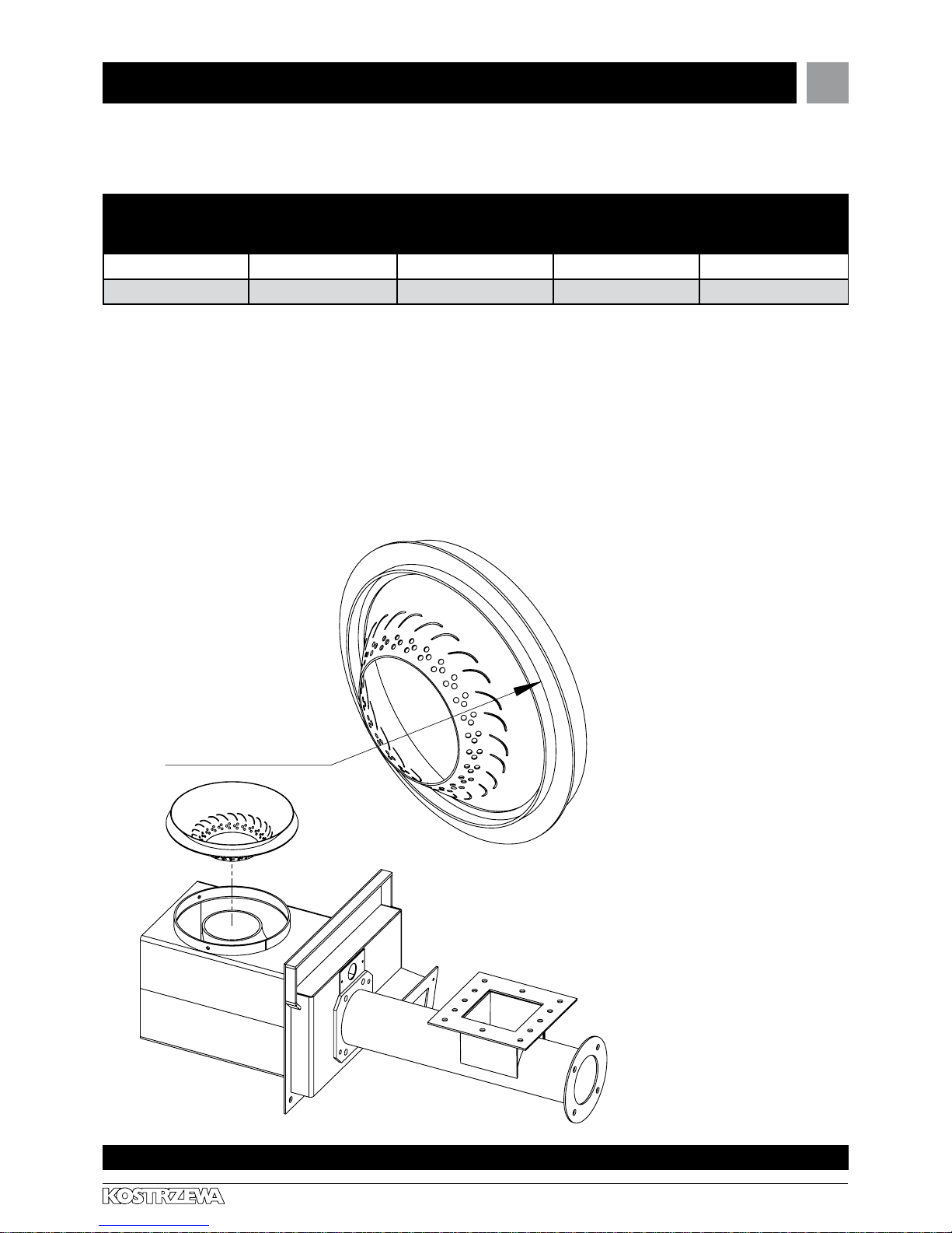
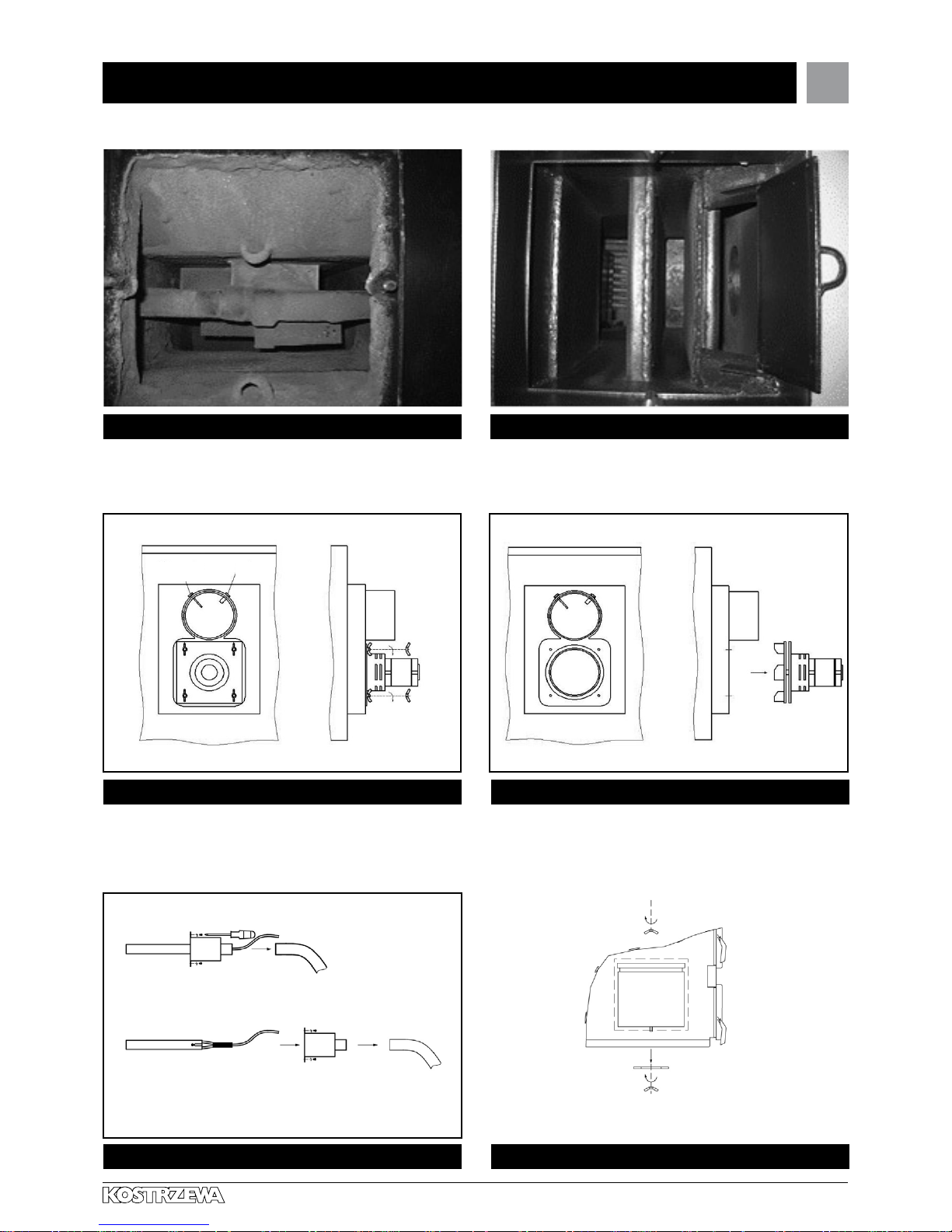
11.7 Mounting the burner tip
uszczelnić silikonem
Fig. 07 Mounting the burner tip
seal with silicone
19
Pellets Fuzzy Logic - Service Manual- ENGV 10.11
Experts in biomass heating
11. Boiler start up – instructions for user cont.
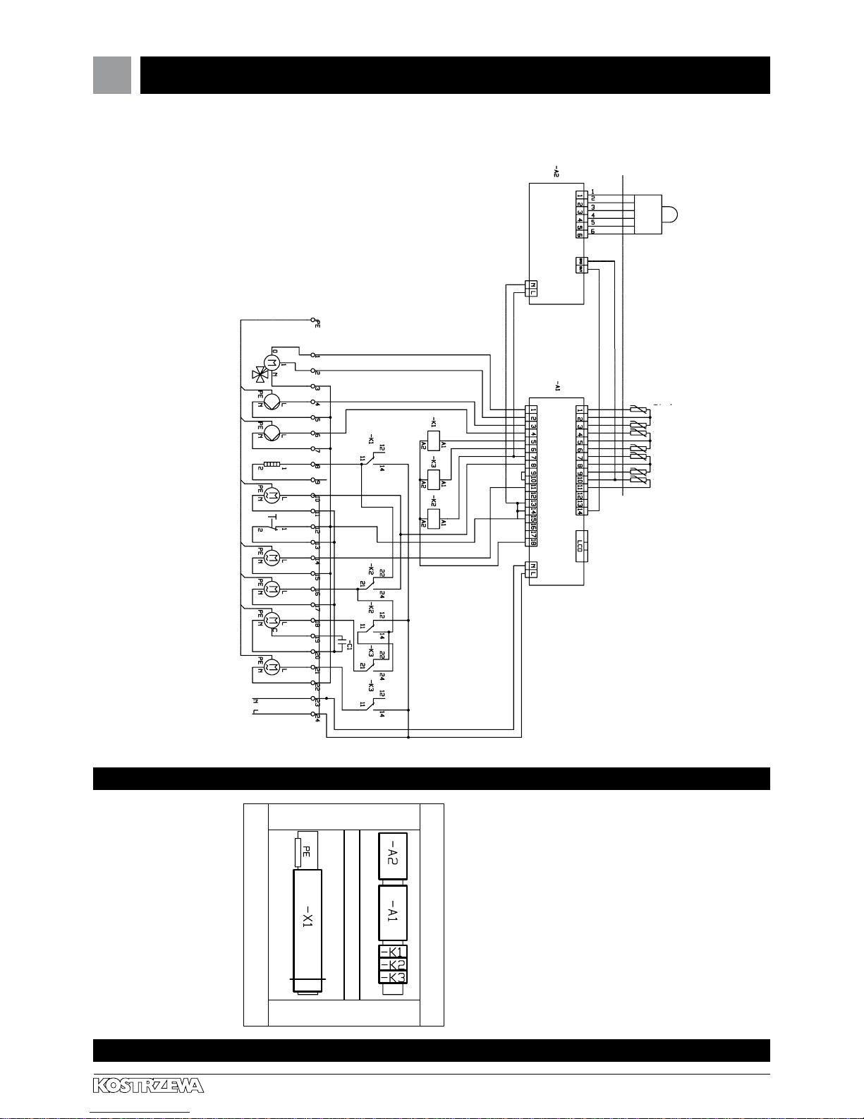
11.8 Switchgear diagram
Fig. 09 View of facade
Fig. 08 Switchgear diagram
silnik mieszacza
pompa c.w.u.
sonda lambda
szerokopasmowa
T c.w.u
T podajnika
T co
T powrotu*
silnik czyszczenia
zasilanie 230V~
seal with silicone
DHW pump
CH pump
igniter
main blower
thermal switch
feeder motor
igniter / blower
exhaust fan
cleaning motor
supply voltage 230 V
Lambda probe
Lambda module ML-2
outside the switchgear
boiler temp
DHW temp.
Feeder temp.
flue gas temp.
ambient temp
CH temp.
return temp
Pellets Control M
NOTE!!!
If the module ML - 2 is connected,
disconnect the probe return temp.
20

Pellets Fuzzy Logic - Service Manual- ENGV 10.11
Experts in biomass heating
11. Boiler start up – instructions for user cont.
11.10 Symptoms of abnormal
combustion
unburnt pellets overflow out of the burner; flame is very
short; boiler chamber is full of smoke – check the times
of feeding and standstill, increase the air volume by 2 units,
wait 10 minutes; adjust (add)the air for so long, until the flame
is high and bright, and no smoke will be present
in the combustion chamber;
unburnt pellets „jump” out of the burner, the flame is very
sharp and high, the chamber of the boiler is not smoky,
pellets are below the level of the upper air holes – check
the times of feeding and standstill, decrease the air volume by
2 units, wait 10 minutes; adjust (reduce) the air for so long,
until the flame is high and bright, and no smoke will be present
in the combustion chamber;
•
•
unburnt pea coal overflows out of the burner, despite
of correct combustion process – reduce the burner output
(feeding and standstill times);
unburnt pea coal overflows out of the burner, flame is
very short, the chamber of the boiler is smoky –
check the times of feeding and standstill, increase the air
volume by 2 units, wait 10 minutes, adjust (add)the air for so
long, until the flame is high and bright, and no smoke will be
present in the combustion chamber.
•
•
12. Cleaning and maintenance
12.1 Cleaning and maintenance
Regularly clean the ash pan chamber;
Regularly clean the clean-out chamber;
Regularly clean the burner chamber;
Regularly clean the exhaust fan;
Regularly clean the boiler exchanger;
•
•
•
•
•
Regularly clean the burner knee
Regularly clean the carbon deposits off the lambda probe with a
soft brush after every 100 hours of operation - only the pellets;
At least once a year, call for AS to perform an annual boiler
inspection - obligatory inspection;
•
•
•
NOTE!!! Boiler cleaning can be performed only
when the device is disconnected from the mains.
!
!
21
21

Pellets Fuzzy Logic - Service Manual- ENGV 10.11
Experts in biomass heating
12. Cleaning and maintenance cont.
Fig. 10 Cleaning the burner knee off carbon deposits (only for pellets)
Fig. 11 Cleaning the burner knee off carbon deposits (only for pellets)
Fig. 12 Cleaning the Lambda probe
Fig. 13 Very dirty combustion chamber. Fig. 14 Very clean combustion chamber.
Igniter orfice Carbon deposit
Lambda probe
Flue gas temp. sensor
Flue gas temp. sensor
22
Pellets Fuzzy Logic - Service Manual- ENGV 10.11
Experts in biomass heating
12. Cleaning and maintenance cont.
Fig. 19 Igniter replacement Fig. 20 Boiler chamber cleaning
Fig. 15 Very dirty boiler exchanger Fig. 16 Very clean boiler exchanger
Fig. 17 Exhaust fan disassembly - cleaning. Fig. 18 Exhaust fan disassembly - cleaning.
Flue gas
temp. sensor
Lambda
probe
23
Pellets Fuzzy Logic - Service Manual- ENGV 10.11
Experts in biomass heating
12. Cleaning and maintenance cont.
Fig. 21 Exchanger cleaning Fig. 22 Locking pin replacement in motoreducer gear unit
Fig. 23 Grate layout
Fig. 24 Pressure fan optional settings Fig. 25 Boiler cleanout opening method
Lid for exchanger cleaning
Lid for sooth removal from exchanger
Allen key No. 6
Loking pin / 8.8 hardness class
Three fan outputs
24

Pellets Fuzzy Logic - Service Manual- ENGV 10.11
Experts in biomass heating
13. Troubleshooting
Failure type Probable reason for failure Probable reasons/ suggested remedy
The device does not turn on the igniter
- ZAP message does not appear
on the controller display
Sensor improperly inserted into
connection block;
Flue gas sensor damaged.
Flue gas temperature on the
display 630 o C.
•
•
Check correctness of sensor
connection in the connection block;
Replace flue gas sensor.
Ignite fuel manually.
•
•
The message „feeder overheating”
flashes on the display. The feeder is cold
Sensor improperly inserted into
connecting block;
Feeder sensor damaged.
Feeder is working all the time.
•
•
Check correctness of sensor
connection in the connecting block;
Replace the feeder sensor.
•
•
No readings on the controller display No power supply;
Incorrect connection of plugs
and cables of the controller;
too much moisture in the controller.
•
•
•
Check the boiler connection to
power supply source;
Check correctness of
plugs installation and connections
of the controller.
•
•
One of the control panel push-buttons is
out of service.
Control panel failure.• Control panel repair.•
Worm conveyor does not rotate despite
of signalized activation.
Gera-motor is not powered;
Improper connection of
supplying cables;
Feeder blockade;
Gear-motor failure;
Control module failure.
•
•
•
•
•
Check correctness of
plugs installation and connections
of the controller Module;
Check correctness of connections
between gear-motor and worm
shaft;
Check the efficiency of feeder
channel and the freedom of rotation
of the worm shaft in the feeder
channel;
Check or replace the condenser
(once per year replace
the condenser with the new one).
•
•
•
•
Locking pin breaking (multiple). Hard material is clogged between
the tank and feeder;
Carbon deposit on the burner
knee (only for pellets);
Worn worm tip (pellets com out
heavily mixed).
•
•
•
Remove the worm from the feeder
and remove hard element;
Hammer out the carbon deposits
from the edge of the burner knee
and restart the feeder (without
removing the worm);
Insert a new worm.
•
•
•
25

Pellets Fuzzy Logic - Service Manual- ENGV 10.11
Experts in biomass heating
13. Troubleshooting cont.
Failure type Probable reason for failure Probable reasons/ suggested remedy
Automatic fuel ignition does not operate. Improper settings of the heater
heating time and fire test;
Improper heater connection;
Clogged outlet hole of hot air from
the heater.
•
•
•
Change setting parameters;
Check correctness of connections
of the heater plugs and conduits
(including the connecting blocks);
Open the igniter orifice;
Very moist fuel;
Damaged heater
(it does not heat up itself ).
•
•
•
•
•
During combustion a lot of dark smoke
appears in the boiler chamber.
A lot of unburned fuel drops to the ash
pan.
Air volume set improperly;
Feeding and standstill times set
improperly for individual output
values.
•
•
Increase the amount of air, check
the feeding and standstill times
(burner output can be set
too high ).
•
During combustion a great quantity of
flying fuel pieces is present in the boiler
chamber. Great quantity of unburnt fuel
drops to the ash pan.
Air volume set improperly;
Feeding and standstill times set
improperly for individual output
values.
•
•
Diminish the amount of air, check
the feeding and standstill times
(burner output can be set too high )
•
Boiler does not come up to the preset
temperature.
Boiler incorrectly matched with the
building;
Failure of sensors;
the temperature sensor of the water returning to the boiler is situated
improperly;
Boiler output set too low.
•
•
•
•
Check correctness of boiler
matching;
Check the sensors;
Check the location of the return
sensor (water circulation shall be
present in this place);
Check the feeding and standstill
times of the burner;
•
•
•
•
Smoke liberates from the boiler. Clogged flue;
Clogged boiler extension duct;
Clogged exchanger channels.
•
•
•
Open the channels.•
14. Instructions for boiler disposal after expiration of its service life
26
Due to the fact that components of the boiler are made up of different materials, you can transfer them to the collection point of secondary raw
materials, ensuring proper utilization of steel, plastics, etc.
26
Pellets Fuzzy Logic - Service Manual- ENGV 10.11
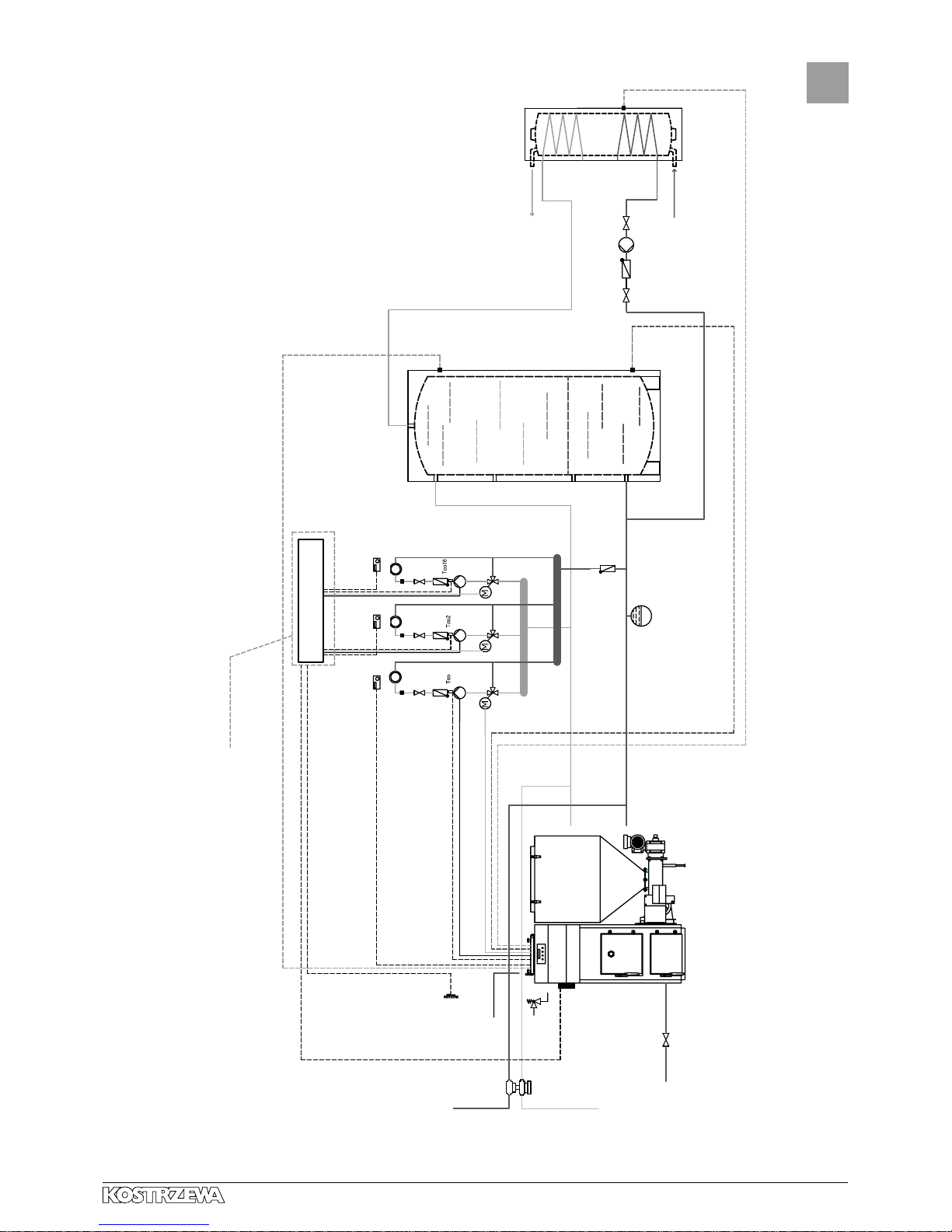
Experts in biomass heating
Pellets Fuzzy Logic boiler connection diagram
Zasilanie
instalacja c.o.
(zimna woda)
Spust wody
z instalacji c.o.
Pellets Fuzzy Logic
Zasilanie 230V
Unicontrol Mix
Czujnik temp.
pokojowej 1
CTP-01/CTP-02
Czujnik
bufor
góra
Czujnik
c.w.u.
Pompy
Zimna woda
Czujnik temp.
pokojowej 2
CTP-01/CTP-02
Obwód grzewczy 1
Obwód grzewczy 2 Obwód grzewczy 16
Czujnik temp.
pokojowej n
CTP-01/CTP-02
Hot water
Cold water
DHW
sensor
Pumps
Buffer sensor
on top
Buffer sensor
at the bottom
room temperature
sensor n
CTP- 01/CTP - 02
room temperature
sensor 2
CTP- 01/CTP - 02
Unicontrol Mix
heating circuit 16heating circuit 2
heating circuit 1
Pellets Fuzzy Logic
spust wody
z instalacji c.o.
outflow
zasilanie instalacja c.o.
(cold water)
external
temperature
sensor CTZ - 01
supply
voltage 230 V
boiler
temperature
sensor
Moduły rozszerzeń
UWAGA!!!
Aby zrealizować wszystkie funkcje ukladu należy dokupić dodatkowe moduły.
room temperature
sensor 1
CTP- 01/CTP - 02
27

Pellets Fuzzy Logic - Service Manual- ENGV 10.11
Experts in biomass heating
Czujnik
pokojowy
Czujnik c.o.
Ogrzewanie
Pompy
Czujnik c.w.u.
Zimna woda
Zasilanie
instalacja c.o.
(zimna woda)
Zasilanie 230V
Spust wody
z instalacji c.o.
Pellets Fuzzy Logic
Pellets Fuzzy Logic boiler connection diagram
DHW sensor
Hot water
Cold water
Pumps
Pellets Fuzzy Logic
external temperature
sensor CTZ - 01
supply voltage 230 V
spust wody
z instalacji c.o.
outflow
zasilanie instalacja c.o.
(cold water)
Heating
Mixing valve
CH sensor
room controller
28
Pellets Fuzzy Logic - Service Manual- ENGV 10.11
Experts in biomass heating
Boiler controller service manual.
Pellets Fuzzy Logic
The Second Generation
29

Pellets Fuzzy Logic - Service Manual- ENGV 10.11
Experts in biomass heating
Introduction
Pellets Fuzzy Logic The Second Generation boiler controller is a
modern microprocessor system, which controls not only the boiler,
but also the central heating system in weather and domestic hot water
mode.
The device controls the volume of fuel fed through the cyclic operation
of the feeder motor and the quantity of air supplied to the combustion
process. Thanks to application of solid state relays the blower output
is regulated smoothly and the reliability of the control system of the
feeder motor is increased many times.
Automatic fuel ignition. Pellets Fuzzy Logic The Second Generation
controller allows to automatically ignite the fuel in the retort.
Measurement of flue gas temperature. The controller will allow reading
the flue gas temperature, which is essential at the boiler operation with
automatic lighting up. Knowing the flue gas temperature is also very
helpful in monitoring and control of the boiler.
Weather control provides the maximum thermal comfort, because
the heating medium temperature is adjusted as a function of outdoor
temperature. Adjustment is done by mixing valve actuator.
Application of the temperature sensor of the heating medium returning
from the installation to the boiler reduces water vapor condensation in
the boiler and increases its life. Thanks to the advanced algorithm and
the possibility of adjusting many parameters, the system can be very
flexibly adapted to the needs of the heating system.
The controller is fitted with the output testing function. This function is
available in SERVICE MODE and allows you to check the correctness
of electrical connections and efficiency of executive modules (pumps,
blower, feeder, mixing valve actuator) before starting the boiler.
A large alphanumeric display facilitates communication between the
device and the user and the operation is very simple. The new intuitive
menus in several languages: Polish, English, German, French.
The lambda sensor ensures proper dosage of air into the
combustion process, which significantly simplifies operation, reduces
fuel consumption and improves combustion and thereby reduces
the emissions of harmful substances to environment (optional boiler
equipment).
15. General
30
 Loading...