

Page 1
Textanker_Kapitel
Installation guide
PIKO MP plus with
KOSTAL Smart Energy Meter and
BYD Battery-Box Premium HVS/HVM
Page 2

Legal notice
KOSTAL Solar Electric GmbH
Hanferstraße 6
79108 Freiburg i. Br.
Germany
Phone +49 (0)761 477 44 - 100
Fax +49 (0)761 477 44 - 111
www.kostal-solar-electric.com
Exclusion of liability
All names, trademarks, product names or other
designations used in this manual may be legally
protected even if not indicated as such (e.g. as a
trademark). KOSTAL Solar Electric GmbH assumes no
liability or warranty for their free usage. The illustrations
and texts have been compiled with great care. However,
the possibility of errors cannot be ruled out. The
compilation is made without any guarantee.
General note on gender equality
KOSTAL Solar Electric GmbH is aware of the importance
of language with regard to the equality of women and
men and always makes an eort to reflect this in the
documentation. Nevertheless, for the sake of
readability we are unable to use non-gender-specific
terms throughout and use the masculine form instead.
© 2020 KOSTAL Solar Electric GmbH
All rights reserved by KOSTAL Solar Electric GmbH,
including those of reproduction by photocopy and
storage in electronic media. Commercial use or
distribution of the texts, displayed models, diagrams and
photographs appearing in this product, is not permitted.
This manual may not be reproduced, stored, transmitted
or translated in any form or by means of any medium, in
whole or in part, without prior written permission.
Valid from:
PIKO MP plus: HMI 3.14
KOSTAL Smart Energy: SW 1.3.0
© 2021 KOSTAL Solar Electric GmbH
2
Page 3
Installation guide
You can find this installation guide in our download area for the PIKO MP plus under Operating
manual.
The installation guide does not replace the operating instructions or manuals for the inverter,
battery and KOSTAL Smart Energy Meter required for correct assembly and installation.
IMPORTANT INFORMATION
Installation may only be carried out by a trained and qualified electrician!
Follow the safety instructions in the operating instructions for the inverter, battery and KOSTAL Smart Energy
Meter.
A battery activation code for the KOSTAL Smart Energy Meter and a computer / tablet are required to put the
storage system into full operation and to make all the necessary settings.
For all work on the devices or on the supply lines, the power supply in the house, the inverter and the battery
must be completely de-energized. Take a look at the corresponding operating instructions for the respective
devices (inverter / battery / KOSTAL Smart Energy Meter).
The installation of data and signal lines is standardized according to: VDE 0800-174-2 / Part 2: Information
technology; Installation planning and practices in buildings, VDE 0100-443 protection against overvoltages
due to atmospheric influences or switching operations and VDE 0100-444 protection against interference
voltages and electromagnetic interference. The separation between power lines and data / signal lines must
be ensured by spacing for reasons of electromagnetic compatibility and functionality.
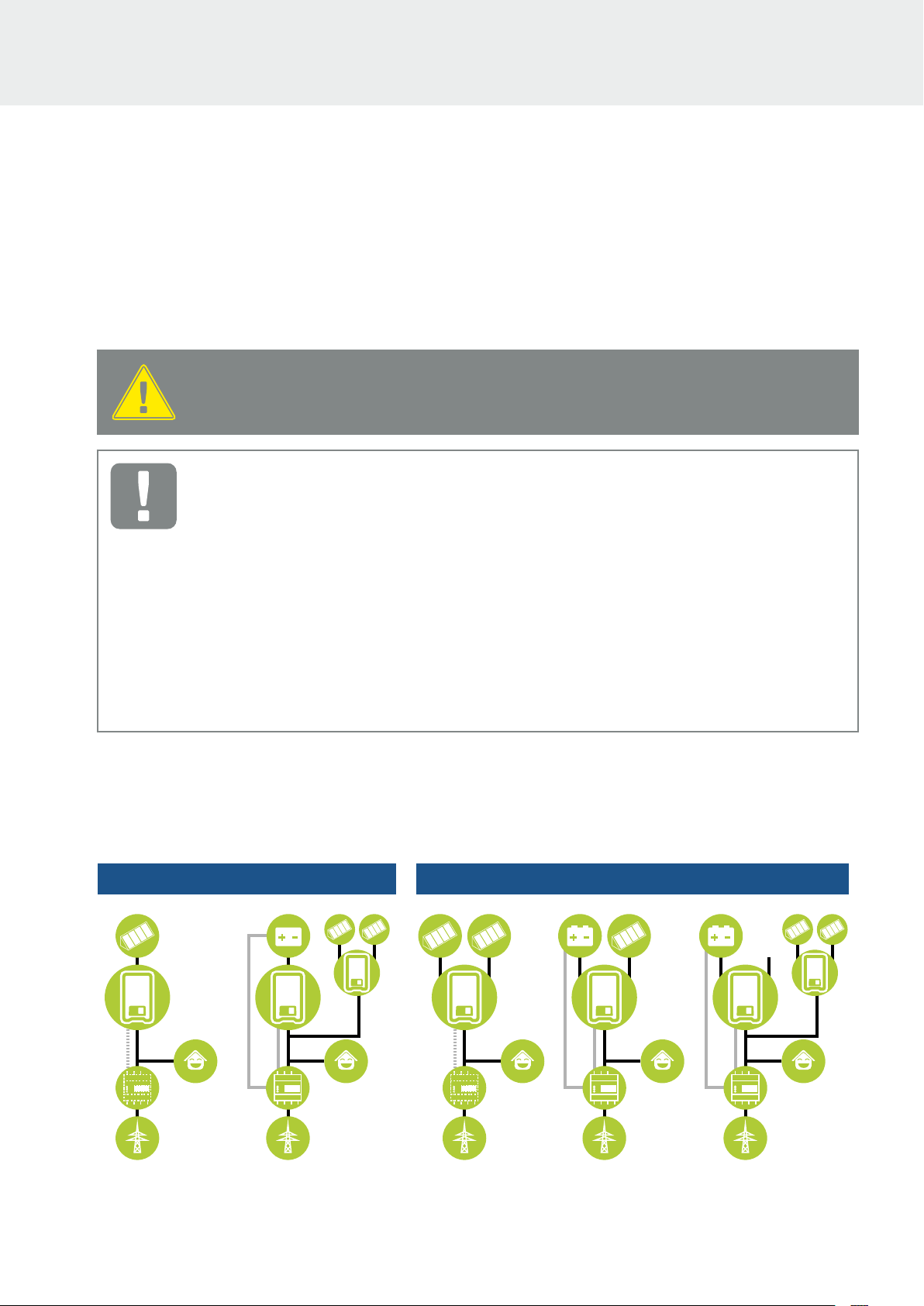
PIKO MP plus applications
The PIKO MP plus can be used as a PV inverter, battery inverter or as a hybrid inverter with and without
a battery.
PIKO MP plus da 1.5 a 3.6 con 1 inseguitore MPP PIKO MP plus da 3.0 a 5.0 con 2 inseguitori MPP
PIKO MP plus 1.5 to 3.6 with 1 MPP tracker PIKO MP plus 3.0 to 5.0 with 2 MPP trackers
PV inverter PV inverter Hybrid inverter Battery inverter
KOSTAL Smart
Energy Meter
1) Second DC input not connected.
Battery inverter
KOSTAL Smart
Energy Meter
KOSTAL Smart
Energy Meter
KOSTAL Smart
Energy Meter
1)
KOSTAL Smart
Energy Meter
© 2021 KOSTAL Solar Electric GmbH
3
Page 4

Sequence of installation and commissioning
The following software is required for the PIKO MP plus function with battery. You can find these in the
download area for the PIKO MP plus.
n
PIKO MP plus: HMI 3.14.0 / PU-APP 4.1.43 / ENS 1.35 / PAR 23.0.12
n
KOSTAL Smart Energy: 1.3.0
The following sequence must be observed when installing and commissioning the entire system to
avoid errors.
1. Install the KOSTAL Smart Energy Meters (KSEM) energy meter according to the operating
instructions.
2. Install the PIKO MP plus inverter according to the installation instructions and switch on the the AC
side.
3. Install the BYD Battery-Box Premium HVS / HVM battery according to the operating instructions and
preconfigure it with the BYD-APP.
4. Set the inverters DC switch to OFF (0).
5. Switch o the battery by pressing the power button (min. 6 sec.) on the front.
6. Switch on the battery using the main switch on the side of the BCU.
7. Set up the inverter and battery in the KOSTAL Smart Energy Meter (KSEM).
8. Set the inverters DC switch to ON (|).
Switch-on sequence after error
The following sequence must be followed if an error has occurred or the battery was switched o
manually during operation using the circuit breaker on the battery.
1. Set the inverters DC switch to OFF (0).
2. Switch o the battery by pressing the power button (min. 6 sec.) on the front (if it is still switched on).
3. Switch on the battery using the main switch on the side of the BCU.
4. Set the inverters DC switch to ON (|).
© 2021 KOSTAL Solar Electric GmbH
4
Page 5
PIKO MP plus xx-2: DC2 - PV / Bat
PIKO MP plus xx-2: DC1 - PV
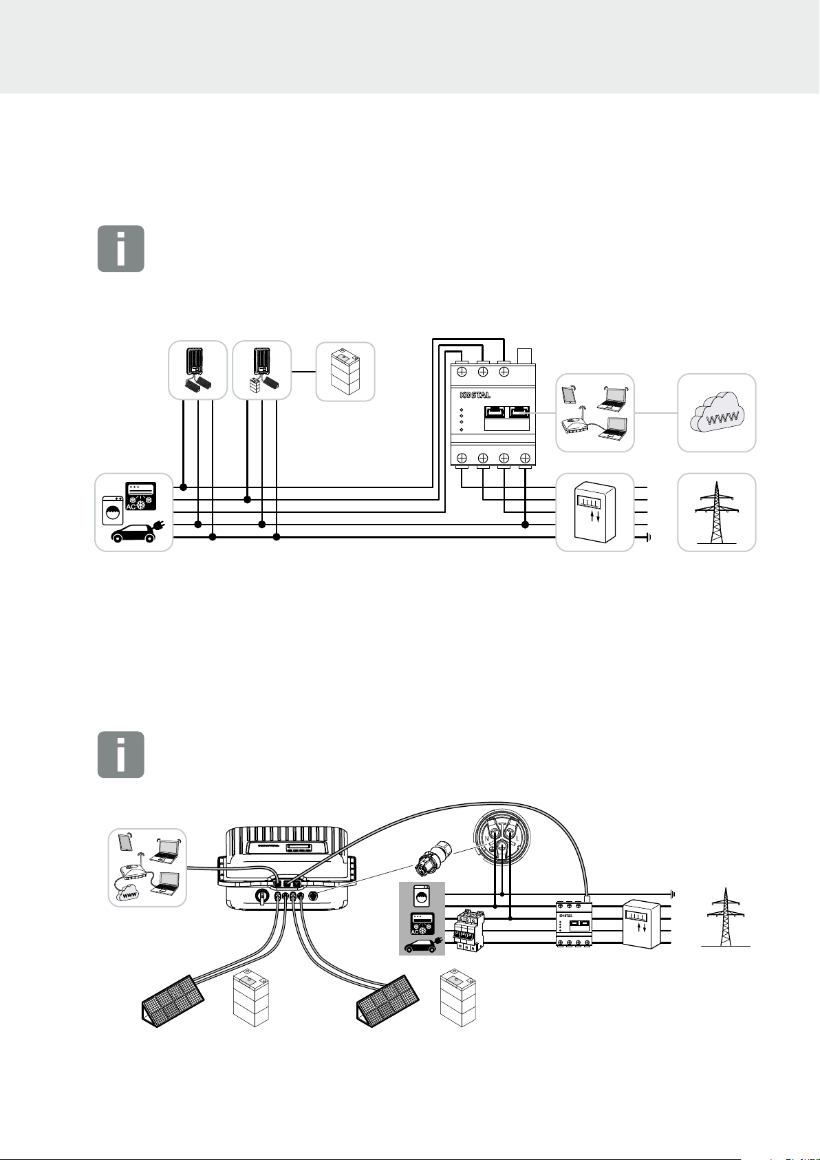
Installation of KOSTAL Smart Energy Meters for battery operation
INFO
Use the KOSTAL Smart Energy Meter instruction manual for the complete installation.
It is impotant that the KOSTAL Smart Energy Meter is installed at the grid connection point.
When the battery input in the PIKO MP plus is activated, the installation position of the KOSTAL Smart
Energy Meter is fixed to the grid connection point and cannot be changed.
BMS
DC-x
BMS
L1 L2 L3
STATUS
NETWORK
SERIAL BUS
REST
L1 L2 L3 N
Modbus
Smart Energy Meter
LAN
LAN
RS485
L1
L2
L3
N
PE
1. Install KOSTAL Smart Energy Meter as shown at the grid connection point.
2. Establish a LAN connection from the KOSTAL Smart Energy Meter, battery and inverter to the
Internet.
3. In this variant, the KOSTAL Smart Energy Meter runs as a master and sends data to the inverter and
battery.
Installation of PIKO MP plus for battery operation
INFO
Use the PIKO MP plus instruction manual for the complete installation.
Router / network
Visualization via
KOSTAL Solar Portal
KOSTAL Solar App
PIKO MP plus xx-1: DC1 - PV / Bat
© 2021 KOSTAL Solar Electric GmbH
BMS
or or
L1 L2 L3
Smart Energy Meter
LAN
STATUS
NETWORK
SERIAL BUS
REST
L1 L2 L3 N
KOSTAL Smart Energy Meter
BMS
CAT 5e / max. 15m
RS485
Modbus
LAN
PE
N
L1
L2
L3
5
Page 6
KOSTAL Smart Energy Meter
PIKO MP plus
BYD Battery Box Premium
DC + DC -
CAT 5e / max. 15m
CAT 5e / max. 15m
ON
1 2 3 4 5 6 7 8
INVERTER
COM
ETHERNET
RS485CAN
OFF
CAN
RS485
COM
P+ P-
31 2
875 64321
RS458-A
RS458-B
GND
RS485
Modbus
LAN
L1 L2 L3
L1 L2 L3 N
LAN
STATUS
NETWORK
SERIAL BUS
REST
Smart Energy Meter
B
VCC
GND
A
4 3 2 1
RS485 (A)
A
B
87654321
1
8
DCx
PIKO MP plus x.x-1 > DC1
PIKO MP plus x.x-2 > DC2
875 64321
COM 1/RJ45
VCC
GND
A
B
4 3 2 1
RS485 (B)
87654321
1
8
875 64321
A B
GND
ON OFF
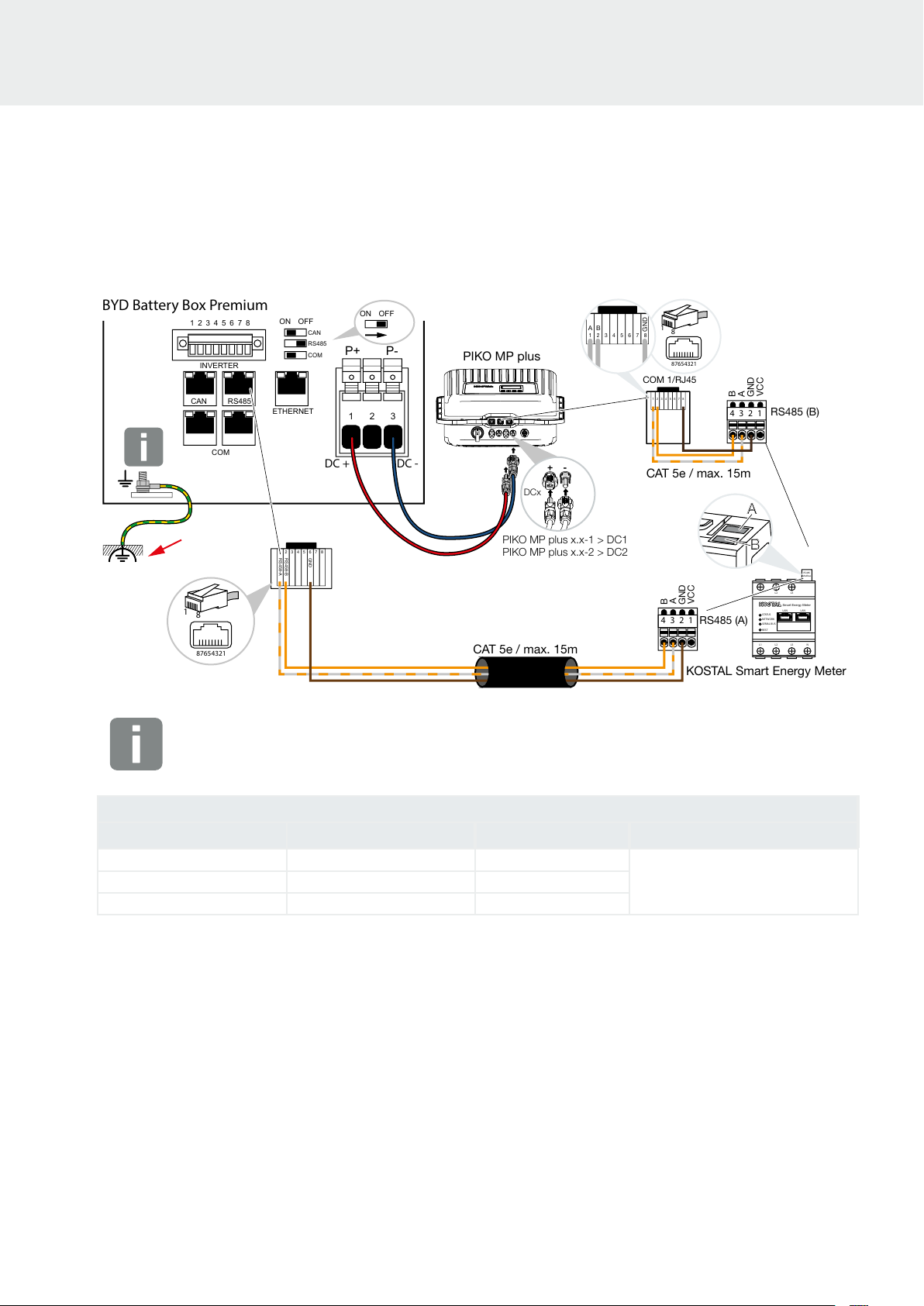
Connection of PIKO MP plus PIKO MP plus /
Batterie BYD Battery Box Premium / KOSTAL Smart Energy Meter
Connection via RJ45 connector
BYD Battery-Box Premium KOSTAL Smart Energy Meter Connection Cable
1. Establish and connect the RS485 communication line between the inverter and the KOSTAL Smart
Energy Meter RS485 (B).
2. Establish and connect communication line RS485 between battery and KOSTAL Smart Energy
Meter RS485 (A).
3. Set the terminating resistor of the RS485 interface in the battery to OFF.
4. Connect the DC cables of the battery to the inverter.
© 2021 KOSTAL Solar Electric GmbH
IMPORTANT!
Connect the battery earth (BCU) to the equipotential earth connection.
1 3 RS485 A
2 4 RS485 B
6 2 GND
min. Cat.5e / Twisted pair
max. Ø 6,8mm / max.15m
6
Page 7
Commissioning of the entire system
Commissioning configuration of the inverter and DC input for battery
1.
Commission the PIKO MP plus inverter according to the inverter installation manual and carry out
the initial configuration.
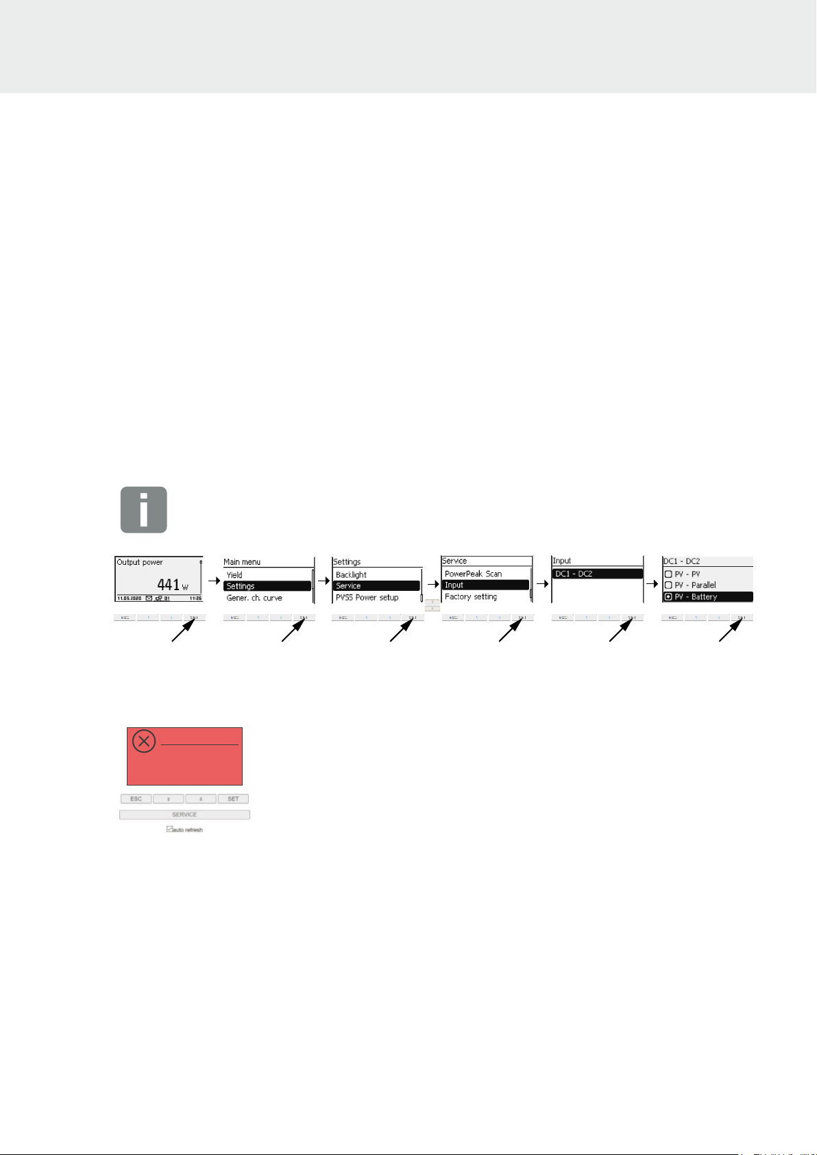
2. Switch the DC input in the inverter to battery. By default, the inputs are set to PV. To switch the DC
input to battery, press the SET button in the main menu of the inverter under Settings > Service >
Inputs > DCx and select the battery. Exit the menu with the ESC key. The DC input is now switched
to battery.
DCx = DC1 for PIKO MP plus xx-1 (AC-storage mode with 1 MPP tracker)
DC1 - DC2 for PIKO MP plus xx-2 (AC- or hybrid storage mode with 2 MPP trackers)
INFO
To access the service menu, press the arrow keys and on the keyboard simultaneously for
a few seconds in the Service menu.
P
After this configuration, the display of the inverter lights up in red and shows the following error
message because the inverter and the battery in the KOSTAL Smart Energy Meter have not yet been
configured.
11.05.2020
Energy manager:
01 /120
No
NEW
Communication
3. Set the inverters DC switch of the PIKO MP plus to OFF (0).
4. Switch on the battery using the main switch on the side of the BCU.
5. Open the web server of the KOSTAL Smart Energy Meter via the internet browser. To do this, you
can call up the KOSTAL Smart Energy Meter (KSEM) appearing on your PC via the file explorer
under Devices.
10:35
ACTIVE
© 2021 KOSTAL Solar Electric GmbH
7
Page 8
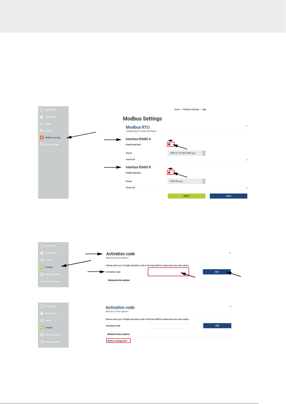
6. In the KOSTAL Smart Energy Meter menu, call up the menu item „Modbus settings“> „Modbus
RTU“ and deactivate both RS485 interfaces and confirm with Save.
7. In the KOSTAL Smart Energy Meter menu, call up the menu item „Inverter“ > „Activation code“. The
activation code, which is subject to a charge, must be purchased in advance via our web shop
shop.kostal-solar-electric.com
8. Enter the previously purchased activation code for the battery function under the „Activation code“
item.
xxxxxxxxxxxxxxxxxxxx
P
The „Battery management“ field then appears under „Activated additional options“.
© 2021 KOSTAL Solar Electric GmbH
8
Page 9
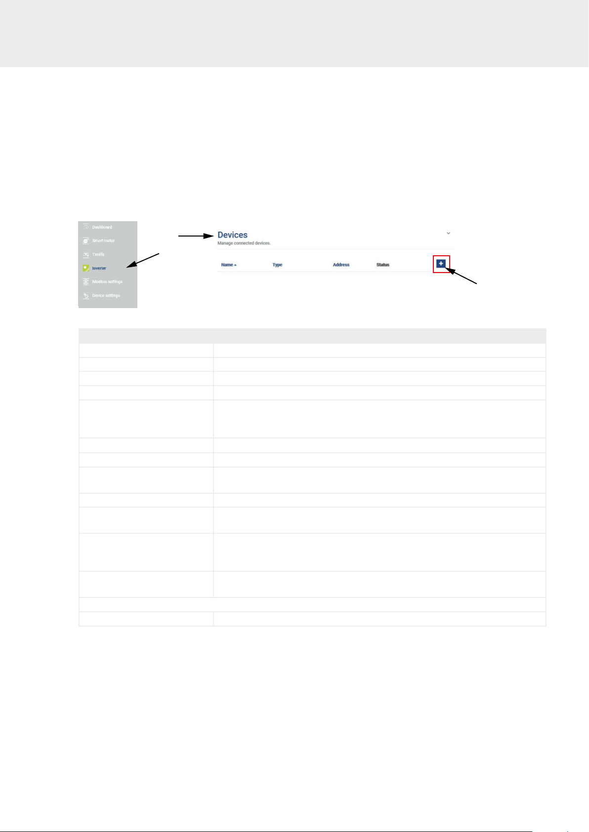
9. In the KOSTAL Smart Energy Meter menu, call up the menu item „Inverters“ > „Devices“ and add a
new device using .
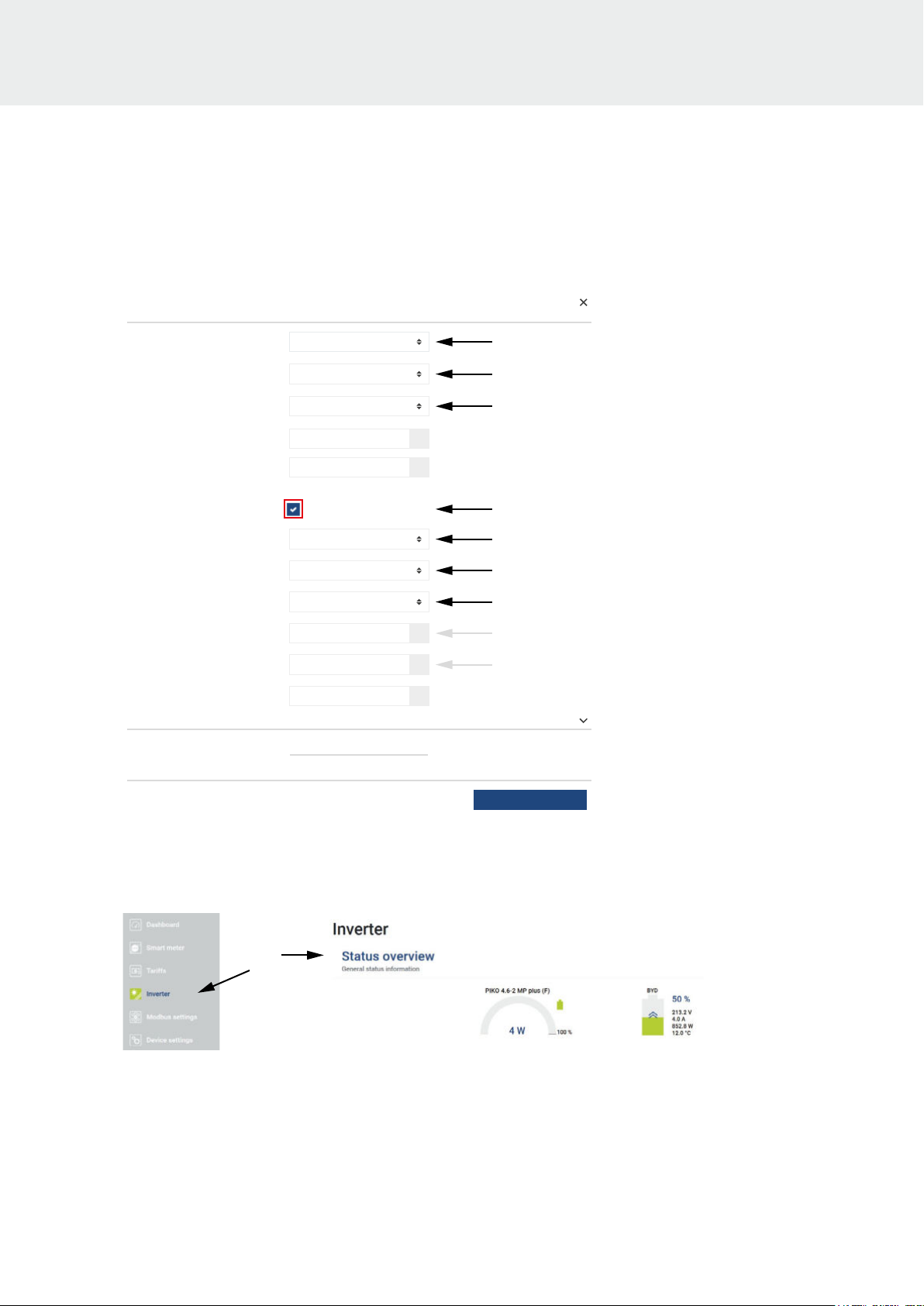
10. Enter values for new devices and confirm with OK.
Parameter Value
Series Select PIKO MP plus.
Type Select the power class of the inverter e.g. B. PIKO MP plus 4.6-2.
Serial interface Select RS485 B
Timeout Does not have to be changed.
Max. AC output power of
inverter
Battery management
Serial interface of battery Select RS485 A
Battery type
Number of modules Specify the number of battery modules installed in the battery (e.g. 5).
Max. SOC (charging status)
Min. SOC (charging status)
Nominal charge/discharge
power of battery
Advanced
RS485 adress Enter 1
Does not have to be changed.
The max. The output power of the inverter is set automatically by the above selection
(e. g. for PIKO MP plus 4.6-2 = 4600).
Enable battery support
Select the battery type that is connected to the PIKO MP plus
(e.g. BYD HVS or BYD HVM).
Set the desired value for max. battery charge state (default 100%). The battery is
charged up to this SOC value.
Set the desired value for min.x battery depth of discharge (default 5%). The battery
is discharged up to this SOC value. Note the information provided by the battery
manufacturer (BYD Battery = 5%).
Does not have to be changed.
The value is automatically set by the battery information above.
© 2021 KOSTAL Solar Electric GmbH
9
Page 10
Add new device
Series PIKO MP plus
Type PIKO MP plus 4:6-2
Serial interface RS485 B
Timeout
Max. AC output power of inverter
Battery management
battery
Advanced
RS485 adress
60
4600 W
Enable battery support
RS485 ASerial interface of Battery
BYD HVM PremiumBattery type
5Number of modules
100Max. SOC (charging status)
5Min. SOC (charging status) %
3330Nominal charge/discharge power of
1
S
%
W
OK
11. Set the DC switch on the PIKO MP plus inverter to ON (|).
12. In the inverter view under „Status overview“ all values of the battery including the state of charge are
shown.
© 2021 KOSTAL Solar Electric GmbH
10
Page 11
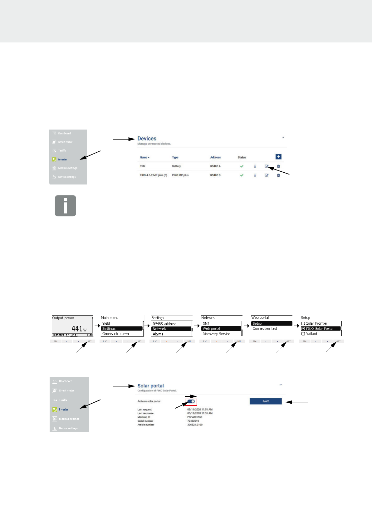
13. The two devices - inverter and battery - are displayed in the inverter view under „Devices“.
INFO
If the SOC for the battery is to be changed, this can be done via the modify button (pin) in the battery
device line.
14. Finally, the transfer of the data to the KOSTAL Solar Portal must be set up.
Set up data transfer to the KOSTAL Solar Portal
The yield data of the overall system can be called up via the KOSTAL Solar Portal or the KOSTAL Solar
App. To do this, the inverter and the KOSTAL Smart Energy Meter must be configured to send data to
the KOSTAL Solar Portal.
1. The transfer of data (yield data) is activated in the PIKO MP plus as follows:
2. The transfer of data (house consumption, self-consumption and battery values) is activated in the
KOSTAL Smart Energy Meter via the menu item „Inverter „Solar Portal“.
© 2021 KOSTAL Solar Electric GmbH
11
Page 12
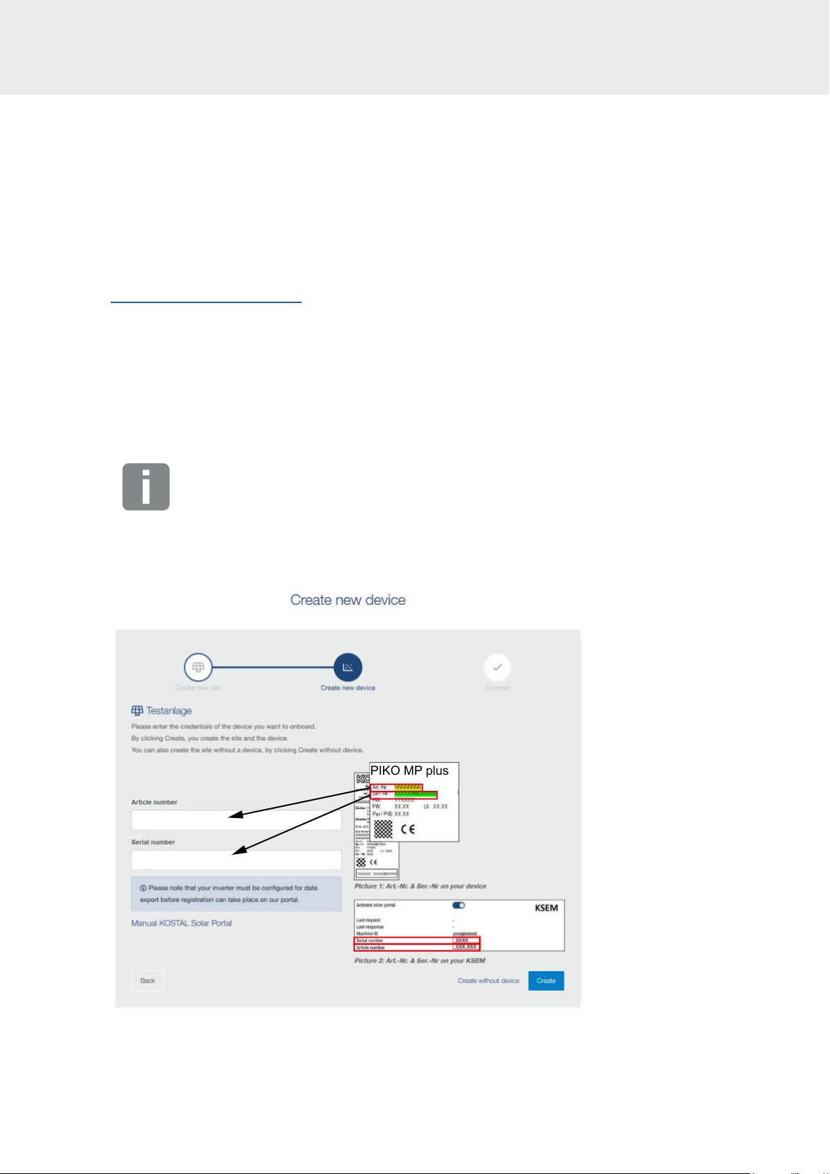
PIKO MP plus
3. Set up the PIKO MP plus inverter and the KOSTAL Smart Energy Meter in the KOSTAL Solar Portal
www.kostal-solar-portal.com.
4. To set up a device, a system must first be created. To do this, click the „Create new system“ button
under the „System overview“ section.
5. Enter the data for the system and click on „Create“.
6. In the next window, enter the article number and the serial number. Click on “Create”. The inverter
and KOSTAL Smart Energy Meter must be added to the same system.
INFO
With the PIKO MP plus you will find the necessary data (article number / serial number) on the type
label.
With the KOSTAL Smart Energy Meter, please use the data from the internal web server of the
KOSTAL Smart Energy Meter, which can be found under Inverters > Solar Portal.
H
Commissioning of the entire system has now been completed.
© 2021 KOSTAL Solar Electric GmbH
12
Page 13

Textanker_Kap
KOSTAL Solar Electric GmbH
Hanferstr. 6
79108 Freiburg i. Br.
Deutschland
Telefon: +49 761 47744 - 100
Fax: +49 761 47744 - 111
KOSTAL Solar Electric Ibérica S.L.
Edificio abm
Ronda Narciso Monturiol y Estarriol, 3
Torre B, despachos 2 y 3
Parque Tecnológico de Valencia
46980 Valencia
España
Teléfono: +34 961 824 - 934
Fax: +34 961 824 - 931
KOSTAL Solar Electric France SARL
11, rue Jacques Cartier
78280 Guyancourt
France
Téléphone: +33 1 61 38 - 4117
Fax: +33 1 61 38 - 3940
KOSTAL Solar Electric Hellas Ε.Π.Ε.
47 Steliou Kazantzidi st., P.O. Box: 60080
1st building – 2nd entrance
55535, Pilea, Thessaloniki
Ελλάδα
Τηλέφωνο: +30 2310 477 - 550
Φαξ: +30 2310 477 - 551
KOSTAL Solar Electric Italia Srl
Via Genova, 57
10098 Rivoli (TO)
Italia
Telefono: +39 011 97 82 - 420
Fax: +39 011 97 82 - 432
KOSTAL Solar Electric Turkey
Mahmutbey Mah. Taşocağı Yolu
No:3 (B Blok), Ağaoğlu My Oce212,
Kat:16, Ofis No: 269
Bağcılar - İstanbul / Türkiye
Telefon: +90 212 803 06 24
Faks: +90 212 803 06 25
www.kostal-solar-electric.com
05 / 2021 - EN - DOC02568066-0002 - Subject to technical changes, errors excepted.
You can find current information at www.kostal-solar-electric.com. Manufacturer: KOSTAL Industrie Elektrik GmbH, Hagen, Germany
 Loading...