

Kostal PIKO 1.5 MP, PIKO 2.5 MP, PIKO 2.0 MP, PIKO 4.2 MP, PIKO 3.0 MP Operating Instructions Manual
...
Operating instructions
PIKO 1.5 - 4.2 MP

Legal notice
KOSTAL Solar Electric GmbH
Hanferstraße 6
79108 Freiburg i. Br.
Germany
Tel. +49 (0)761 477 44 - 100
Fax +49 (0)761 477 44 - 111
www.kostal-solar-electric.com
Exclusion of liability
All names, trademarks, product names or other designations given in this manual may be legally protected even if
this is not labelled as such (e.g.as a trademark). KOSTAL
Solar Electric GmbH accepts no liability and gives no
assurance that they can be freely used. The illustrations
and texts have been compiled with great care. However,
the possibility of errors cannot be ruled out. The compilation is made without any guarantee.
General note on gender equality
KOSTAL Solar Electric GmbH is aware of the importance
of language with regard to the equality of women and
men and always makes an eort to reflect this in the
documentation. Nevertheless, for the sake of readability
we are unable to use non-gender-specific terms throughout and use the masculine form instead.
© 2016 KOSTAL Solar Electric GmbH
All rights reserved by KOSTAL Solar Electric GmbH,
including those of reproduction by photocopy and storage in electronic media. Commercial use or distribution
of the texts, displayed models, diagrams and photographs appearing in this product is not permitted. This
manual may not be reproduced, stored, transmitted or
translated in any form or by means of any medium – in
whole or in part – without prior written permission.
11/2017 | DOC01664604 | KOSTAL operating instructions PIKO inverter 1.5 - 4.2 MP 2

Table of contents
Table of contents
1 Preface................................................................................................ 5
2 General information............................................................................. 6
2.1 General safety instructions.......................................................... 6
2.2 Identification................................................................................ 7
2.3 Scope of delivery......................................................................... 8
2.4 Intended use................................................................................ 8
2.5 About this manual....................................................................... 9
3 Structure and function...................................................................... 11
Housing..................................................................................... 11
3.1
3.2 Operating buttons..................................................................... 12
3.3 Display....................................................................................... 12
3.4 Cooling...................................................................................... 20
3.5 Grid monitoring......................................................................... 20
3.6 Data communication................................................................. 21
4 Installation......................................................................................... 30
Safety measures during installation.......................................... 30
4.1
4.2 Mounting the inverter................................................................ 32
4.3 Prepare AC connection............................................................. 33
4.4 Prepare DC connections........................................................... 36
4.5 Preparing the data connection cable........................................ 36
4.6 Connecting the inverter and switching the AC on..................... 36
4.7 Initial commissioning of the inverter.......................................... 37
4.8 Feed-in management................................................................ 43
4.9 Switching the inverter on........................................................... 44
4.10 Switching the inverter o......................................................... 45
4.11 Deinstalling the inverter........................................................... 45
5 Operation.......................................................................................... 47
5.1
Overview of operating functions............................................... 47
5.2 General operating functions...................................................... 48
5.3 Important operating functions................................................... 48
5.4 PIKO Solar Portal....................................................................... 51
6 Self test............................................................................................. 52
7 Event messages................................................................................ 55
8 Maintenance and disposal................................................................ 62
8.1
Maintenance.............................................................................. 62
8.2 Disposal..................................................................................... 62
9 Technical data................................................................................... 63
9.1
Inverter...................................................................................... 63
11/2017 | DOC01664604 | KOSTAL operating instructions PIKO inverter 1.5 - 4.2 MP
3

Table of contents
9.2 AC cables and line circuit breakers........................................... 73
10 Liability, commercial guarantee, legal guarantee.............................. 75
11 Contact.............................................................................................. 76
Appendix........................................................................................... 77
A Bore dimension drawing.............................................................. 78
11/2017 | DOC01664604 | KOSTAL operating instructions PIKO inverter 1.5 - 4.2 MP
4

Preface
1 Preface
Thank you for purchasing a PIKO inverter from KOSTAL Solar Electric
GmbH. By using solar energy, you are making a significant contribution to
environmental protection; by reducing the amount of carbon dioxide (CO2)
and other harmful gases that burden the atmosphere of the earth.
Maximum eciency with
a long service life
Designer casing and easy
installation
Visualisation
The innovative inverter topology is based on a single-stage transformerless circuit concept. This unique technology allows peak eciencies of
98,0 % or 98,6 % to be achieved. Depending on the type, the European
eciency of the devices is also significantly greater than 98 % and sets
new standards in photovoltaic grid-feed systems.
A new, unique cooling concept in the interior of the inverter guarantees
uniform distribution of heat and thus a long service life.
For the first time, the very high eciency allows the use of a designer
housing made of plastic for the PIKO MP inverters. This oers many
advantages. The surface temperatures of the devices overall remains
extremely low. In addition, there are clear benefits for the installation.
The lightweight devices weigh only 9 or 12 kg and can be easily and safely
mounted on a wall. The supplied wall bracket and practical recessed grips
for right and left handed installers make mounting of the device simple and
convenient. All connections and the DC circuit breaker are externally
accessible.
The devices have a graphic display, with which the energy load values,
actual capacities, and operating parameters of the photovoltaic system
can be visualized. Its innovative menu allows individual selection of the
various measurements.
For more information about our inverters, go to
www.kostal-solar-electric.com
11/2017 | DOC01664604 | KOSTAL operating instructions PIKO inverter 1.5 - 4.2 MP
.
5

General information
2 General information
2.1 General safety instructions
n This document is part of the product.
n Install and use the device only after reading and understanding this
document.
n Always perform the measures described in this document in the
sequence specified.
n Keep this document in a safe place for the entire service life of the
device. Pass the document on to subsequent owners and operators of
the device.
n The yield of the system can be reduced through improper operation.
n If the housing is damaged, do not connect the device to the DC or AC
lines.
n If one of the following components is damaged, immediately take the
device out of operation and disconnect it from the mains grid and PV
generators.:
– Device (not functioning, visible damage, smoke, penetration of
liquid etc.)
– Lines
– PV generators
Do not switch the system on again before
– the device has been repaired by a dealer or the manufacturer,
– Damaged cables or PV generators have been repaired by a tech‐
nical specialist.
n Never cover the device
n Do not open the casing: Risk of death. Invalidation of the guarantee.
n Factory labels and markings must never be altered, removed or ren‐
dered unreadable.
n Comply with the instructions of the respective manufacturer when you
connect an external component that is not described in this document
(e.g. external data loggers). Components that are incorrectly connected
can damage the device.
DANGER!
Dangerous voltages can remain present on the components
up to 10minutes after switching o the DC circuit breaker
and the line circuit breaker.
11/2017 | DOC01664604 | KOSTAL operating instructions PIKO inverter 1.5 - 4.2 MP
6
ཱ
ི
ཱི
ུ
ཱུ
ཷ
ྲྀ
ླྀ
General information
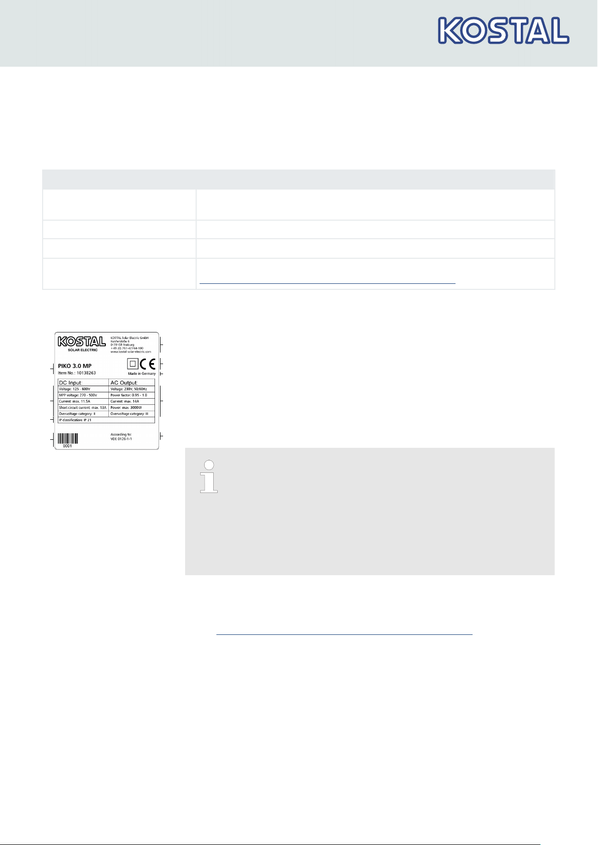
2.2 Identification
Feature Description
Types PIKO 1.5 MP, PIKO 2.0 MP, PIKO 2.5 MP, PIKO 3.0 MP, PIKO 3.6 MP,
PIKO 4.2 MP
Version status of the manual 11/2017
Manufacturer's address
See
Ä Chapter 11 „Contact“ on page 76
Certificates For the certificates, refer to our website under
www.kostal-solar-electric.com/Download/Zertifikate
Rating plate
Bar code for internal use
①
Protection class
②
Technical data of the DC input
③
Article number and product designation
④
Manufacturer's address
⑤
Cover the
⑥
Country of manufacture
⑦
Technical data of the AC output
⑧
Standard for grid monitoring
⑨
Protection class II
–
For Australia only: Cover the Protection class IIsymbol on
and CE mark
the type plate, as described on Ä „ For Australia only:
Cover the Protection class II symbol on the type
plate. “ on page 32.
–
For the serial number, see Ä Chapter 2.5.3 „Designa‐
tions“ on page 9
–
For the position of the type plate, see Ä Chapter 3.1
„Housing“ on page 11.
EU Declaration of Confor‐
mity/Certificates
11/2017 | DOC01664604 | KOSTAL operating instructions PIKO inverter 1.5 - 4.2 MP
The products described in this document comply with the applicable Euro‐
pean Directives. For the certificates for the products, refer to our website
under
www.kostal-solar-electric.com/Download/Zertifikate
7
General information
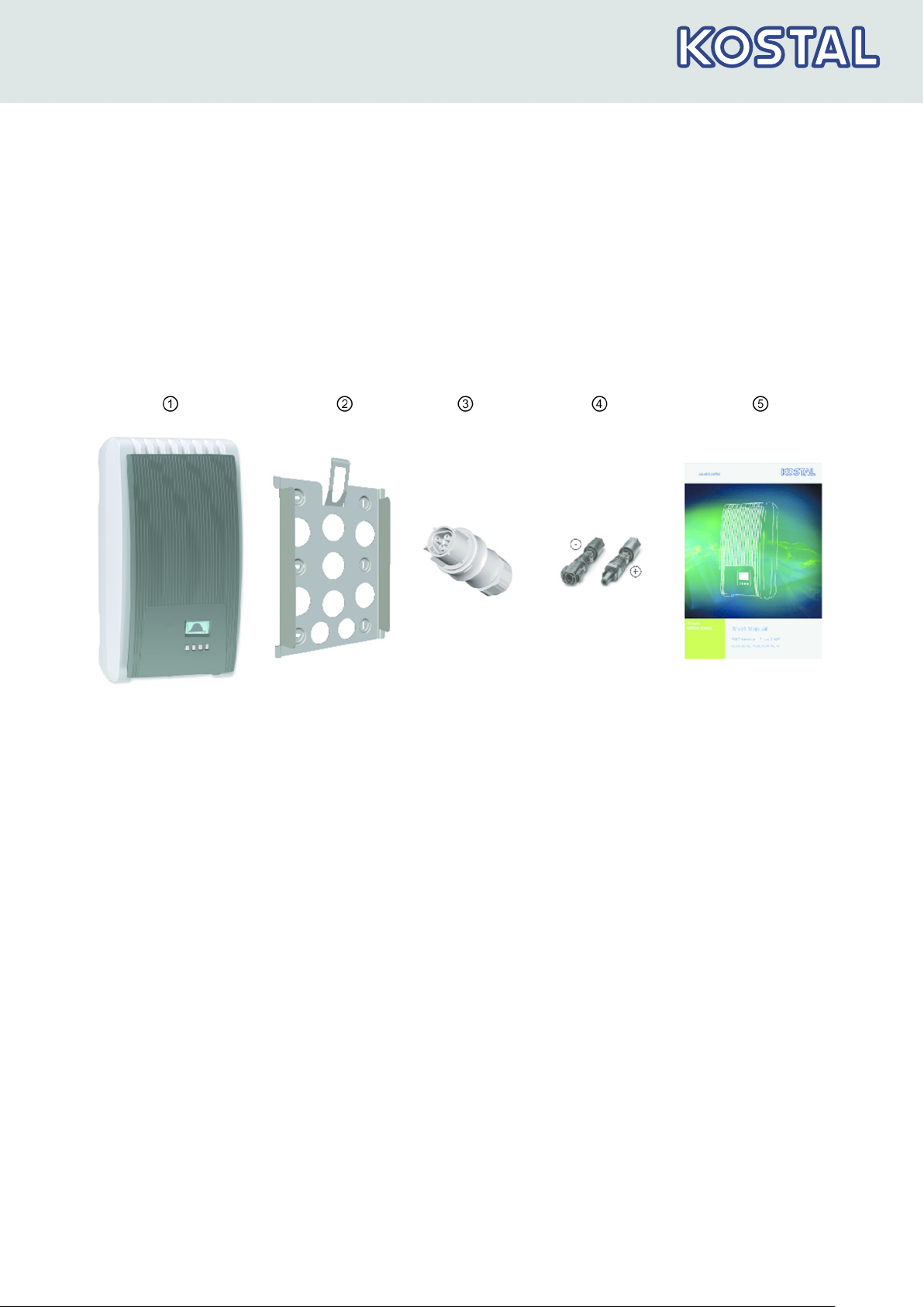
2.3 Scope of delivery
n Inverter ①
n Mounting plate ②
n AC plug ③
n 1 pair SUNCLIX plug-in connectors ④
n Short Manual ⑤
Fig. 1: Scope of delivery
2.4 Intended use
n
n PV generator must be used that have an IEC 61730 class A rating
n If the maximum AC operating voltage is higher than the maximum
The inverter must only be used in grid-coupled photovoltaic systems.
The inverter is suitable for all PV generator with connections that do not
need to be grounded.
because the inverter does not have electrical isolation.
system voltage of the PV generator, then PV generators must be used
that have a maximum system voltage that is higher than the AC grid
voltage.
11/2017 | DOC01664604 | KOSTAL operating instructions PIKO inverter 1.5 - 4.2 MP
8
General information
2.5 About this manual
2.5.1 Contents
This manual describes the inverters of the types PIKO 1.5 - 4.2 MP. The
points at which the types dier are marked in the text.
This manual contains all information that a specialist needs to set up and
operate the inverters. Follow the instructions of the respective manufac‐
turers when installing other components (e.g. PV generator, cables).
2.5.2 Target group
Unless otherwise indicated, the target audiences of this manual are tech‐
nical professionals and system operators. Technical professionals are, for
example:
2.5.3 Designations
Symbols
n Persons who have the knowledge of terminology and the skills neces‐
sary for setting up and operating photovoltaic systems.
n Persons who have the necessary training, knowledge and experience,
and knowledge of the applicable regulations in order to evaluate and
recognise the dangers inherent in the following work:
– Installation of electrical equipment
– Production and connection of data communication cables
– Production and connection of mains grid power supply cables
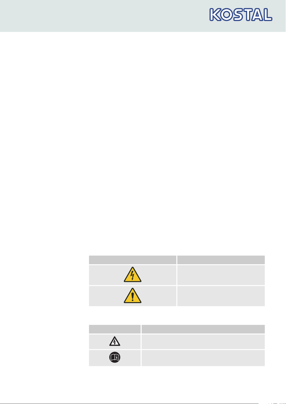
The following table contains the symbols used in this manual.
Warning signs
Type of danger
Warning – high-voltage.
Warning – danger zone.
Symbols used on the
device
11/2017 | DOC01664604 | KOSTAL operating instructions PIKO inverter 1.5 - 4.2 MP
Tab. 1: The following table contains the symbols used on the device.
Cover the Description
Danger from electricity.
Read the manual before using the product.
9
General information
Cover the Description
Bar code with serial number.
Signal words
Keywords used in conjunction with the symbols described:
Signal word Meaning
DANGER! This combination of symbol and
signal word indicates an immediate
dangerous situation that will result
in death or serious injury if it is not
avoided.
NOTICE! This combination of symbol and
signal word indicates a possible
dangerous situation that can result
in material and environmental
damage if it is not avoided.
Abbreviations
Abbreviation Description
Derating Power reduction
DHCP DHCP automatically integrates the device in an existing network (acronym:
Dynamic Host Configuration Protocol)
MSD Internal grid monitoring of the inverter (English: Mains monitoring with allo‐
cated Switching Devices).
MPP Working point producing the most power (English: maximum power point)
MPP tracker Controls the power of the connected module strings to match the MPP
SELV, TBTS, MBTS Schutzkleinspannung (EN: Safety Extra Low Voltage; FR: Très Basse
Tension de Sécurité; ES: Muy Baja Tensión de Seguridad)
V
PV
The PV generator voltage present at the DC connection (photovoltaic
voltage)
11/2017 | DOC01664604 | KOSTAL operating instructions PIKO inverter 1.5 - 4.2 MP
10
11
2
3
14
16
8 7 15
11
10
9
Structure and function
3 Structure and function
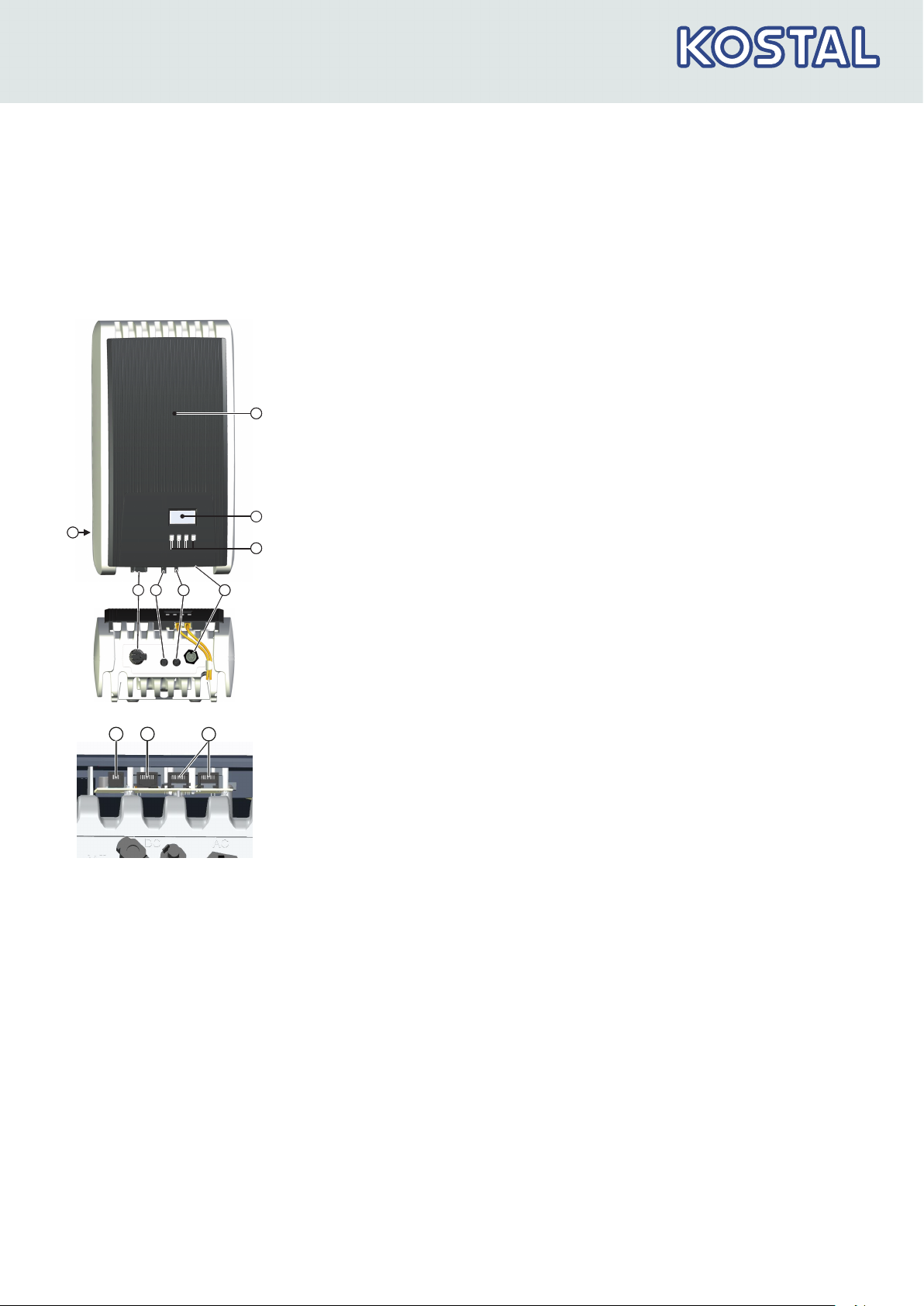
3.1 Housing
Hood
①
Display (monochrome, 128 x 64 pixels)
②
Rating plate, serial number, warnings
③
④
Operating buttons: ESC, r, s, SET (from left to right)
1x AC connection
⑤
1x DC connection Minus(−) for PV generator (Phoenix Contact SUN‐
⑥
CLIX, touch protection)
1x DC connection Plus(+) for PV generator (Phoenix Contact SUNCLIX,
⑦
touch protection)
DC load-break switch (disconnects plus and minus input simultane‐
⑧
ously)
2 x RJ45 sockets (RS485 bus)
⑨
1 x RJ45 socket (TCP/IP Ethernet) for connection to an IP grid via LAN
⑩
1 x RJ10 socket (Modbus RTU) for connection of an energy meter
⑪
The housing components are described in detail below.
11/2017 | DOC01664604 | KOSTAL operating instructions PIKO inverter 1.5 - 4.2 MP
11
Structure and function
3.2 Operating buttons
Button Action
ESC
r
s
SET
Press briefly Goes to the next higher menu
Press longer
(≥ 1 second)
Press briefly
Press briefly
Press briefly Goes to the next lower menu
The operating buttons ④ in
following functions:
General information Guided operation
level
Goes to the status display Jumps to the start of the guided
n Moves the marking bar or the display content upward
n In a numeric setting, moves the marking 1 position to the left
n Increases an adjustment value by 1 increment
n Moves the marking bar or the display content downward
n In a numeric setting, moves the marking 1 position to the left
n Increases an adjustment value by 1 increment
level
Ä Chapter 3.1 „Housing“ on page 11
Function
Navigates 1 step back
Discards any changes
configuration process
—
have the
Press longer
(≥ 1 second)
3.3 Display
3.3.1 General information
For the presentation on the display ② in
„Housing“ on page 11
n
n Errors are indicated by a red flashing backlighting. An event message is
n a selected numerical value starts flashing and can be changed
n Applies a change
n Changes the status of a control element (check box/option box)
Answers a query dialog with
Yes
Goes 1 step back
Ä Chapter 3.1
, the following applies in general:
Symbol : While the inverter is processing large volumes of data, it
cannot process any user inputs. The resulting waiting time is indicated
by the animated sun symbol.
also displayed at the same time.
11/2017 | DOC01664604 | KOSTAL operating instructions PIKO inverter 1.5 - 4.2 MP
12
3
4
2
2
7 8
9
5 6
1
F
Structure and function
3.3.2 Information
The display reacts slower at very low temperatures.
The information shown on the display is described below using illustrative
examples.
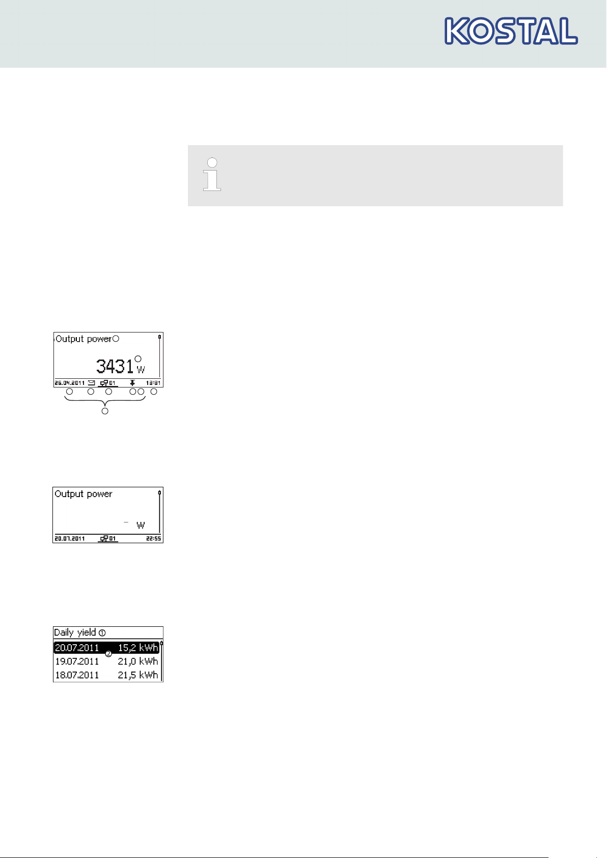
Status display
Numeric yield (day,
month, year)
The status display shows the following values:
Measurement name
①
Measurement with units
②
Date is displayed alternatingly with IP address
③
Cover the
④
Ä Chapter 7 „Event messages“ on page 55
Animated symbol
⑤
Non-confirmed event messages
Connect
symbol with 2‑digit inverter address; indi‐
; for more information, see
.
cates data trac on the RS485 bus.
Cover the
⑥
Cover the
⑦
Time
⑧
IP address of the device when a network connection has been estab‐
⑨
Power reduction
(Derating)
Fixed voltage mode activated
lished, display alternates with ③ – ⑦
The following applies to the status display:
n The measurements shown in the status display are defined under
Settings ▶ Meas. values. Some measurements are always dis‐
played (default setting).
n Current values are not displayed at night (solar irradiation too low;
example in Fig. left).
Daily, monthly and annual yields can be displayed numerically in a list.
Yield period (day/month/year)
①
Individual yields with period and value (1 per row)
②
The yield periods contain the following numbers of individual entries:
n Day yield: last 31 days
n Monthly yield: last 13 months
n Annual yield: last 30 years
1)
A yield value of 0 is shown when the inverter was not yet installed at that
1)
1)
1)
time.
11/2017 | DOC01664604 | KOSTAL operating instructions PIKO inverter 1.5 - 4.2 MP
13
Structure and function
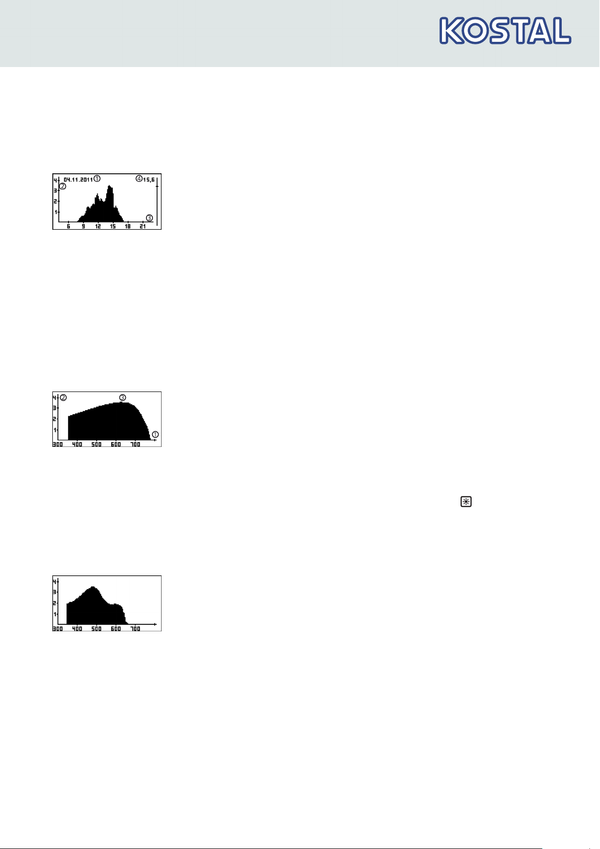
Graphical yield (day,
month, year)
Event messages
PV generator character‐
istic curve
Daily, monthly and annual yields can be displayed graphically in a chart.
Period on an individual yield (here: day yield)
①
②
Y axis 1) 2)
X axis: Time in hours/days/months/years
③
Total of all individual yields shown in the diagram, in kWh
④
3)
The graphical representation can show annual yields for the last 20 years.
1)
Yield in kWh
2)
With addition of
3)
The scaling changes depending on the maximum value.
„M“
: : yield in MWh
Ä Chapter 7 „Event messages“ on page 55
X axis: input voltage in V
①
Y axis: power in kW
②
Peak = MPP
③
If the
„Ch. Curve“
menu item is called, the inverter records the PV gener‐
ator characteristic curve and then displays it (Fig. upper left).
The following applies:
n The inverter traverses the input voltage range and records the power
generated over this range. Duration: a few seconds; is displayed.
n The MPP is at the peak of the PV generator characteristic curve.
n This peak and the PV generator characteristic curve change with the
level of solar irradiation.
n Multiple peaks are a sign of partial shadowing (Fig. left).
n If the top of the curve is flat, the inverter can possibly no longer feed
power into the grid.
11/2017 | DOC01664604 | KOSTAL operating instructions PIKO inverter 1.5 - 4.2 MP
14
Structure and function
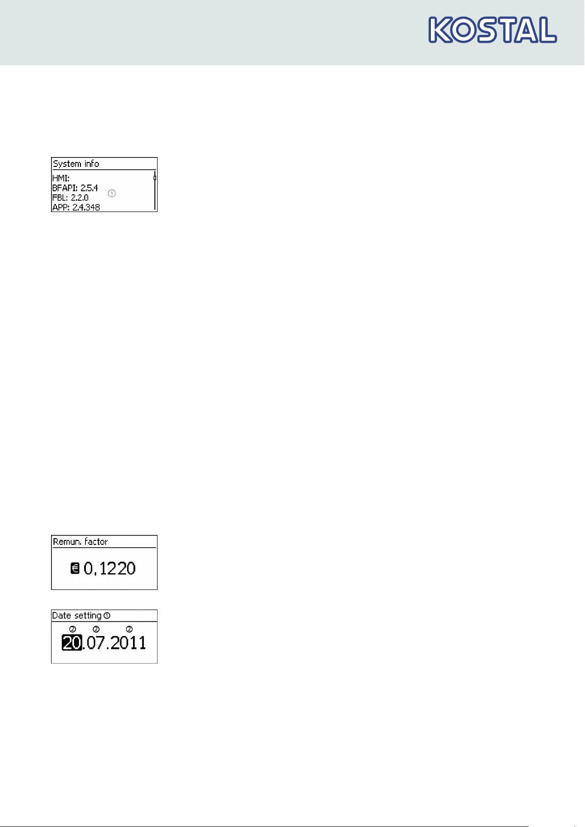
Information
The menu item Information contains the following sub-menu items.
n Contact info
n System info: (see Fig. left)
– Product designation
– Serial number of the inverter
– Information concerning the software and hardware version of the
inverter (see sample ① in Fig. left)
– Inverter address
– Version of the manual that belongs with the inverter
n Reactive power characteristic curve: Diagram of the reactive
power characteristic curve (only if prescribed for the set country)
n Network: Network parameters, partially configurable under Settings
▶ Network
– Host name: Unique name in the network
– DHCP status: DHCP on/o
– Link status: Status of the network connection
– IP address: IP address of the inverter
– Subnet mask: Subnet mask of the inverter
– Gateway: IP address of the network gateway
– DNS address: IP address of the DNS server
– MAC address: Hardware address of the inverter
n Results of the last self-test (only if in the country setting
Italy
is set)
3.3.3 Settings
Numerical settings
When performing numerical settings of remuneration and dates, the fol‐
lowing applies:
Remuneration
n
Possible currencies: £ (Pounds), € (Euros), kr (Krones),
none.
n The maximum value that can be set for remuneration is limited for tech‐
nical reasons. The remuneration must be set using dierent units as
none
required. Example: Dollars instead of Cents (set currency to
Designation of the numerical setting
①
Value to be set; the selected value to be set is highlighted in black.
②
).
Date
When setting the month/year, a check is performed to ensure that the
selected day is valid. If not, then the day is automatically corrected.
Example: 31.02.2011 is corrected to 28.02.2011.
11/2017 | DOC01664604 | KOSTAL operating instructions PIKO inverter 1.5 - 4.2 MP
15
Structure and function
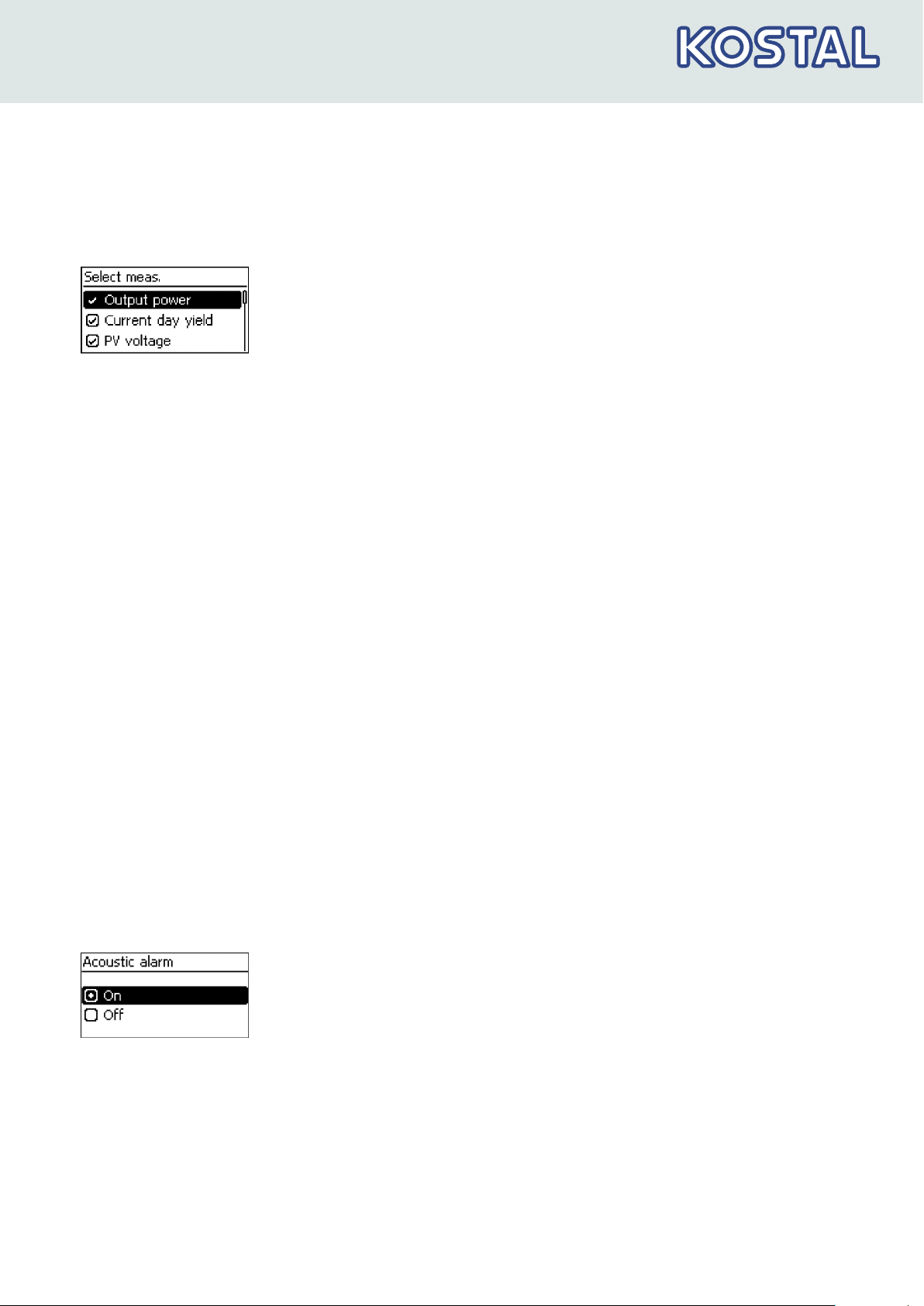
Selection of the measure‐
ments
Selection of the measurements to be shown in the status display. The fol‐
lowing measurements can be selected:
n Output power: Inverter output power
1)
n Current day yield: Day yield since 0:00
n PV voltage: The voltage supplied by the PV generators
n PV current: The current supplied by the PV generators
n Grid voltage: Voltage at the inverter connection
1)
n Grid current: The current fed into the mains grid
n Grid frequency: The frequency of the public grid
n Internal temperature: Internal temperature of the inverter
n Derating Reason for derating
2)
n Max. daily power: The maximum power supplied in the current
3)
day
n Abs. max. power: The maximum power ever fed into the grid
n Max. daily yield: The maximum daily yield achieved
3)
3)
n Operating hours: The operating hours during which the device has
been connected to the grid (including night-time hours).
n Total yield: Yield since commissioning
n CO2 savings: CO2 savings achieved since commissioning
1)
Measurement is always displayed (cannot be switched o)
2)
Possible causes:
– Internal temperature too high
– User default
Power limiter
– Frequency too high
– Controlled by grid operator (feed-in management)
– Delayed increase in power after starting
3)
Can be reset to 0 via Settings ▶ Reset max. vals.
Acoustic alarm
An acoustic alarm sounds (approx. 4.5 kHz) when an event message is
displayed.
n
2 Sounds: Warning
n 3 Sounds: Error
The acoustic alarm is switched o with the factory default settings.
11/2017 | DOC01664604 | KOSTAL operating instructions PIKO inverter 1.5 - 4.2 MP
16

Structure and function
Backlight
TCP/IP network
n off
n automatic: Switches on for 30 seconds when a button is pushed
n Grid feed: (factory setting)
Not feeding
–
: Switches on for 30 seconds when a button is pushed;
then switches o
–
Feeding
: Switches on for 30 seconds when a button is pushed; then
dims
–
A prerequisite for this is that you know the parameters
required for setting up the TCP/IP network connection.
Consult (further) technical professionals if required.
–
DHCP is activated in the device ex-works. This allows
automatic integration of the device in most networks.
3.3.4 Service menu
Network settings, required for network communication, e. g. with an
Internet portal:
n DHCP: Switch DHCP on/o
n IP address: IP address of the inverter
n Subnet mask: Subnet mask of the inverter
n Gateway: IP address of the network gateway
n DNS address: IP address of the DNS server
n web-portal: Settings at the web portal
– Web portal setting: Disabling of data transmission and selec‐
tion of a web portal
– Connection check: Checks the internet connection and indicates
the result
The service menu items are described below. Some items are password
protected; see
Ä Further information on page 47
(menu structure)
You can obtain the password from technical support; see
Ä Chapter 11 „Contact“ on page 76
.
NOTICE!
Risk of reduced yields. In the service menu, inverter and grid
parameters can be changed. The service menu must only be
operated by a specialist, who ensures that the change does
not violate applicable regulations and standards!
11/2017 | DOC01664604 | KOSTAL operating instructions PIKO inverter 1.5 - 4.2 MP
17
Structure and function
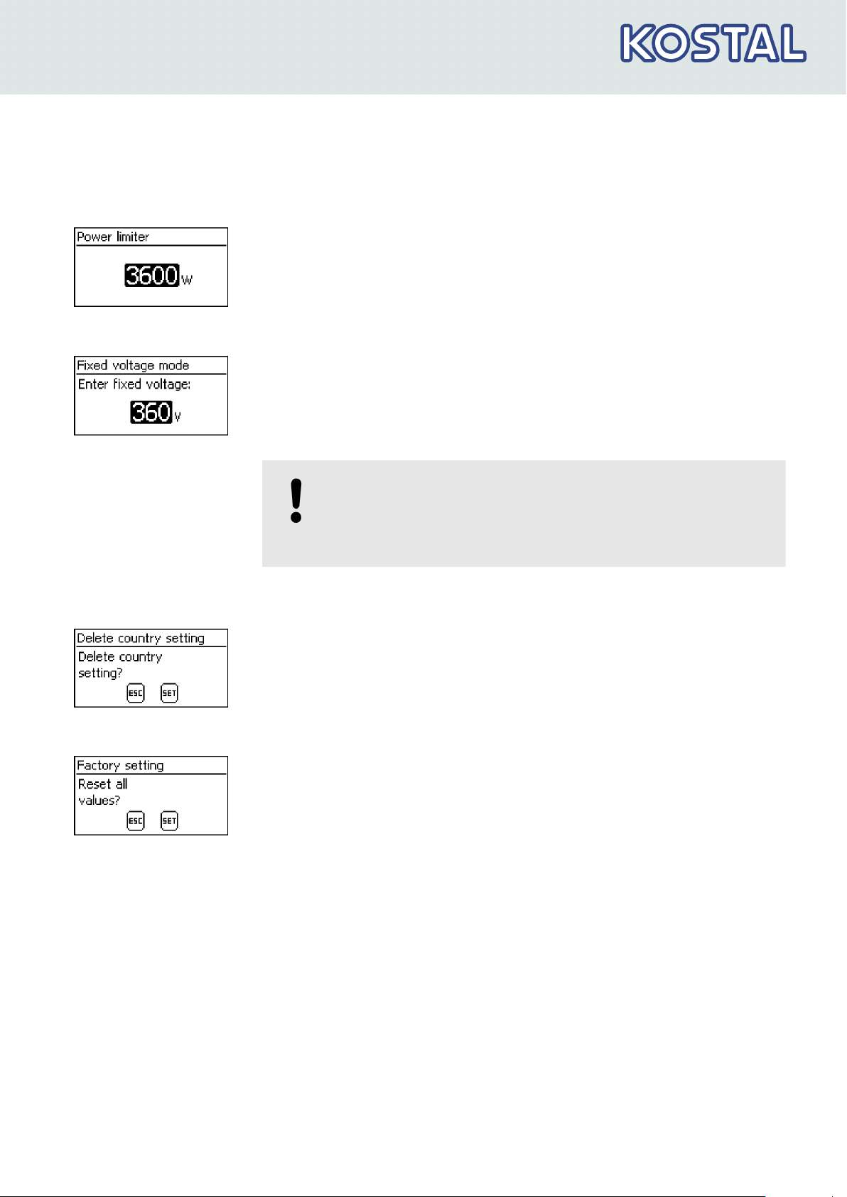
Power limiter
Fixed voltage
The inverter output power can be manually limited to a minimum of 500 W.
When the power is manually limited, the
in the status display and the
„Derating“/„Cause: User default“
Power reduction
symbol is shown
measure‐
ment is displayed.
The device can regulate the input voltage to a manually adjustable value.
This switches o the automatic setting of the MPP (MPP tracking). The
input voltage can be adjusted over a range between the maximum and
minimum input voltage and the minimum input voltage in 1V steps.
Exemplary application: Hydroelectric installation
Delete country setting
Factory setting
NOTICE!
Before setting a fixed input voltage, make sure that the PV
generator is suitable for this. Otherwise, this may result in
yield losses or damage to the system.
After the country setting has been deleted the device restarts anew and
displays the guided 1st commissioning menu.
Resetting the device to the factory setting deletes the following data:
n
Yield data
n Event messages
n Date and time
n Country setting
n Display language
n Network settings
After the factory setting has been deleted, the device restarts anew and
displays the guided 1st commissioning menu.
11/2017 | DOC01664604 | KOSTAL operating instructions PIKO inverter 1.5 - 4.2 MP
18
Structure and function
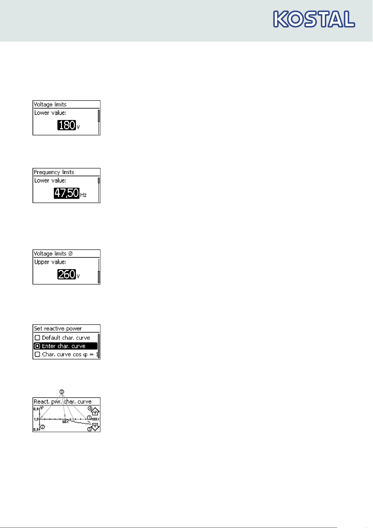
Voltage limits (peak value)
Frequency limits
The following voltage limits can be changed:
n Upper disconnection value
1)
n Lower disconnection value1) (Fig. left)
1)
The disconnection value relates to the peak value of the voltage.
The following frequency limits can be changed:
n Upper disconnection value
n Lower disconnection value (Fig. left)
n Derating switch-on threshold (because frequency is too high)
n Frequency threshold when switching on again
Voltage limits ø (average
value)
Reactive power charac‐
teristic curve
The following voltage limits can be changed:
n Upper disconnection value1) (Fig. left)
n Lower disconnection value
1)
The disconnection value relates to the average value of the voltage.
1)
Overview:
The reactive power characteristic curve must be set during 1st commis‐
sioning if this is prescribed for the previously selected country. The fol‐
lowing applies:
n
3 characteristic curves are available for selection (Fig. left):
– Default. char. curve (pre-defined)
– Enter char. curve (manually adjustable)
– Char. curve cos φ = 1 (pre-defined)
n After configuration, the characteristic curve is displayed as a graph
(example in Fig. left).
① x-axis, output power P in %
② y-axis, phase shift cos φ
③ Nodes (in example: 4 nodes)
④ Arrow symbol
⑤ Arrow symbol
Overexcitation
Underexcitation
Technical details
11/2017 | DOC01664604 | KOSTAL operating instructions PIKO inverter 1.5 - 4.2 MP
19
Structure and function
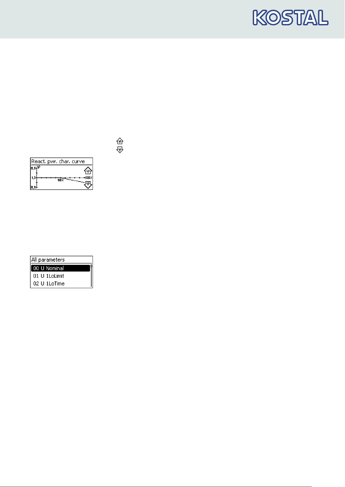
n Each characteristic curve is defined by 2 to 8 nodes.
n A node is defined by the output power P of the inverter (x-axis) and the
associated phase shift (y-axis).
n The phase shift can be set over a range of 0.95 (overexcitation) through
1.00 (no phase shift) to 0.95 (underexcitation).
n The type of phase shift is shown in the graph using arrow symbols
defined as follows (defined from the point of view of the inverter):
Overexcitation, inductive
Underexcitation, capacitive
n The 3 characteristic curves available for selection have the following
properties:
Default char. curve: pre-defined according to the selected
country (example in Fig. left).
Char. curve φ = 1: pre-defined with cos φ = constantly 1.00. This
characteristic curve must be selected if no reactive power control is to
be performed on the device.
Enter char. curve: The number of nodes and their x/y values can
be configured. Exceptions: The first node is always at x (P %) = 0 %,
the last always at x (P %) = 100 %.
All parameters
Service technicians can use this menu item for changing additional MSD
parameters.
3.4 Cooling
The internal temperature control system prevents excessive operating tem‐
peratures. When the internal temperature is too high, the inverter adjusts
the power consumption from the PV generators to reduce the heat dissipa‐
tion and operating temperature.
The inverter is convection cooled via fins on the front and rear side. A
maintenance-free fan circulates the heat within the closed housing evenly
over the entire surface of the housing.
3.5 Grid monitoring
The inverter constantly monitors the mains grid parameters while feeding
the grid. If the grid deviates from the legally prescribed specifications then
the inverter automatically switches o. When the grid conforms to the
legally prescribed specifications then the inverter automatically switches
on again.
11/2017 | DOC01664604 | KOSTAL operating instructions PIKO inverter 1.5 - 4.2 MP
20

Structure and function
3.6 Data communication
The device has the following communication interfaces:
n 1x RJ45 socket (Ethernet for TCP/IP grid) for communication, e.g. for
connection to the PIKO Solar Portal via your network.
n 2x RJ45 sockets (RS485 bus) for communication with external devices,
e.g. a data logger
n 1x RJ10 socket (Modbus RTU) for communication e. g. with an external
energy counter
3.6.1 Data
The inverter can transmit a wide range of data to other devices. Some of
this data is shown on the display and certain data is stored in the internal
memory (EEPROM) as described below.
Displayed data
Logged data (EEPROM)
n Voltage and current of the PV generator
n Power and current fed into the grid
n Voltage and frequency of the power grid
n Energy yields on a daily, monthly and annual basis
n Error conditions, notes
n Version information
n Event messages with date
n Energy yields on a daily, monthly and annual basis
The storage resolution of the energy yield data is as follows:
Energy yield data
10-minute values 31 days
Daily values 13 months
Monthly values 30 years
Annual values 30 years
Total yield permanent
Storage resolution/period
3.6.2 Network (TCP/IP)
Using the TCP/IP interface, the device can transmit yield data and event
messages to the PIKO Solar Portal
of-charge Solar Portal, the yield data can be displayed graphically.
11/2017 | DOC01664604 | KOSTAL operating instructions PIKO inverter 1.5 - 4.2 MP
www.piko-solar-portal.com
. In the free-
21
Structure and function
n Before you can use the Solar Portal, the inverter must send its data to
the PIKO Solar Portal. Once the 1st commissioning communication
between the inverter and the Solar Portal has been established, the
user can carry out the registration process and then add the inverter to
the user's system.
n The local network settings must be set at the inverter in order to estab‐
lish a connection to the Internet portal server. This can be performed
automatically or manually:
Automatically: If IP addresses are automatically assigned in your net‐
work (DHCP), then no settings need to be made at the inverter.
Manually: If IP addresses are not automatically assigned in your net‐
work, then you must manually set the inverter network settings via
Settings ▶ Network; see
Ä „TCP/IP network“ on page 17
n The address of the PIKO Solar Portal is permanently stored in the
inverter and cannot be changed.
n Once the network connection is established, the inverter automatically
starts non-encrypted transmission of data to the server.
The network cable must be disconnected in order to prevent
transmission of the data, or data transmission must be dis‐
abled according to Ä „TCP/IP network“ on page 17.
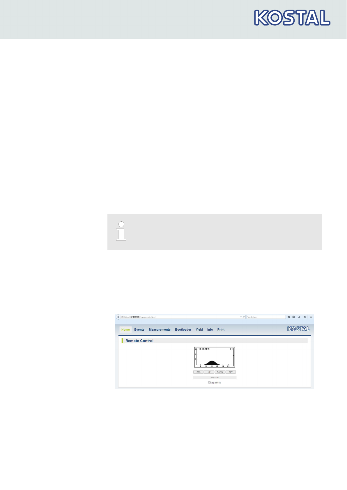
Furthermore, you can use the inverter interface to display yield data and
other information as HTML pages via the internal web server. You need a
PC connection to indicate the data. The web server can be called up via a
browser (e.g. Mozilla Firefox or Internet Explorer). To enable the connec‐
tion, enter the IP address of the inverter (see inverter status indication) in
the input line of the browser (e.g. http://192.168.103.168). To enable the
connection, enter the IP address of the inverter (see inverter status indica‐
tion) in the browser.
Fig. 2: Example 1 of an HTML page
11/2017 | DOC01664604 | KOSTAL operating instructions PIKO inverter 1.5 - 4.2 MP
22
Structure and function
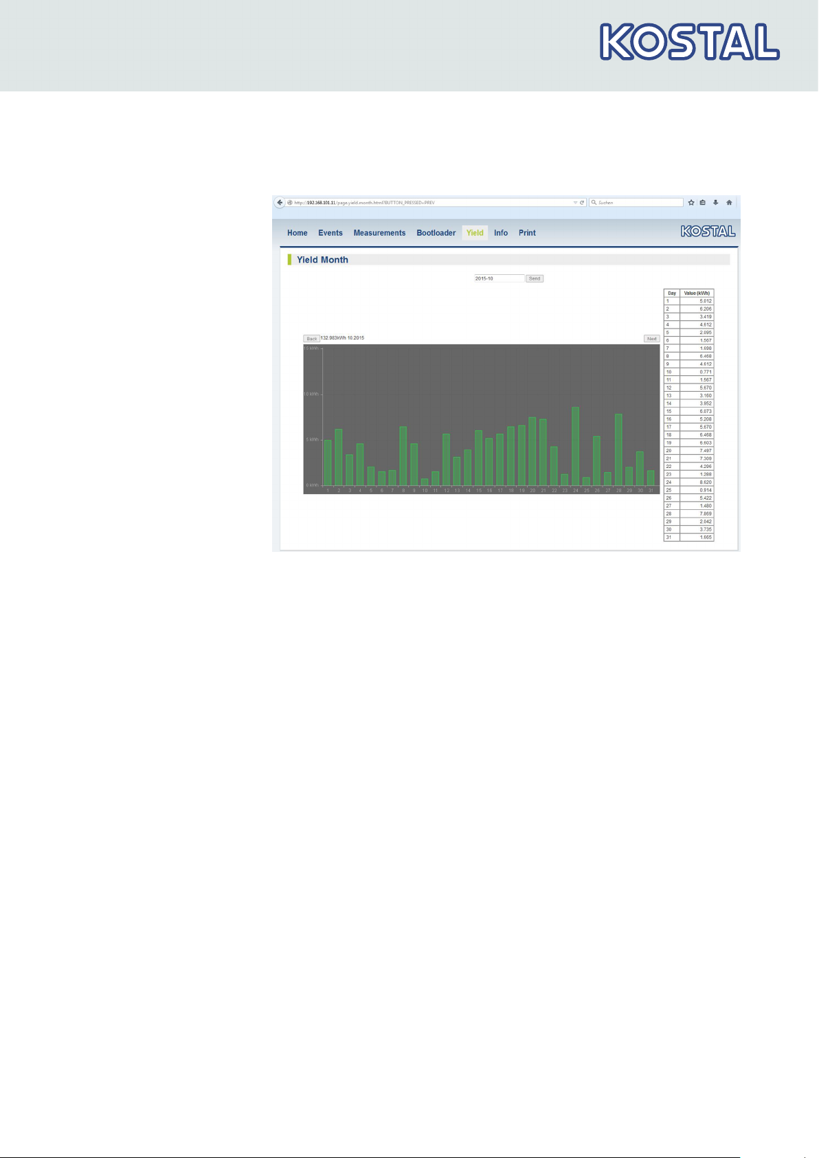
3.6.3 RS485 bus
Fig. 3: Example 2 of an HTML page
The inverter communicates with other devices via an RS485 bus. The fol‐
lowing applies:
The following applies:
n The inverter has two RS485 interfaces (RJ45 sockets) on the lower side
of the casing.
n The beginning and end of the RS485 bus must be terminated; see
Ä Chapter 3.6.5 „RS485 termination“ on page 27
.
n Standard RJ45 cables can be used as bus cables (Cat-5 patch cables,
not supplied). Use an alternative data connection cable for longer con‐
nections; see
cable“ on page 26
n The inverters connected to the RS485 bus operate as
Ä Chapter 3.6.4 „Alternative RS485 data connection
.
slaves.
11/2017 | DOC01664604 | KOSTAL operating instructions PIKO inverter 1.5 - 4.2 MP
23

Structure and function
The following inverters have compatible data interfaces and
can be connected to the RS485 bus as slaves:
–
PIKO 1.5 MP
–
PIKO 2.0 MP
–
PIKO 2.5 MP
–
PIKO 3.0 MP
–
PIKO 3.6 MP
–
PIKO 4.2 MP
Comply with the instructions in the manuals of these
devices relative to addressing, termination, and approved
data cables.
If in the country setting Italy is set, then the RS485 bus must
be connected as follows to enable control through an
external device in accordance with CEI 0-21.
–
External fast switch-o (Italian: Teledistacco): If the
lines 31) and 81) of the RS485 bus2) are connected, e. g.
via an external relay, the following applies:
Relay closes: The inverters on the bus disconnect them‐
selves from the network.
Relay opens: The inverters connected on the network
connect themselves to the network (regular operation).
–
Switch-over of the grid frequency disconnection thresh‐
olds (Ital.: Modalità definitiva di funzionamento del sis‐
tema di protezione di interfaccia (impiego del SPI sulla
base di letture locali e di informazioni/comandi esterni)):
If the lines 51) and 81) of the RS485 bus2) are connected,
e. g. via an external relay, the following applies:
Relay closes: The inverters connected on the bus set the
switch-o thresholds in accordance with CEI 0-21 to
47.5 Hz and 51.5 Hz.
Relay opens: The inverters connected on the bus set the
switch-o thresholds in accordance with the country set‐
ting Italy ; Ä Chapter 9 „Technical data“ on page 63
We recommend that you integrate the wiring of lines 3, 5,
and 8 in the bus termination.
1)
Contact assignment of the RJ45 plug for the RS485 bus:
Fig. 4.
2)
See Ä Chapter 3.1 „Housing“ on page 11 ⑥ and ⑦.
11/2017 | DOC01664604 | KOSTAL operating instructions PIKO inverter 1.5 - 4.2 MP
24
 Loading...