

Kostal PIKO 4.2, PIKO 3.0, PIKO 7.0, PIKO 5.5, PIKO 4.6 Operating Manual
...
Homepage_Cover
Operating manual
PIKO inverter
3.0 - 20

Legal notice
23456789101112
1
KOSTAL Solar Electric GmbH
Hanferstraße 6
79108 Freiburg i. Br.
Germany
Phone +49 (0)761 477 44 - 100
Fax +49 (0)761 477 44 - 111
www.kostal-solar-electric.com
Exclusion of liability
All names, trademarks, product names or other designations used in this manual may be legally protected even
if not indicated as such (e.g. as a trademark). KOSTAL
Solar Electric GmbH assumes no liability or warranty for
their free usage. The illustrations and texts have been
compiled with great care. However, the possibility of
errors cannot be ruled out. The compilation is made
without any guarantee.
General note on gender equality
KOSTAL Solar Electric GmbH is aware of the importance of language with regard to the equality of women
and men and always makes an eort to reflect this in
the documentation. Nevertheless, for the sake of readability we are unable to use non-gender-specific terms
throughout and use the masculine form instead.
© 2016 KOSTAL Solar Electric GmbH
All rights reserved by KOSTAL Solar Electric GmbH,
including those of reproduction by photocopy and storage in electronic media. Commercial use or distribution
of the texts, displayed models, diagrams and photographs appearing in this product is not permitted. This
manual may not be reproduced, stored, transmitted or
translated in any form or by means of any medium, in
whole or in part, without prior written permission.
Software version as of FW: 05.41
User Interface (UI) as of: 06.20
06 / 2016 | DOC01728451 | KOSTAL operating manual PIKO inverter 3.0 - 20
2

Contents
23456789101112
1
1. General information 6
1.1 Proper use ................................................................................................................................. 8
1.2 EU declarations of conformity ................................................................................................... 10
1.3 About this manual .................................................................................................................... 11
1.4 Notes in this manual ................................................................................................................. 13
1.5 Symbols used .......................................................................................................................... 17
1.6 Labels on the inverter ............................................................................................................... 18
2. Device and system description 19
2.1 The photovoltaic system ........................................................................................................... 20
2.2 Inverter components ................................................................................................................ 22
2.3 Inverter functions ..................................................................................................................... 38
3. Installation 40
3.1 Transport and storage .............................................................................................................. 41
3.2 Scope of delivery ...................................................................................................................... 42
3.3 Installation ................................................................................................................................ 44
3.4 Electrical connection ................................................................................................................ 47
3.5 Connection of solar module ...................................................................................................... 50
3.6 Connection of communication components ............................................................................. 55
3.7 Initial commissioning ................................................................................................................ 59
4. Operation and operating the device 62
4.1 Switching on the inverter .......................................................................................................... 63
4.2 Switching o the inverter .......................................................................................................... 64
4.3 De-energising the inverter ......................................................................................................... 65
4.4 Control panel ............................................................................................................................ 66
4.5 Operational status (display) ....................................................................................................... 69
4.6 Operational status (LEDs) ......................................................................................................... 70
4.7 The menu structure of the inverter ............................................................................................ 71
4.8 The service menu ..................................................................................................................... 76
4.9 The energy management system in the inverter ........................................................................ 77
4.10 Event codes ............................................................................................................................. 78
06 / 2016 | DOC01728451 | KOSTAL operating manual PIKO inverter 3.0 - 20
3

5. Web server 86
23456789101112
1
5.1 The web server ........................................................................................................................ 87
5.2 Using the web server ................................................................................................................ 88
5.3 Connecting the inverter and computer ...................................................................................... 89
5.4 Menu structure in web browser ................................................................................................ 91
5.5 Web server main menu ............................................................................................................. 93
5.6 Web server submenus .............................................................................................................. 94
6. System monitoring 105
6.1 Create connection between computer and inverter ................................................................. 106
6.2 The log data ........................................................................................................................... 109
6.3 Retrieve, save and graphically represent log data ................................................................... 112
7. Active power control 115
7.1 Why active power control? ..................................................................................................... 116
7.2 Limitation of the PV feed-in capacity ....................................................................................... 117
7.3 Activate power control with a ripple control receiver ............................................................... 118
7.4 Install the ripple control receiver .............................................................................................. 119
8. Self-consumption 122
8.1 Self-consumption overview .................................................................................................... 123
8.2 Electrical connection for self-consumption .............................................................................. 124
8.3 Set up self-consumption control in the web server ................................................................. 125
9. Maintenance 132
9.1 Maintenance and service ........................................................................................................ 133
9.2 Fan cleaning ........................................................................................................................... 134
9.3 Update software (communication board) ................................................................................ 138
9.4 Update software (inverter firmware) ........................................................................................ 140
9.5 Update software (country settings) ......................................................................................... 141
06 / 2016 | DOC01728451 | KOSTAL operating manual PIKO inverter 3.0 - 20
4

General information
23456789101112
1
10. Technical data 142
10.1 Technical data ........................................................................................................................ 144
10.2 Block diagram ........................................................................................................................ 151
11. Accessories 152
11.1 Installation of PIKO BA Sensor ................................................................................................ 153
11.2 Operating the system with multiple inverters and PIKO BA Sensor .......................................... 157
11.3 Additional accessories ............................................................................................................ 160
12. Appendix 162
12.1 Type plate ............................................................................................................................... 163
12.2 Warranty and service .............................................................................................................. 164
12.3 Handover to the operator ....................................................................................................... 165
12.4 Disassembly and disposal ...................................................................................................... 166
Index 167
06 / 2016 | DOC01728451 | KOSTAL operating manual PIKO inverter 3.0 - 20
5

1
23456789101112
Navibutton Verlinkung Kapitel 01
1. General information
1.1 Proper use .................................................................................................................................. 8
1.2 EU declarations of conformity ................................................................................................... 10
1.3 About this manual ..................................................................................................................... 11
1.4 Notes in this manual ................................................................................................................. 13
1.5 Symbols used ........................................................................................................................... 17
1.6 Labels on the inverter ............................................................................................................... 18
1.
06 / 2016 | DOC01728451 | KOSTAL operating manual PIKO inverter 3.0 - 20
6

General information
23456789101112
1
Thank you for choosing a PIKO inverter from KOSTAL
Solar Electric GmbH! We hope you enjoy consistently
high energy yields with the PIKO inverter and your
photovoltaic system.
If you have any technical questions, please call our
service hotline:
n
Germany and other countries 1
+49 (0)761 477 44 - 222
n
France, Belgium, Luxembourg
+33 16138 4117
n
Greece
+30 2310 477 555
n
Italy
+39 011 97 82 420
n
Spain, Portugal 2
+34 961 824 927
n
Turkey 3
+90 212 803 06 26
1
Language: German, English
2
Language: Spanish, English
3
Language: English, Turkish
06 / 2016 | DOC01728451 | KOSTAL operating manual PIKO inverter 3.0 - 20
7

General information
23456789101112
1
1.1 Proper use
The PIKO inverter converts direct current into alternating
current. This can be used as follows:
n
For self-consumption
n
For feed-in into the public grid
The device may only be used in grid-connected photovoltaic systems within the permissible power range and
under the permissible ambient conditions. The device is
not intended for mobile use.
Inappropriate use can be hazardous and lead to injury
or even death to the user or third parties. Material damage to the device and other equipment can also occur.
The inverter may therefore only be used for its intended
purpose.
All components fitted on the inverter or in the PV system
must satisfy the standards and guidelines that apply in
the country of installation.
06 / 2016 | DOC01728451 | KOSTAL operating manual PIKO inverter 3.0 - 20
8

General information
23456789101112
1
Exclusion of liability
Any use that diers from or goes beyond the stated
intended purpose is considered inappropriate. The
manufacturer accepts no liability for any damage resulting from this. Modifications to the inverter are prohibited.
The inverter may only be used if safe to operate and in
technically perfect condition. Any instance of misuse will
cause the termination of the warranty, guarantee and
general liability of the manufacturer.
Only a qualified electrician may open the device. The
inverter must be installed by a trained electrician (according to DIN VDE 1000-10 or BGV A3 accident prevention
regulations) who is responsible for observing the applicable standards and regulations.
Work that could aect the electrical power system of
the relevant energy supply company at the site of the
solar power feed-in may only be carried out by qualified
electricians expressly authorised (licensed) by the energy
supply company. This includes changes to the factory-preset parameters. The installer must always observe
the regulations of the energy supply company.
IMPORTANT
INFORMATION
The inverter may only be installed,
maintained and repaired by a
trained and qualified electrician.
The electrician is responsible for
ensuring that the applicable standards and regulations are observed
and implemented. Work that could
aect the electrical power system
of the relevant energy supply company at the site of the solar power
feed-in may only be carried out
by qualified electricians expressly
authorised (licensed) by the energy
supply company.
This includes changes to the
factory-preset parameters.
Factory settings may only be changed by qualified electrical installers or persons with at least comparable or
higher technical qualifications, e.g. foremen, technicians
or engineers. When doing so, all requirements are to be
observed.
06 / 2016 | DOC01728451 | KOSTAL operating manual PIKO inverter 3.0 - 20
9

General information
23456789101112
1
1.2 EU declarations of conformity
KOSTAL Solar Electric GmbH hereby declares that the inverter described in this document complies
with the basic requirements and other relevant conditions of the directives listed below.
n
Directive 2014/30/EU
(on the approximation of the laws of the Member States relating to electromagnetic compatibility
(EMC))
n
Directive 2014/35/EU
(on the harmonisation of the laws of the Member States relating to the making available on the
market of electrical equipment designed for use within certain voltage limits – for short:
Low Voltage Directive)
You will find a detailed EU Declaration of Conformity at:
www.kostal-solar-electric.com/Download/Zertifikate
06 / 2016 | DOC01728451 | KOSTAL operating manual PIKO inverter 3.0 - 20
10

General information
23456789101112
1
1.3 About this manual
Read this manual carefully in its entirety.
It contains important information on the installation and
operation of the inverter. Pay particular attention to the
instructions regarding safe usage. KOSTAL Solar Electric
GmbH assumes no liability for damages arising from the
non-observance of this manual.
This manual is an integral part of the product. It applies
exclusively to the PIKO inverters from KOSTAL Solar
Electric GmbH. Keep this manual and give it to the new
owner should you pass it onto a new operator.
The installer and the operator must have unrestricted
access to these instructions at all times. The installer
must be familiar with this manual and follow all
instructions.
The most recent version of the operating manual for
yourproduct is available in the download area at
www.kostal-solar-electric.com.
Target group
TIP
Print both sides on one sheet of
paper when printing out this operating
manual.
This saves paper and the document
remains easy to read.
This manual is intended for trained and qualified electrical
technicians who install, maintain and repair the inverters.
The inverters described in this manual dier from one
another in terms of particular technical details. Information and handling instructions that only apply to certain
device types are to be identified accordingly.
Information concerning your safety or that of the unit is
highlighted especially.
06 / 2016 | DOC01728451 | KOSTAL operating manual PIKO inverter 3.0 - 20
11
General information
23456789101112
1
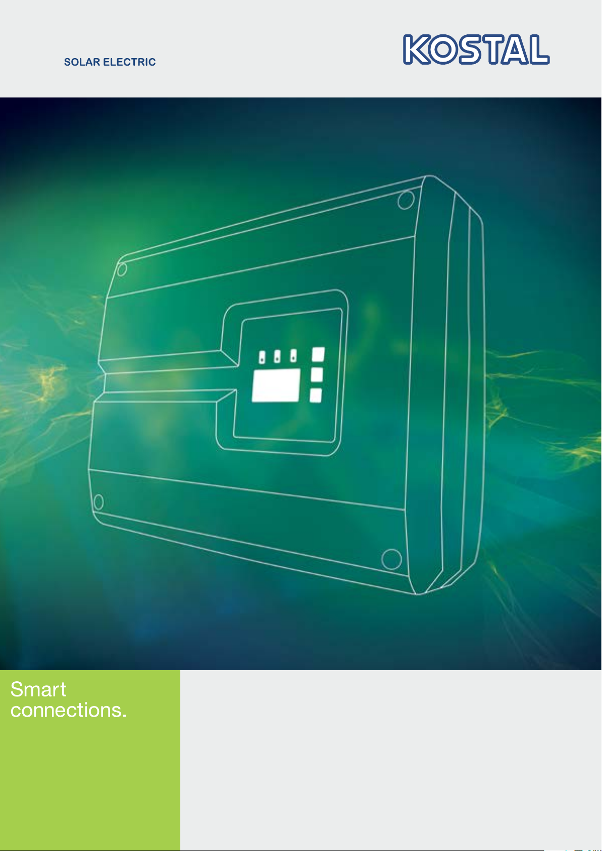
Navigation through the document
In order to enable navigation through this document, it
contains clickable areas.
One of these is the navigation bar in the header of each
page. Here you can go to the overview pages of the
individual chapters in one click.
The table of contents can also be used in this way.
From
the index at the beginning of each chapter you can go to
the indicated sub-chapter in one click.
Fig. 1: Navigation through the document
1
Calling up the main table of contents
2
Navigation bar
3
Tables of contents
You can navigate to the referenced points in the
document within the instruction text using the
cross-references.
Ch. 1
Fig. 1, It. 2
Fig. 2: Examples of cross-references
06 / 2016 | DOC01728451 | KOSTAL operating manual PIKO inverter 3.0 - 20
12
General information
23456789101112
1
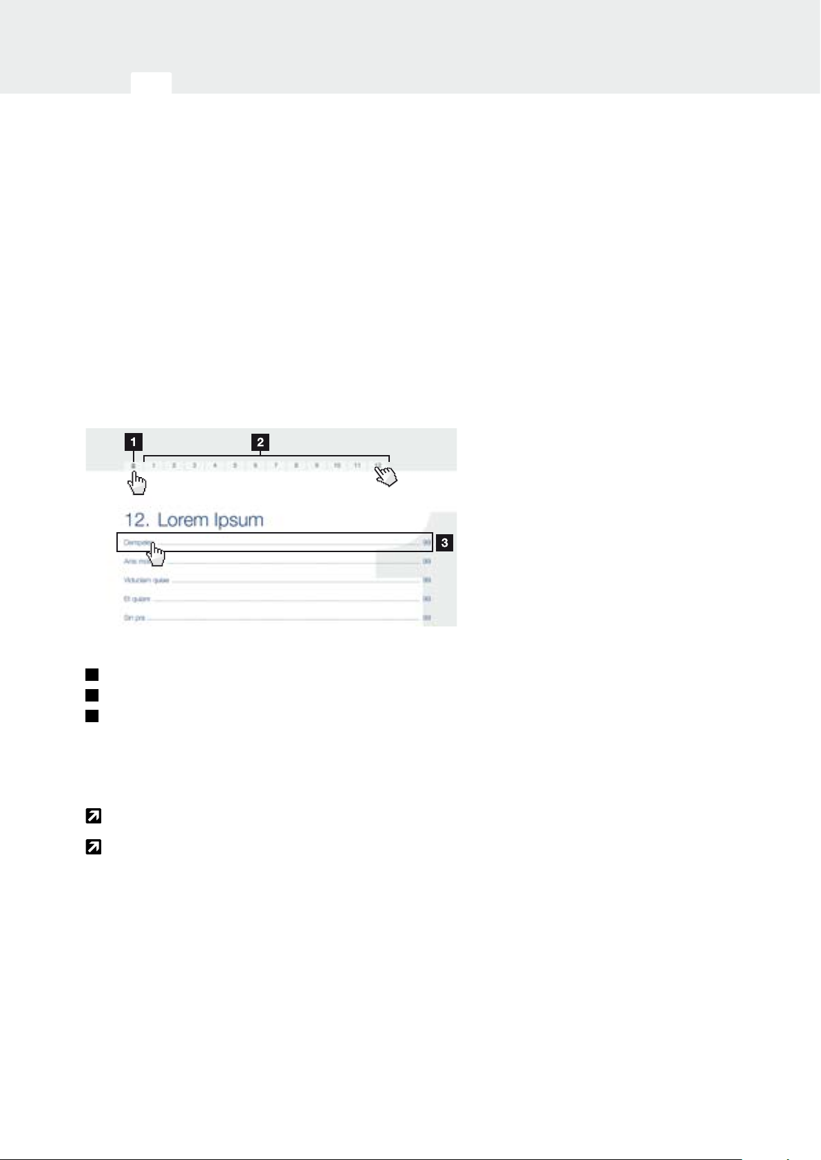
1.4 Notes in this manual
Fig. 3: Safety instructions in this manual
1
Reference icon within the instruction text
2
Warning
3
Information note
4
Other notes
Notes have been incorporated into the instruction text. A
dierentiation is made in this manual between warnings
and information notes. All notes are identified in the text
line with an icon.
06 / 2016 | DOC01728451 | KOSTAL operating manual PIKO inverter 3.0 - 20
13
General information
23456789101112
1
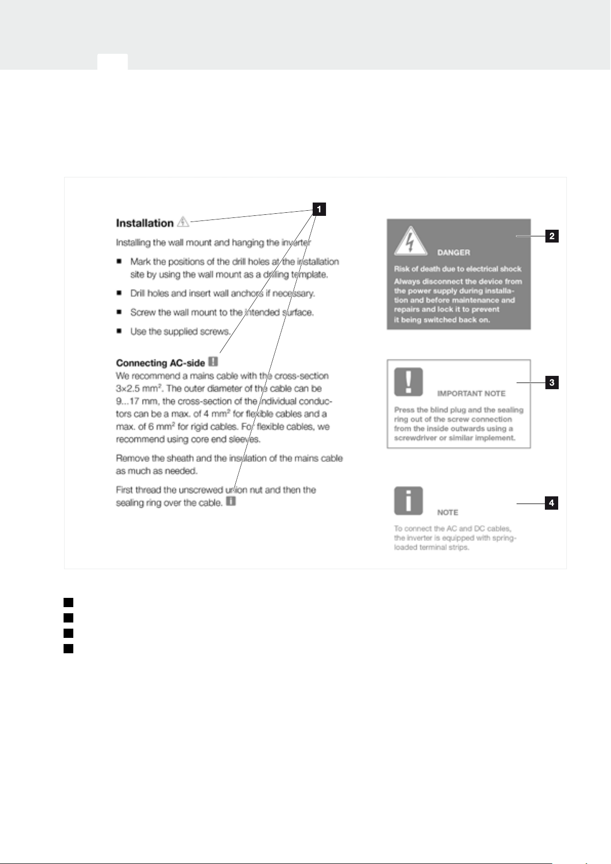
Warnings
The warnings refer to life-threatening dangers. Serious
injuries possibly resulting in death may occur.
Each warning consists of the following elements:
Fig. 4: Structure of the warnings
1
Warning symbol
2
Signal word
3
Type of danger
4
Corrective actions
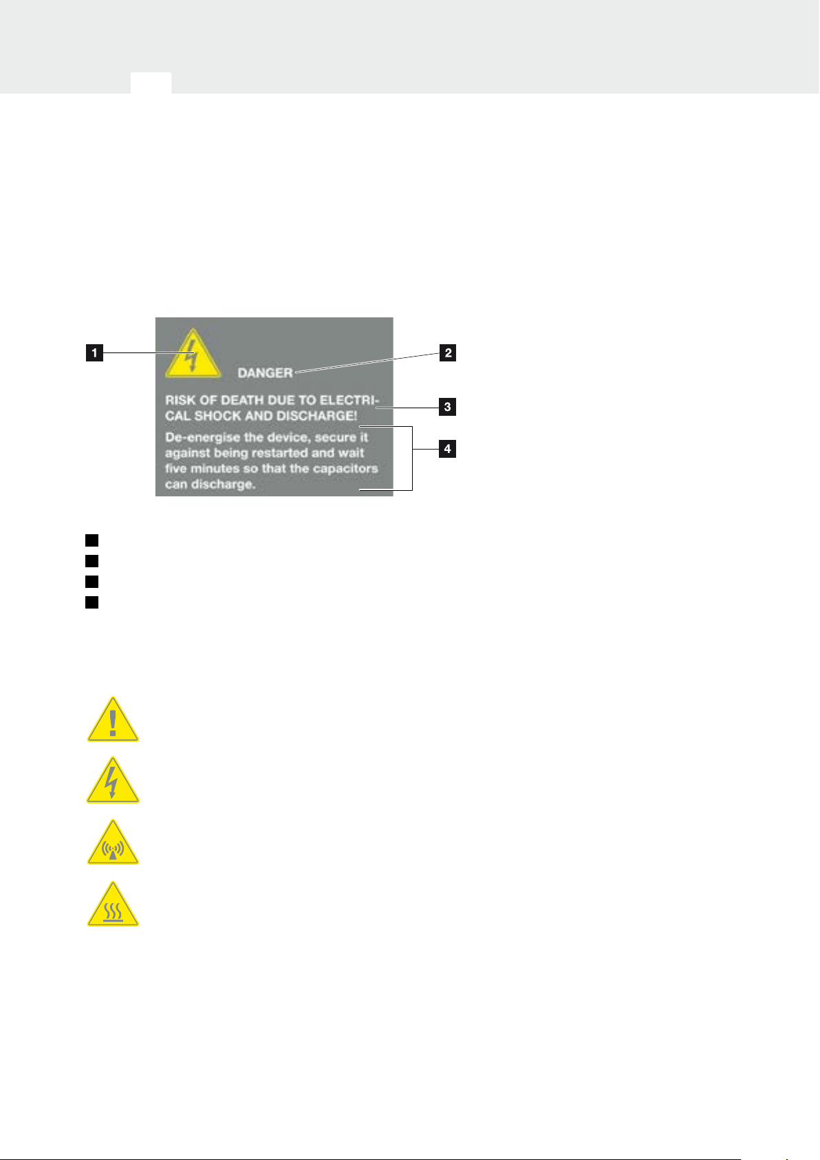
Warning symbols
Danger
Danger due to electrical shock and discharge
Danger due to electromagnetic fields
Danger due to burns
06 / 2016 | DOC01728451 | KOSTAL operating manual PIKO inverter 3.0 - 20
14

General information
23456789101112
1
Signal words
Signal words are used to identify the severity of the
danger.
DANGER
Indicates a direct hazard with a high level of risk, which,
when it is not avoided, can result in death or serious
injury.
WARNING
Indicates a hazard with a moderate level of risk, which,
when it is not avoided, can result in death or serious
injury.
CAUTION
Indicates a hazard with a low level of risk, which, when
it is not avoided, can result in minor or slight injury or
property damage.
Information notes
Information notes contain important instructions for the
installation and problem-free operation of the inverter.
These must be followed at all times. The information
notes also point out that failure to observe may result in
damage to property or financial damages.
IMPORTANT
INFORMATION
The inverter may only be installed,
operated, maintained and repaired
by trained and qualified sta.
Fig. 5: Example of an information note
06 / 2016 | DOC01728451 | KOSTAL operating manual PIKO inverter 3.0 - 20
15

General information
23456789101112
1
Symbols within the information notes
Important information
Damage to property possible
Other notes
They contain additional information or tips.
INFO
This is additional information.
Fig. 6: Example of an information note
Symbols within the additional notes
Information or tip
Enlarged view
06 / 2016 | DOC01728451 | KOSTAL operating manual PIKO inverter 3.0 - 20
16

General information
23456789101112
1
1.5 Symbols used
Symbol Meaning
1., 2., 3. ...
P
H
Æ
n
Tab. 1: Symbols and icons used
Sequential steps in a handling instruction
Eect of a handling instruction
Final result of a handling instruction
Cross-reference to other places in the document
or to other documents
List
Abbreviations used
Abbreviation Explanation
Tab. Table
Fig. Figure
It. Item
Ch. Chapter
06 / 2016 | DOC01728451 | KOSTAL operating manual PIKO inverter 3.0 - 20
17
General information
23456789101112
1
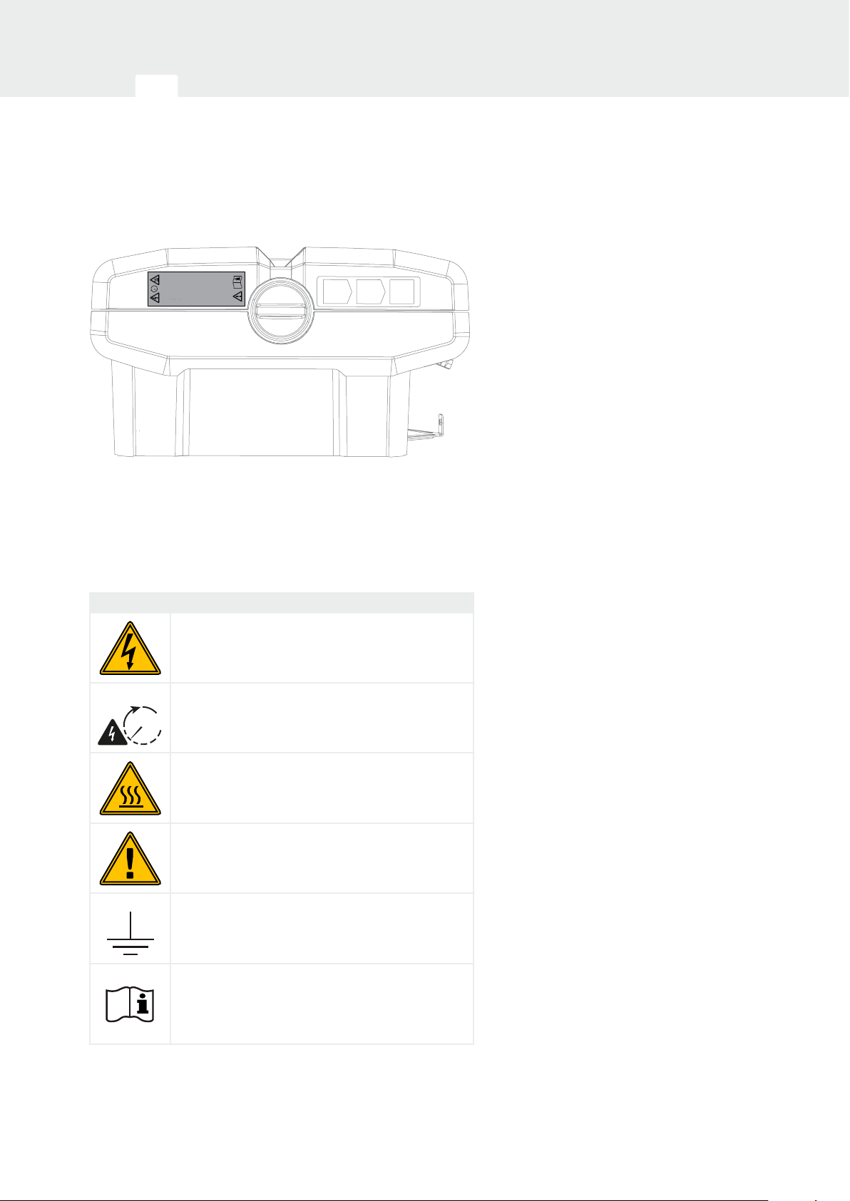
1.6 Labels on the inverter
5 min
supplies
until it is isolated from both
mains and on-site generation
Do not work on this equitment
WARNING: dual supply
Isolate on-site
generator at _________________
Isolate mains
supply at ____________________
Fig. 7: Labels on the inverter – Figure example
Signs and labels are applied to the housing of the
inverter. These signs and labels may not be altered or
removed.
Symbol Explanation
Danger due to electrical shock and discharge
Danger due to electrical shock and discharge. Wait
five minutes (discharge time of the capacitors) after
5 min
shut-down
Danger due to burns
Danger notice
Additional earth connection
Observe and read operating manual
06 / 2016 | DOC01728451 | KOSTAL operating manual PIKO inverter 3.0 - 20
18

2
34567891011121
Navibutton Verlinkung Kapitel 02
2. Device and system description
2.1 The photovoltaic system ........................................................................................................... 20
2.2 Inverter components ................................................................................................................. 22
2.3 Inverter functions ..................................................................................................................... 38
2.
06 / 2016 | DOC01728451 | KOSTAL operating manual PIKO inverter 3.0 - 20
19
Device and system description
34567891011121
2
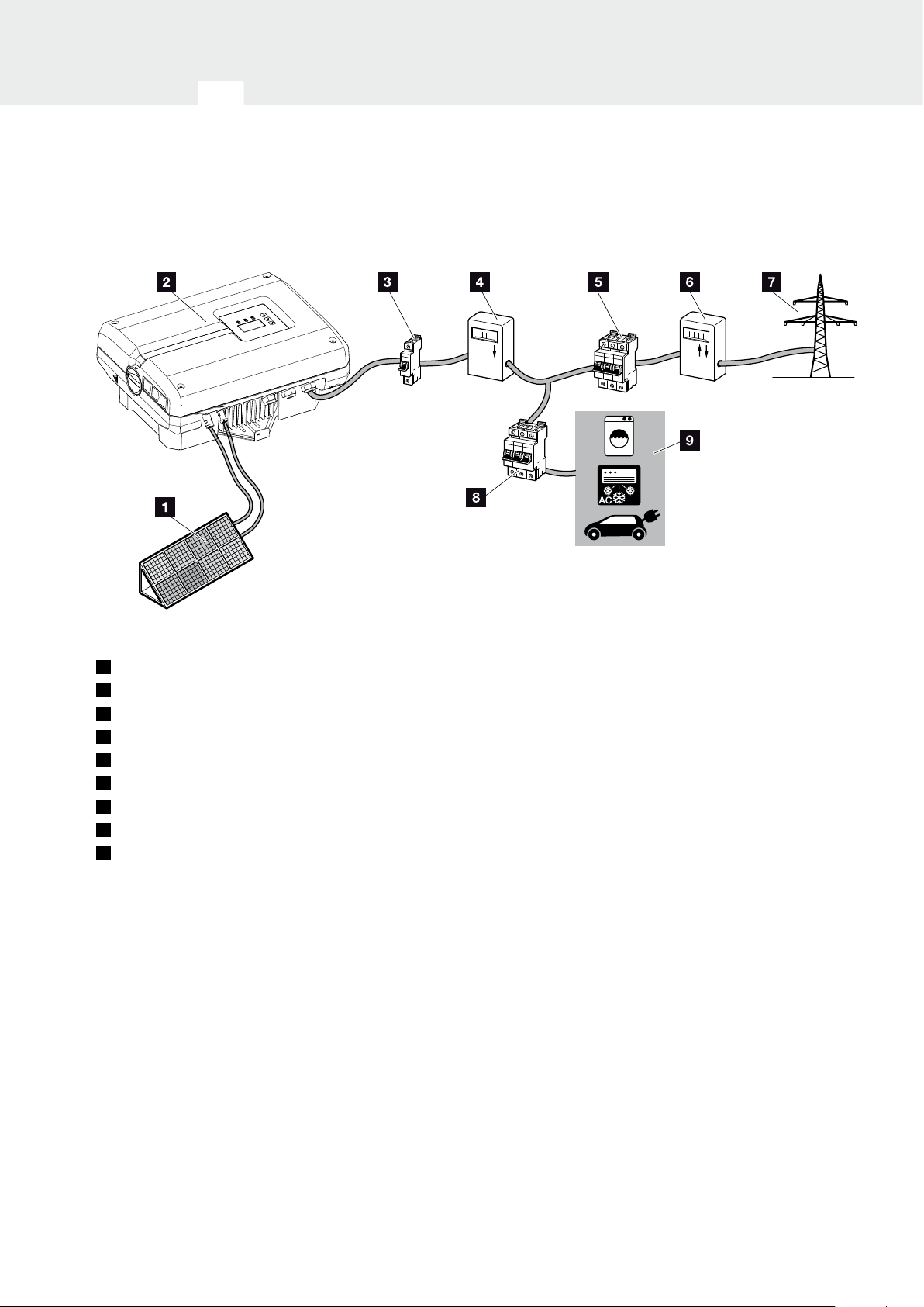
2.1 The photovoltaic system
Fig. 8: Photovoltaic system 1-phase
1
PV string
2
Inverter
3
Line circuit breaker for inverter
4
PV yield counter (optional)
5
Line circuit breaker for house
6
Feed-in procurement meter
7
Public grid
8
Line circuit breaker for energy consumers
9
Energy consumers
06 / 2016 | DOC01728451 | KOSTAL operating manual PIKO inverter 3.0 - 20
20
Device and system description
34567891011121
2
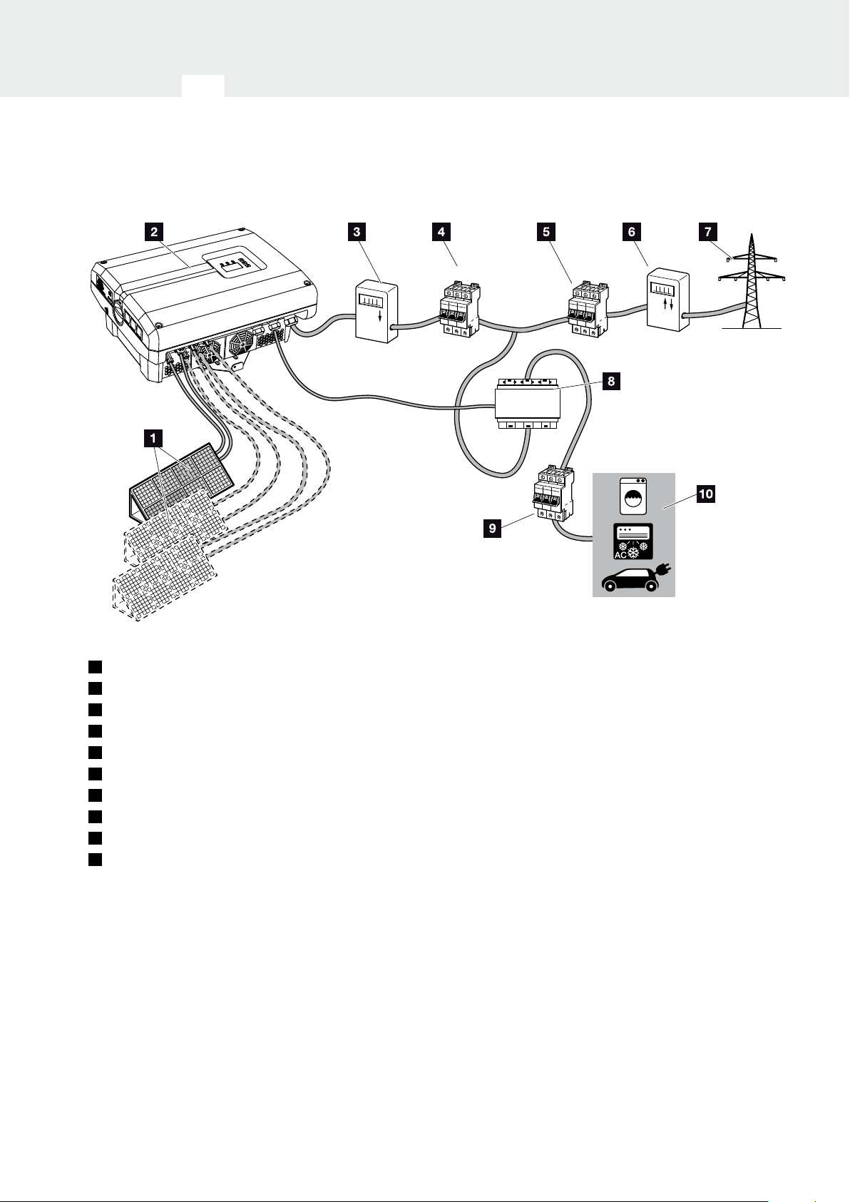
Fig. 9: Photovoltaic system 3-phase
1
PV string (2+3 optional)
2
Inverter
3
PV yield counter (optional)
4
Line circuit breaker for inverter
5
Line circuit breaker for house
6
Feed-in procurement meter
7
Public grid
8
PIKO BA Sensor (optional accessory)
9
Line circuit breaker for consumers
10
Energy consumers
06 / 2016 | DOC01728451 | KOSTAL operating manual PIKO inverter 3.0 - 20
21
Device and system description
34567891011121
2
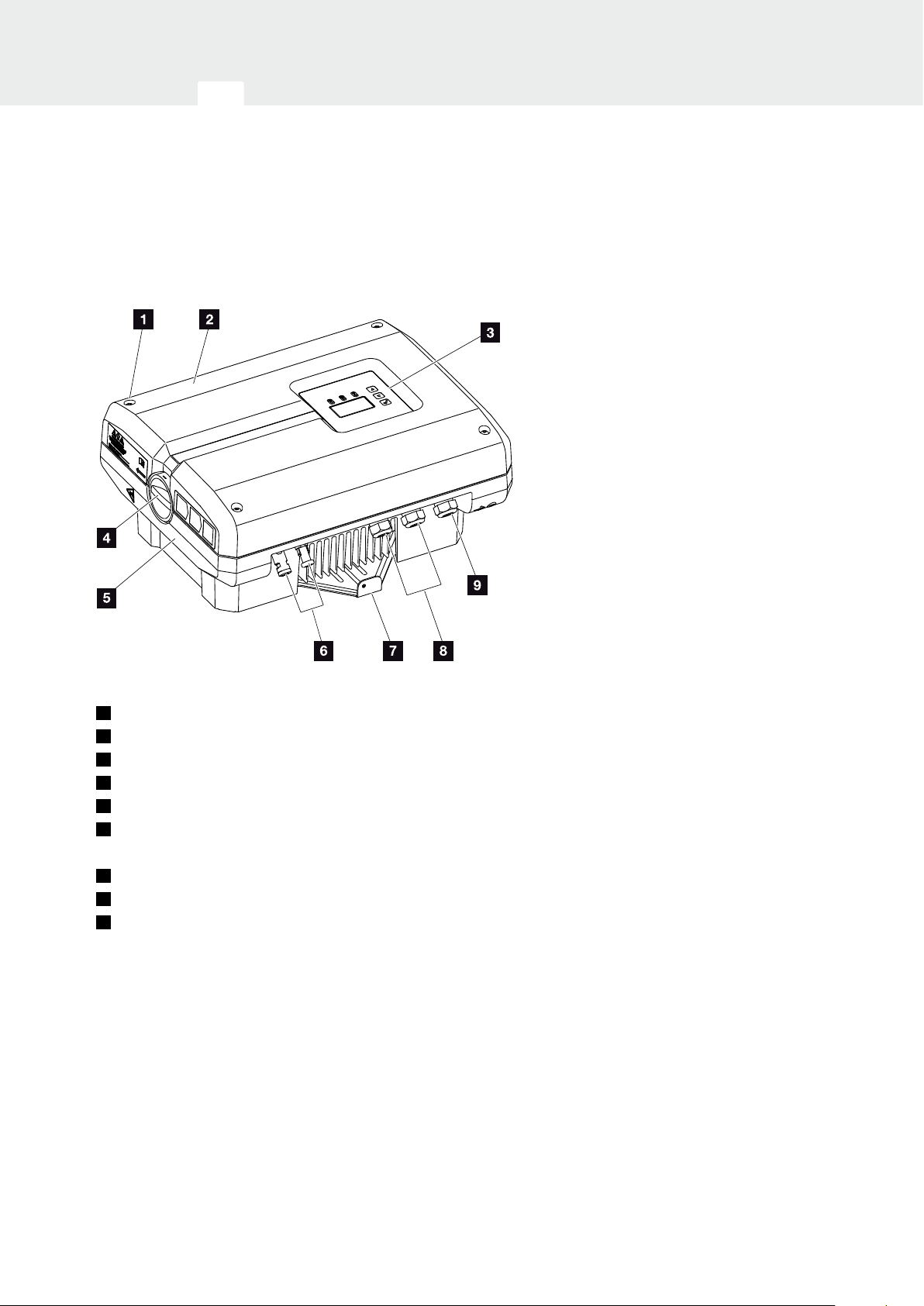
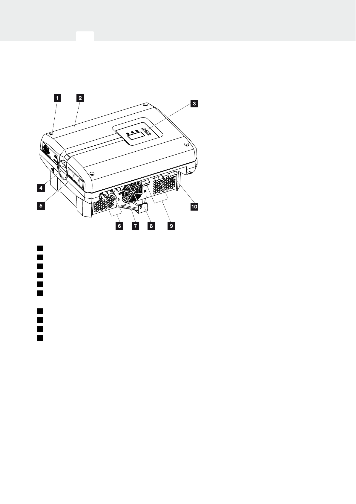
2.2 Inverter components
Exterior view of the inverter
Fig. 10: PIKO inverter 3.0 (exterior view)
1
Cover screws
2
Cover
3
Display
4
DC switch
5
Housing
6
Plug connector or cable openings to connect the
solar modules
7
Wall mount
8
Cable openings for optional communication
9
Opening for the mains cable
06 / 2016 | DOC01728451 | KOSTAL operating manual PIKO inverter 3.0 - 20
22

Device and system description
34567891011121
2
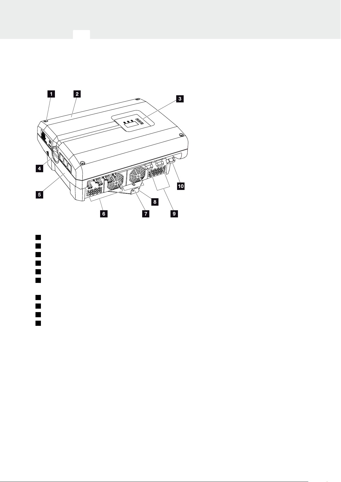
Fig. 11: PIKO inverter 4.2 (exterior view)
1
Cover screws
2
Cover
3
Display
4
DC switch
5
Housing
6
Plug connector or cable openings to connect the
solar modules
7
Fan grill (without fan)
8
Wall mount
9
Cable openings for optional communication
10
Opening for the mains cable
06 / 2016 | DOC01728451 | KOSTAL operating manual PIKO inverter 3.0 - 20
23
Device and system description
34567891011121
2
Fig. 12: PIKO inverters 4.6-8.5 (exterior view)
1
Cover screws
2
Cover
3
Display
4
DC switch
5
Housing
6
Plug connector or cable openings to connect the
solar modules
7
Fan
8
Wall mount
9
Cable openings for optional communication
10
Opening for the mains cable
06 / 2016 | DOC01728451 | KOSTAL operating manual PIKO inverter 3.0 - 20
24

Device and system description
34567891011121
2
Fig. 13: PIKO inverters 10 - 12 (exterior view)
1
Cover screws
2
Cover
3
Display
4
DC switch
5
Housing
6
Plug connector or cable openings to connect the
solar modules
7
Fan
8
Wall mount
9
Cable openings for optional communication
10
Opening for the mains cable
06 / 2016 | DOC01728451 | KOSTAL operating manual PIKO inverter 3.0 - 20
25
Device and system description
34567891011121
2
Fig. 14: PIKO inverters 15 - 20 (exterior view)
1
Cover screws
2
Cover
3
Display
4
DC switch
5
Housing
6
Plug connector or cable openings to connect the
solar modules
7
Fan
8
Wall mount
9
Cable openings for optional communication
10
Opening for the mains cable
06 / 2016 | DOC01728451 | KOSTAL operating manual PIKO inverter 3.0 - 20
26
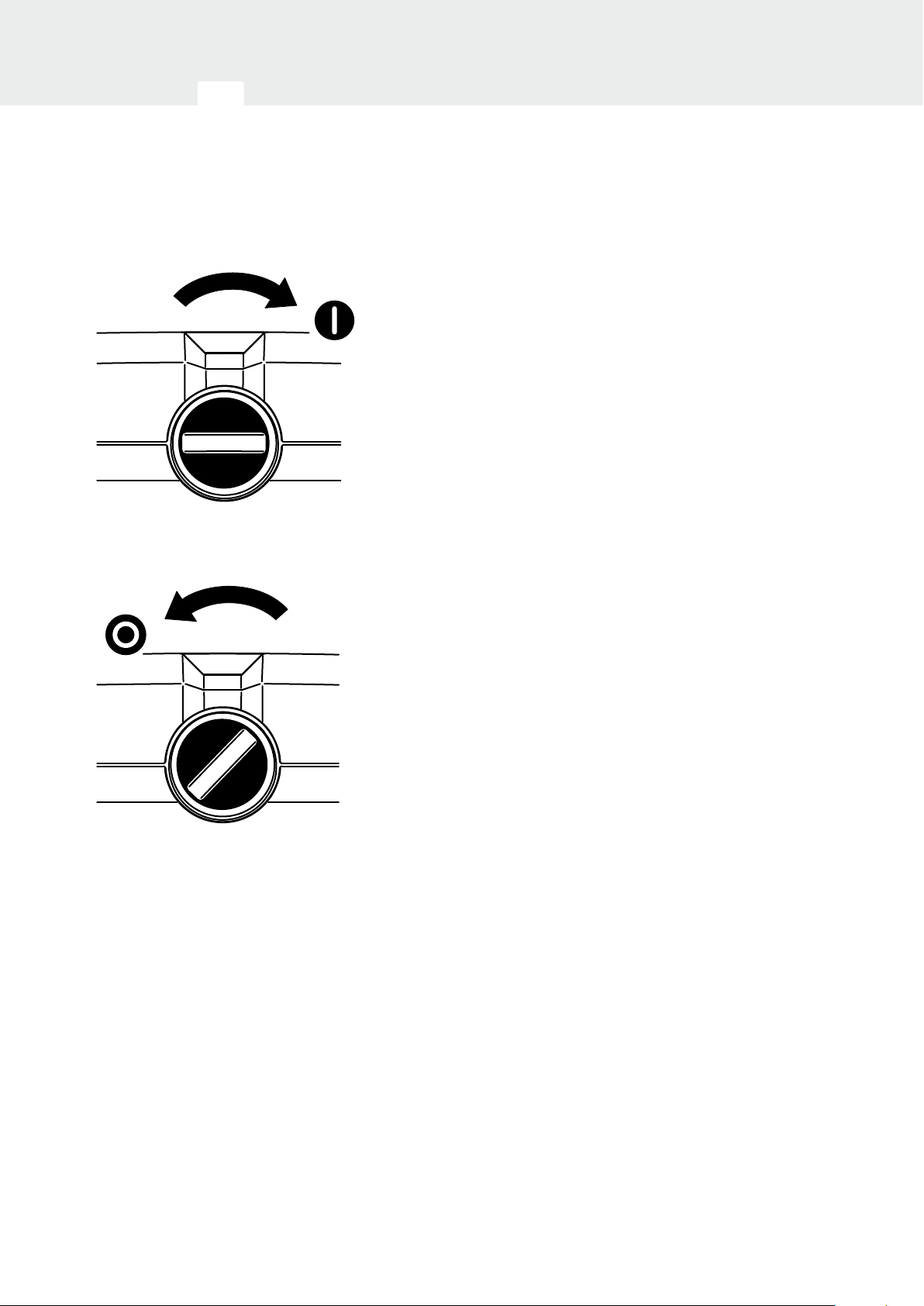
Device and system description
ON
OFF
34567891011121
2
DC switch on the inverter
Fig. 15: DC switch ON
Fig. 16: DC switch OFF
06 / 2016 | DOC01728451 | KOSTAL operating manual PIKO inverter 3.0 - 20
27
Device and system description
34567891011121
2
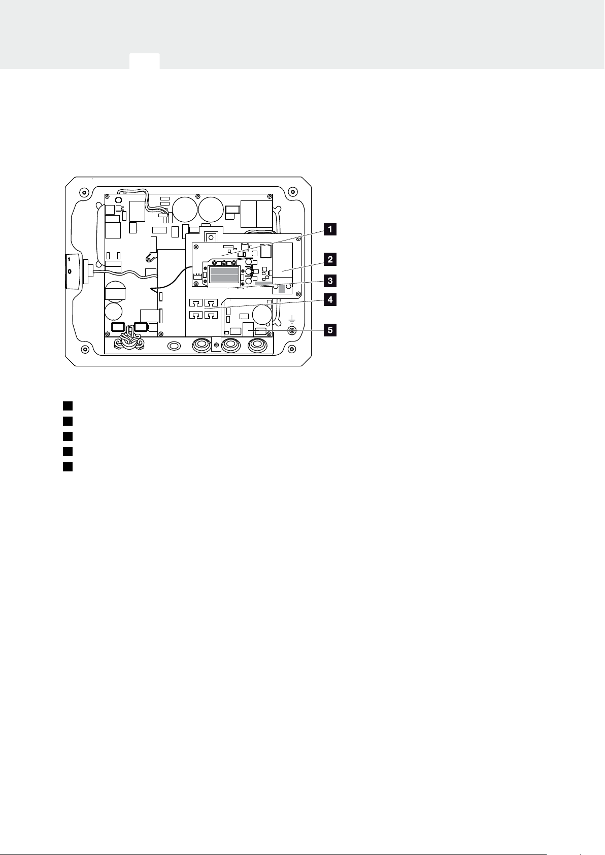
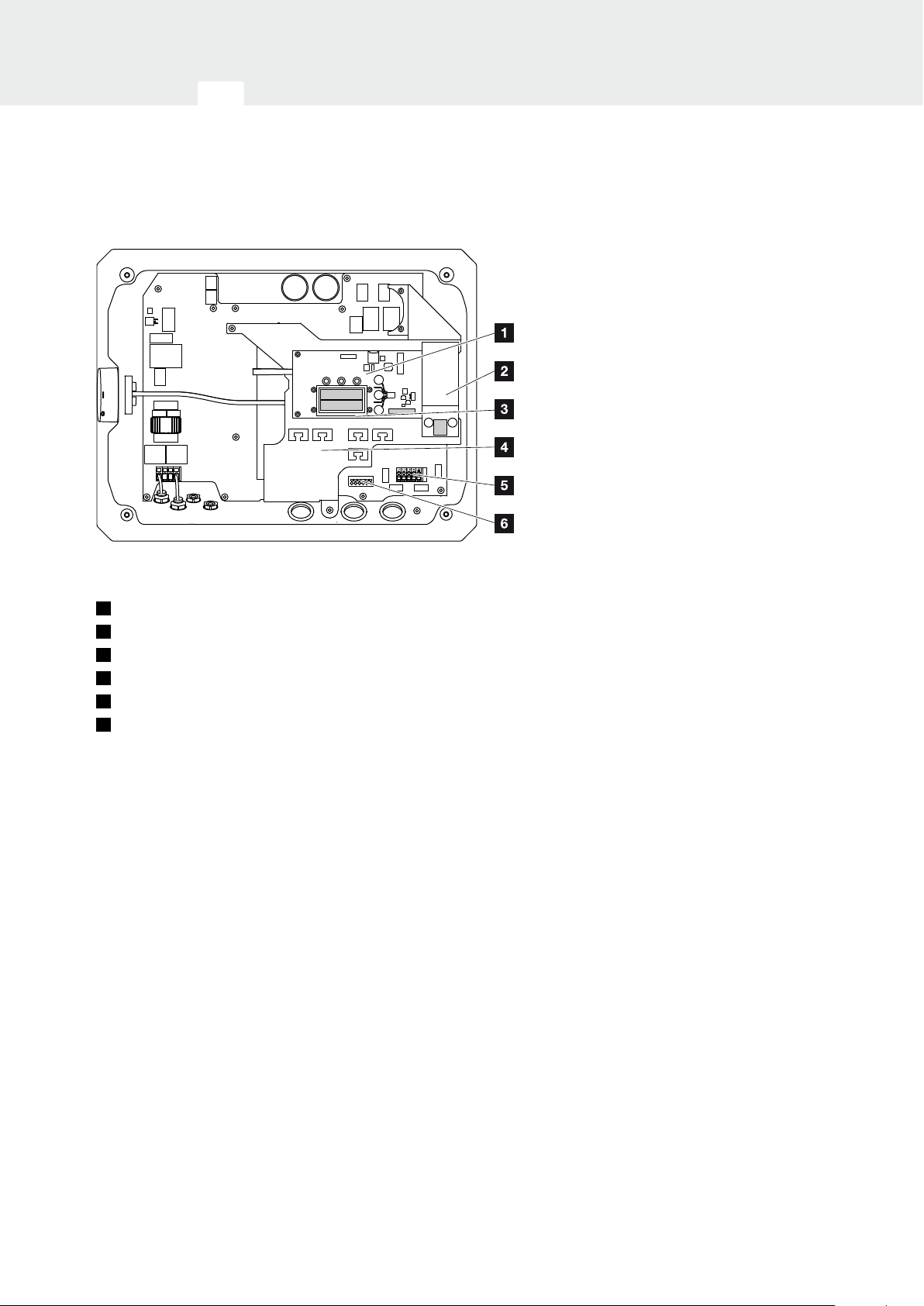
Interior view of the inverter
Fig. 17: PIKO inverter 3.0 (interior view)
1
Communication board
2
Expansion module (optional)
3
Ethernet connections (RJ45)
4
Cable tray with fastening openings
5
AC terminal
06 / 2016 | DOC01728451 | KOSTAL operating manual PIKO inverter 3.0 - 20
28
Device and system description
34567891011121
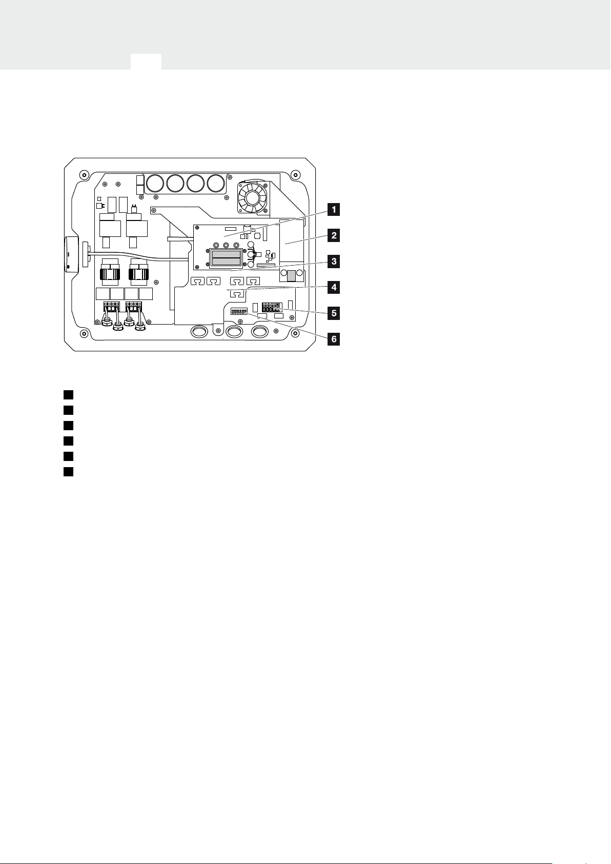
2
Fig. 18: PIKO inverter 4.2 (interior view)
1
Communication board
2
Expansion module (optional)
3
Ethernet connections (RJ45)
4
Cable tray with fastening openings
5
AC terminal
6
Terminal for sensor lines of PIKO BA Sensor
06 / 2016 | DOC01728451 | KOSTAL operating manual PIKO inverter 3.0 - 20
29
Device and system description
34567891011121
2
Fig. 19: PIKO inverters 4.6 - 8.5 (interior view)
1
Communication board
2
Expansion module (optional)
3
Ethernet connections (RJ45)
4
Cable tray with fastening openings
5
AC terminal
6
Terminal for sensor lines of PIKO BA Sensor
06 / 2016 | DOC01728451 | KOSTAL operating manual PIKO inverter 3.0 - 20
30
 Loading...