

Page 1
GB
COOKER HOOD - User instructions
CZ
ODSAVAČ PAR – uživatelská příručka
DK
EMHÆTTE - Brugervejledning
FIN
LIESITUULETIN – Käyttöohje
GR
ΑΠΟΡΡΟΦΗΤΗΡΑΣ ΣΕ ΕΚΔΟΣΗ ΑΠΟΡΡΟΦΗΣΗΣ – Εγχειρίδιο χρήσησ
H
ELSZÍVÓ KÜRTŐ – Használati utasítás
N
AVTREKKSKAPPE – Bruksanvisning
PL
OKAPY ZASYSAJĄCY - instrukcja obsługi
R
HOTĂ ASPIRANTĂ – Manual de utilizare
RUS
ВЫТЯЖНОЙ КОЛПАК - Руководство пользователя
S
SPISKÅPA – Bruksanvisning
Page 2
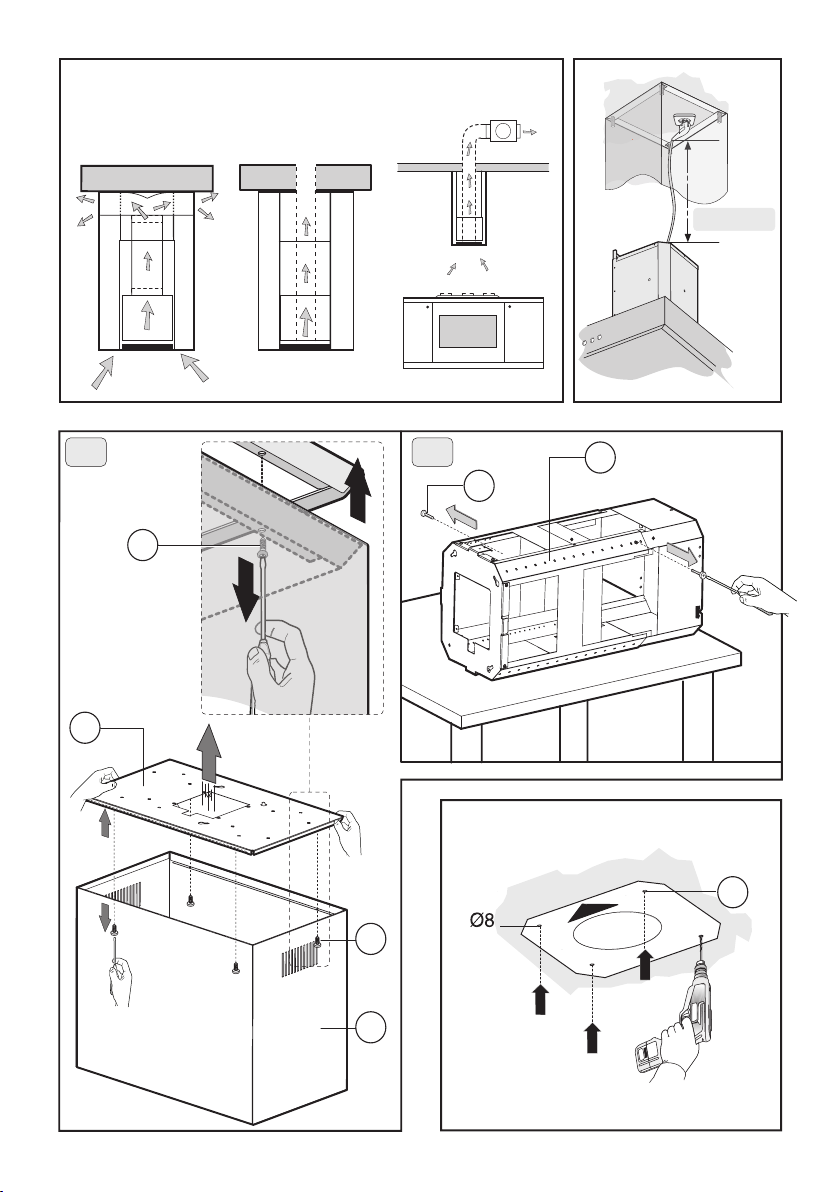
Fig.1
A
B
C
M
max 80 cm
2 A 2 B
D
D
D
L
B
A
X
Fig.2 Fig.3
- 3 -
Page 3
D
C
B
Fig.4
D
E
M
E
D
D
C
Fig.5
B
- 4 -
Page 4
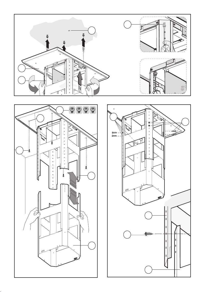
Fig.6
D
X
X
C
B
D
E
G
G
Fig.7
B
B
G
C
C
Fig.8
- 5 -
Page 5
M
Fig.9
Fig.10
11D
O
11C
N
N
N
11B
Fig.11
O
O
Max 3 mm
11A
- 6 -
O
N
Page 6
D
Fig.12
L
E
D
H
F
Fig.13
- 7 -
Fig.14
Page 7
Y
Fig.15
N
Y
Y
A
Y
Fig.16
Fig.17
B
C
- 8 -
Page 8
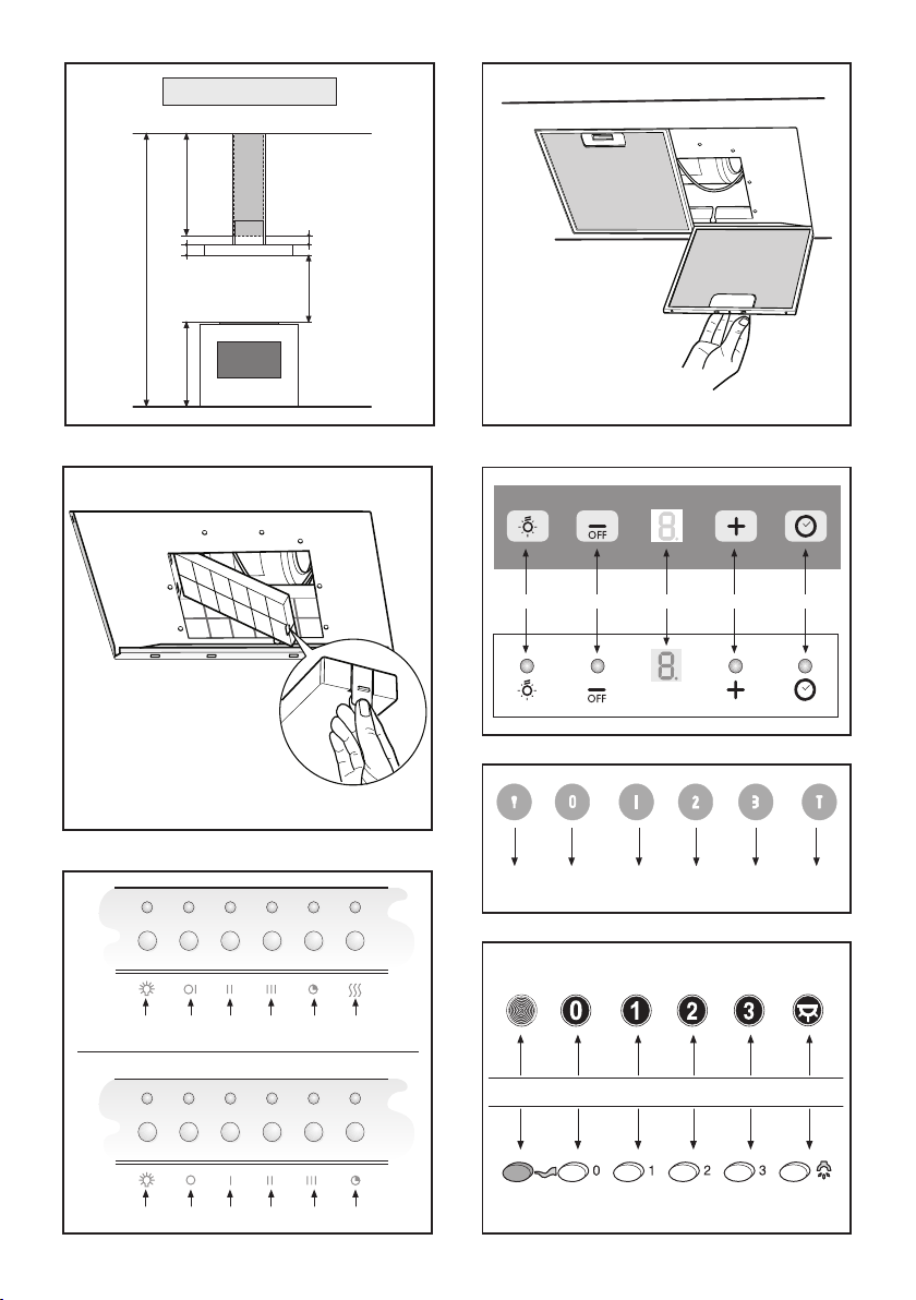
X = C - (90+A+650+B)
X
Fig.18
Fig.20
A
C
B
90
650
Fig.19
A B C D E
Fig.21
A
B
Fig.22
B
A
C
E
D
F
Fig.23
A
A
B
A
B
D
C
D
C
F
E
C
B
G
- 9 -
B
Fig.24
F
E
E
D
A
Page 9

ENGLISH
GENERAL
Carefully read the following important information regarding installation safety and maintenance. Keep this information booklet accessible for further consultations.
The appliance has been designed for use in the ducting
version (air exhaust to the outside – Fig.1B), filtering
version (air circulation on the inside – Fig.1A) or with
external motor (Fig.1C).
SAFETY PRECAUTION
1. Take care when the cooker hood is operating simulta-
neously with an open fireplace or burner that depend on
the air in the environment and are supplied by other than
electrical energy, as the cooker hood removes the air
from the environment which a burner or fireplace need
for combustion. The negative pressure in the environment
must not exceed 4Pa (4x10⁻⁵ bar). Provide adequate
ventilation in the environment for a safe operation of the
cooker hood.
Follow the local laws applicable for external air evacuation.
Before connecting the model to the electricity network:
- control the data plate (positioned inside the appliance)
to ascertain that the voltage and power correspond to
the network and the socket is suitable. If in doubt ask a
qualified electrician.
- If the power supply cable is damaged, it must be
replaced with another cable or a special assembly, which
may be obtained direct from the manufacturer or from
the Technical Assistance Centre.
2. WARNING !
In certain circumstances electrical appliances may
be a danger hazard.
A) Do not check the status of the filters while the
cooker hood is operating
B) Do not touch bulbs or adjacent areas, during or
straight after prolonged use of the lighting
installation.
C) Flambè cooking is prohibited underneath the
cooker hood
D) Avoid free flame, as it is damaging for the filters
and a fire hazard
E) Constantly check food frying to avoid that the
overheated oil may become a fire hazard
F) Disconnect the electrical plug prior to any maintenance.
G) This appliance is not intended for use by young
children or infirm persons without supervision
H) Young children should be supervised to ensure
they do not play with the appliance
I) There shall be adequate ventilation of the room
when the rangehood is used at the same time as appliances burning gas or other fuels
L) There is a risk of fire if cleaning is not carried out
in accordance with the instructions
This appliance conforms to the European Directive EC/
2002/96, Waste Electrical and Electronic Equipment
(WEEE). By making sure that this appliance is disposed
of in a suitable manner, the user is helping to prevent
potential damage to the environment or to public health.
symbol on the product or on the accompanying
The
paperwork indicates that the appliance should not be
treated as domestic waste, but should be delivered to a
suitable electric and electronic appliance recycling
collection point. Follow local guidelines when disposing
of waste. For more information on the treatment, re-use
and recycling of this product, please contact your local
authority, domestic waste collection service or the shop
where the appliance was purchased.
INSTALLATION INSTRUCTIONS
Assembly and electrical connections must be carried
out by specialised personnel.
• Electric Connection
The appliance has been manufactured as a class II,
therefore no earth cable is necessary.
The connection to the mains is carried out as follows:
BROWN = L line
BLUE = N neutral
If not provided, connect a plug for the electrical load
indicated on the description label. Where a plug is provided, the cooker hood must be installed in order that
the plug is easily accessible.
An omnipolar switch with a minimum opening of 3mm
between contacts, in line with the electrical load and local
standards, must be placed between the appliance and
the network in the case of direct connection to the
electrical network.
• The minimum distance between the support surfaces
of the cooking pots on the cooker top and the lowest
part of the cooker hood must be at least 65 cm.
If a connection tube composed of two parts is used, the
upper part must be placed outside the lower part.
Do not connect the cooker hood exhaust to the same
conductor used to circulate hot air or for evacuating fumes
from other appliances generated by other than an
electrical source.
Before proceeding with the assembly operations, remove
the anti-grease filter(s) (Fig.19) so that the unit is easier
to handle.
In the case of assembly of the appliance in the suction
version prepare the hole for evacuation of the air.
• We recommend the use of an air exhaust pipe with a
diameter of 150. If a pipe with a smaller diameter is used,
the efficiency of the product may be reduced and its
operation may become noisier
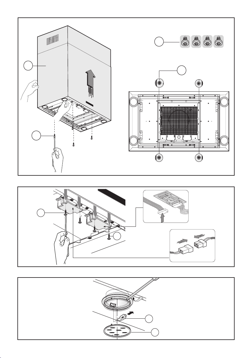
• Replacing halogen light bulbs (Fig. 17).
To replace the halogen light bulbs B, remove the glass
pane C using a lever action on the relevant cracks.
Replace the bulbs with new ones of the same type.
- 10 -
GB
Page 10

Caution: do not touch the light bulb with bare hands.
Note!
- When installing this product we recommend you seek
the help of another individual.
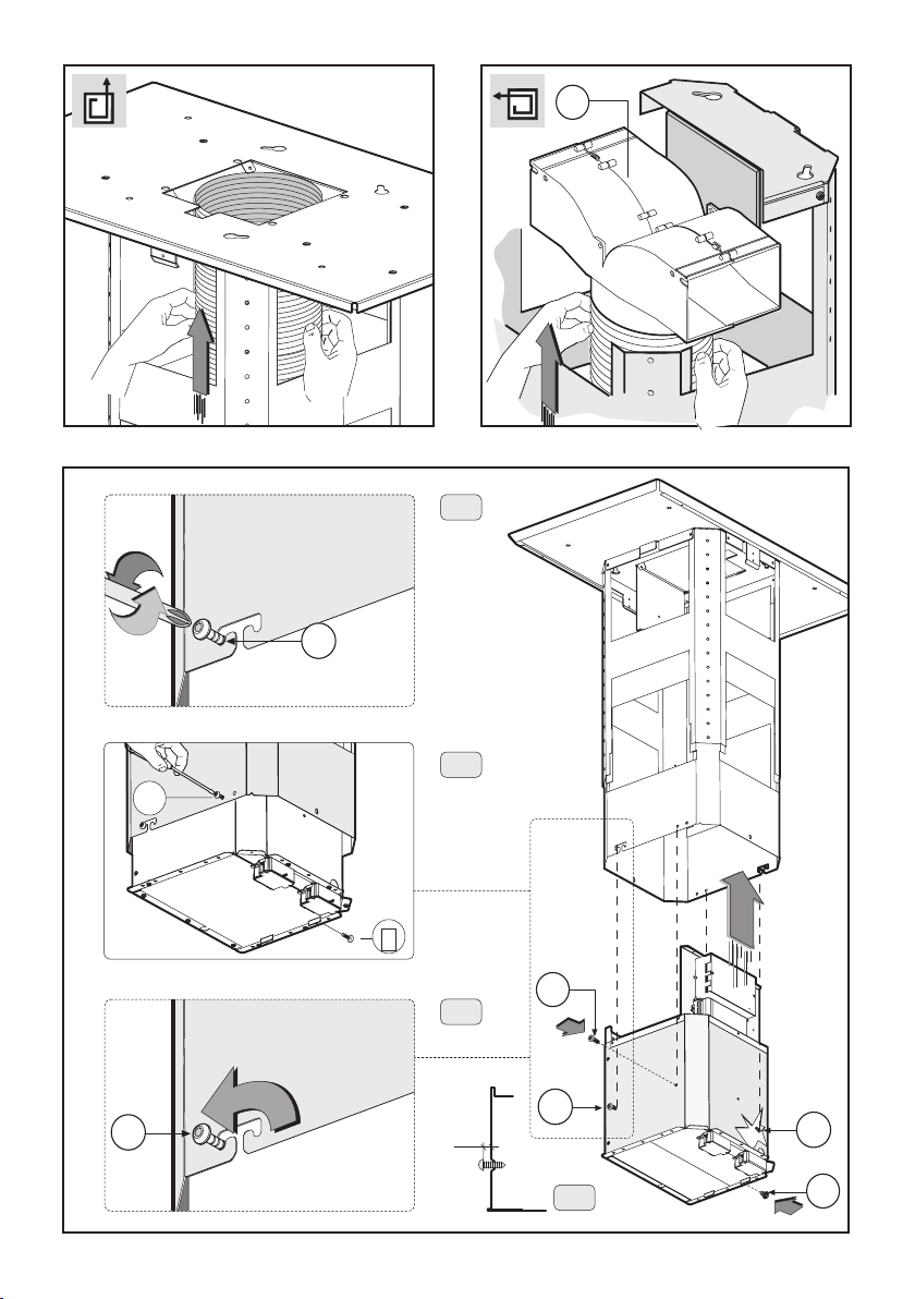
• Hood assembly
- Before installing the cooker hood, open the packaging,
take out the upper duct L and remove the 4 screws D
joining the upper duct to the duct fixing bracket C (Fig.
2A).
Remove the structure from the packaging and remove
the 2 screws A to separate the upper part from the lower
part (fig.2B).
- Position hole template on the ceiling paying attention
that the arrow is positioned on the same side as the
appliance controls (Fig.3).
Make 4, Ø8 holes in the ceiling and drive in 3 screws
without completely tightening them. Pay attention not to
insert the screw into the hole marked with an X on the
hole template (the screws and expansion plugs must be
suitable for the type of wall).
Extractor hood
- Join the duct fixing bracket C to the upper frame B
using the four screws D (Fig. 4).
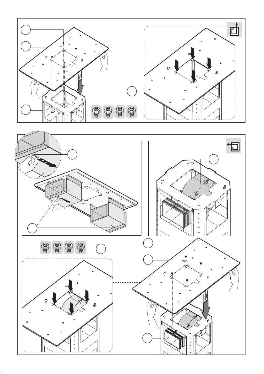
Filter hood
- Before joining the fixing bracket C to the upper frame
B, shift the deflector E inwards using the corresponding
slots (Fig. 5).
- In the Filter version, the air diverter is fitted to the upper
frame.
- Join the duct fixing bracket C to the upper frame B
using the four screws D (Fig. 5).
- Take the upper part of the structure B (fig.6) and insert
the 3 slots onto the 3 screws that are not completely
tightened.
Rotate slightly to fit (fig.6) .
Drive in the fourth screw X and tighten the remaining 3
to allow definitive blocking of the upper part of structure
B.
We recommend the duct fixing bracket C is securely fixed
in place by tightening another 4 screws D into the safety
holes (Fig. 7).
- Take the lower part of the telescopic structure C and
insert it into the upper structure B (fig.7).
Adjust the height by referring to the amounts indicated
in (fig.18) and block it using the 8 screws G that are
supplied (fig.8).
- Suction version: fix the flexible pipe to the prepared
air evacuation hole (fig. 9).
- Filter hood: connect the flexible hose to the deflector
M as indicated in (Fig. 10); the active carbon filters should
be fitted to the extraction assembly inside the hood (Fig.
20).
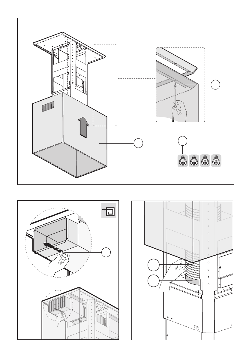
- Unscrew the 2 screws O, max 3 mm (Fig.11A).
Introduce the extraction assembly into the frame,
ensuring that the screws O (loosened previously) hook
into the slots as indicated in (Fig. 11 B).
Drive in the 2 screws N (supplied) and tighten the 2
screws O (Fig.11C-D).
- Take the upper duct L and fit it to the duct fixing bracket
C using the 4 screws D (Fig. 12).
- For the filter version, once the duct is fixed to the
frame the RHS and LHS deflectors E should be moved
outwards, using the corresponding slots (Fig. 13) so that
they are aligned with the air outlet screen of the hose.
- Fix the air evacuation pipe H (not supplied) onto the
connection flange F (Fig.14)
- Take the locking device N and join it to the upper duct,
then fix it in place using the 4 screws Y (Fig. 15).
- Electrical connection
Before connecting the appliance to the electricity supply,
remove the 4 screws A, open the covers and perform
the necessary electrical connections between the body
of the cooker hood and the motor assembly (Fig. 16).
USE AND MAINTENANCE
• We recommend that the cooker hood is switched on
before any food is cooked. We also recommend that the
appliance is left running for 15 minutes after the food is
cooked, in order to thoroughly eliminate all contaminated
air.
The effective performance of the cooker hood depends
on constant maintenance; the anti-grease filter and the
active carbon filter both require special attention.
• The anti-grease filter is used to trap any grease particles
suspended in the air, therefore is subject to saturation
(the time it takes for the filter to become saturated
depends on the way in which the appliance is used).
The acrylic filter, which is found resting on the grille,
should be replaced when the text, visible through the
grille, changes colour and the ink spreads; the new filter
should be fitted in such a way that the text can be seen
through the grille from outside the cooker hood.
If the filters do not have any text on them, or if metal
filters or aluminium panel filters are used, they should
be washed every 2 months in order to prevent the risk of
fire. To wash the filters, proceed as follows:
- Remove the filter from the grille and wash it using a
solution of water and neutral liquid detergent, leaving
the dirt to soften.
- Rinse thoroughly with warm water and leave to dry.
The metal filters and/or aluminium panel are also
dishwasher safe. If the filters are made using aluminium,
or if an aluminium panel is used, after a few washes the
colour may change. This does not mean they have to be
replaced.
If the replacement and washing instructions are not
followed, the anti-grease filters may present a fire hazard.
• The active carbon filters are used to purify the air which
is released back into the room. The filters are not
washable or re-usable and must be replaced at least once
every four months. The active carbon filter saturation level
depends on the frequency with which the appliance is
used, the type of cooking performed and the regularity
with which the anti-grease filters are cleaned.
• Remove build-up from the fan and other surfaces of
the cooker hood regularly using a cloth moistened with
denatured alcohol or non-abrasive neutral liquid
detergent.
• The light on the cooker hood is designed for use during
cooking and not for general room illumination. Extended
use of the light reduces the average duration of the bulb.
COMMANDS: (Fig.21)
Push-button A = on/off lights switch
Push-button B = on/off cooker hood switch. The appli-
- 11 -
Page 11

ance switches on at speed level 1, If the cooker hood is
on depress the push-button for 2 sec. to switch off the
cooker hood. If the cooker hood is at speed level 1 it will
not be necessary to depress the push-button to switch
the cooker hood off. Decreases the motor speed.
Display C = indicates the motor speed level selected
and activates the timer.
Push-button D = switches on the cooker hood. Increases the motor speed. Touching the key at 3rd speed,
the intensive function runs for 10', then the appliance go
back to work at the original speed. During this function
the display blinks.
Key E = The Timer times the functions on activation for
15 minutes, after which they are switched off. The Timer
is deactivated by re-pressing Key E. When the Timer is
activated the decimal point must flash on the display.
The Timer cannot be activated if the intensive speed is
functioning.
The “clean air” function is activated by pressing key E
for 2 seconds when the appliance is switched off. This
switches the motor on for 10 minutes every hour at the
first speed. During functioning a rotary movement of the
peripheral segments must be visualised on the display.
When this time has passed the motor switches off and
the fixed letter “C” must be visualised on the display
until the motor re-starts after 50 minutes for another 10
minutes and so on. Press any key apart from the light
keys to return to normal functioning. Press key E to
deactivate the function.
• Active carbon/grease filter saturation:
- When display item C flashes, at a speed where it
alternates with the letter F (e.g. 1 and F), the grease
filters must be washed.
- When display item C flashes, at a speed where it
alternates with the letter A (e.g. 1 and A), the carbon
filters must be replaced.
After the clean filter has been positioned correctly, the
electronic memory must be reset by pressing button A
for approximately 5 seconds, until the indication F or A
shown on the display C stops flashing.
• COMMANDS: ELECTRONIC (Fig.22A):
A = LIGHT
B = OFF/SPEED I
C = SPEED II
D = SPEED III
E = AUTOMATIC STOP TIMER – 15 minutes (*)
F = FILTER SATURATION RESET LIGHT
When the “filter saturation” light flashes, the anti-grease
filters must be washed. When the light comes on without
flashing, the anti-grease filters must be washed and the
carbon filters replaced (in case of operation whit the recycling version). When this operation has been completed, press the key to reset it.
• COMMANDS:
(Fig.23) LUMINOUS - (Fig.22B) ELECTRONICthe key
symbols are explained below:
A = LIGHT
B = OFF
C = SPEED I
D = SPEED II
E = SPEED III
F = AUTOMATIC STOP TIMER - 15 minutes (*)
• If your appliance does not have the INTENSIVE speed
function, press key E for two seconds and it will be
activated for 10 minutes after which it will return to the
previously set speed. When the function is active the LED
flashes. To interrupt it before the 10 minutes have expired
press key E again.
• By pressing key F for two seconds (with the hood
switched off) the “clean air” function is activated. This
function switches the appliance on for ten minutes every
hour at the first speed. As soon as this function is activated the motor starts up at the first speed for ten
minutes, During this time key F and key C must flash at
the same time.
After ten minutes the motor switches off and the LED of
key F remains switched on with a fixed light until the
motor starts up again at the first speed after fifty minutes and keys F and C start to flash again for ten minutes and so on.
By pressing any key for the exclusion of the hood light
the hood will return immediately to its normal functioning
(e.g. if key D is pressed the “clean air” function is deac-
tivated and the motor moves to the 2nd speed straight
away. By pressing key B the function is deactivated).
(*) The “automatic stop timer” delays stopping of the
hood, which will continue functioning for 15 minutes at
the operating speed set at the time this function is
activated.
• Active carbon/grease filter saturation:
- When button A flashes at a frequency of 2 seconds,
the grease filters must be cleaned.
- When button A flashes at a frequency of 0.5 seconds,
the carbon filters must be replaced.
After the clean filter has been replaced, the electronic
memory must be reset by pressing button A for
approximately 5 seconds, until the light on the button
stops flashing.
•COMMANDS:(Fig.24A)MECHANICAL_(Fig.24B) Elliptic
the key symbols are explained below:
A = LIGHT
B = OFF
C = SPEED I
D = SPEED II
E = SPEED III
G = MOTOR WORKING indicator
THE MANUFACTURER DECLINES ALL
RESPONSIBILITY FOR EVENTUAL DAMAGES
CAUSED BY BREACHING THE ABOVE WARNINGS.
- 12 -
Page 12
ČESKY
POLSCPOLSC
CZ
ÚVOD’
Přečtěte si pozorně obsah návodu, protože poskytuje
důležité informace týkající se bezpečné instalace,
používání i údržby zařízení. Uchovejte si návod pro
jakoukoliv budoucí potřebu. Přístroj je určen k odsávání
(odvádění vzduchu ven – obr.1B), filtrování (recyklace
vzduchu v místnosti – obr.1A) nebo k použití s externě
umístěným motorem (obr.1C).
BEZPECNOSTNÍ OPATRENÍ
1. Vyžaduje se opatrnost, jestliže jsou současně v
činnosti odsávač par a jiný hořák nebo tepelné zařízení
závisející na vzduchu místnosti a napájené jinou energií
než elektrickou, protože odsávač par spotřebovává
vzduch z okolí, který hořák nebo jiné tepelné zařízení
potřebují ke spalování. Negativní tlak nesmí překročit 4Pa
–5
(4x10
bar). K bezpečnému provozu je tedy nutná
odpovídající ventilace místnosti. Při odvádění vzduchu
do vnějšího prostředí je nutné se řídit platnými předpisy
Vaší země.
Před napojením modelu na elektrickou síť:
- Zkontrolujte tabulku s údaji umístěnou uvnitř přístroje
a ověřte si, že napětí a výkon odpovídají místní síti a
rovněž zásuvka je vhodná. V případě jakékoliv pochyby
se poraďte s kvalifikovaným elektrikářem.
- Je-li napájecí kabel poškozen, musí být nahrazen
speciálním kabelem nebo sadou, které jsou k dispozici
u výrobce nebo v jeho servisním středisku.
2. UPOZORNĚNÍ !
Za určitých okolností mohou být elektrické
spotřebiče nebezpečné.
A) Neprovádějte kontrolu filtrů se zapnutým
spotřebičem
B) Nedotýkejte se žárovek a prostoru kolem nich
behem užití nebo ihned po dlouhodobém užití
osvetlovacího zarízení.
C) Nedotýkejte se žárovek, bylo-li zařízení déle v
chodu
D) Je zakázáno upravovat pokrmy manipulí přímého
ohně pod fungujícím odsávačem
E) Vyvarujte se volnému plameni, je škodlivý pro
filtry a mohl by způsobit požár
F) Při smažení jídel zajistěte, aby se rozpálený olej
nevznítil
G) Zařízení nebylo navrženo pro použití dětmi nebo
nesvéprávnými osobami bez dozoru.
H) Zkontrolujte, zda si děti nehrají se zařízením.
I) Před provedením jakékoliv údržby vypněte
přístroj z elektrické sítě.
Toto zařízení je označeno v souladu s Evropskou
směrnicí 2002/96/ES, Waste Electrical and Electronic
Equipment (WEEE). Tím, že se uživatel ujistí o správné
likvidaci tohoto výrobku, přispívá k předcházení
případným negativním následkům na životní prostředí a
na zdraví.
Symbol
poukazuje na to, že se s tímto výrobkem nesmí zacházet
jako s běžným domovním odpadem, ale musí se odeslat
do vhodné sběrny určené pro recyklaci elektrických a
elektronických zařízení. Zařízení se musíte zbavit
v souladu s místními předpisy pro likvidaci
odpadu.Podrobnější informace o zacházení s tímto
výrobkem, jeho opětovným použitím a recyklací můžete
získat, když se obrátíte na příslušný místní úřad, sběrnou
službu domovního odpadu nebo obchod, ve kterém jste
výrobek zakoupili.
na výrobku nebo na přiložené dokumentaci
NÁVOD K INSTALACI
Operace spojené s montáží a elektrická napojení musí
být provedeny pouze odborným personálem.
• Elektrické zapojení
Zařízení je vyrobeno v II. třídě, a proto žádný vodič nesmí
být uzemněn.
Napojení k elektrické síti musí být provedeno následovně:
HNĚDÁ = L vodič
MODRÁ = N neutrální vodič
Na přívodní kabel, pokud ji již neobsahuje, namontujte
zástrčku normalizovanou pro příkon uvedený v
technických charakteristikách výrobku.
V případě přímého zapojení na elektrickou síť je nezbytné
přístroj připojit přes vícepólový spínač s minimální
vzdáleností 3 mm mezi rozpojenými kontakty, dostatečně
dimenzovaný a odpovídající platným normám.
• Minimální vzdálenost mezi opěrnou plochou varných
nádob na varném zažízení a nejnižším bodem
kuchyňského krytu musí být alespoň 65 cm.
Pokud by došlo k užití spojovací trubky složené ze dvou
nebo více částí, horní část se musí nacházet vně části
spodní. Nenapojujte vývod odsávače na potrubí, ve
kterém proudí teplý vzduch nebo které je používáno
k evakuaci kouře z přístrojů, jež jsou napájeny jinou
energií než elektrickou. Před zahájením montáže
odstraňte protitukový filtr (filtry), což vám umožní
snadnější zacházení s přístrojem. (Obr.19).
V případě montáže přístroje ve verzi odsávače je třeba
připravit otvor k evakuaci vzduchu.
• Doporučuje se použití kouřové trubky s průměrem 150.
Použití redukce by mohlo negativně ovlivnit vlastnosti
výrobku a zvýšit hlučnost
• Výměna halogenových žárovek (obr. 17).
Při výměně halogenových žárovek B sejměte sklíčko C
po jeho nadzvednutí v místě příslušných otvorů.Žárovky
nahraďte novými žárovkami stejného druhu.
Upozornění:Nedotýkejte se žárovky holýma rukama.
Poznámka!
- Při instalaci tohoto výrobku se doporučuje využít pomoci
druhé osoby.
- 13 -
Page 13

• Montáž krytu:
- Před provedením instalace odsavače otevřete obal,
uchopte horní kouřovou trubku L a odšroubujte 4 šrouby
D, které spojují horní kouřovou trubku s upevňovací
konzolou kouřové trubky C (obr. 2A).
- Vyjměte celou strukturu z obalu a odstraňte dva šrouby
A za účelem oddělení horní části od části spodní (Obr.2B).
- Umístěte vrchní část děrování na strop a dávejte pozor,
aby se šipka nacházela na stejné straně, kde se nachází
ovládání přístroje (Obr.3).
Vytvořte 4 otvory Ř8 do stropu a zašroubujte 3 šrouby
bez toho, abyste je zcela utáhli a dávejte pozor, abyste
nezašroubovali šroub do otvoru označeného X na vrcholu
děrování (šrouby a roztahovací špalíčky musí být vhodné
pro typ stěny).
Odsávací verze
- Slícujte upevňovací konzolu kouřové trubky C s horní
strukturou B prostřednictvím čtyř šroubů D (obr. 4).
Filtrační verze
- Před slícováním upevňovací konzoly C s horní strukturou
B přesuňte směrem dovnitř vychylovač E prostřednictvím
příslušných podélných otvorů (obr. 5).
- U filtrační verze je vychylovač vzduchu namontován na
horní struktuře.
- Slícujte upevňovací konzolu kouřové trubky C s horní
strukturou B prostřednictvím čtyř šroubů D (obr. 5).
- Uchopte horní část struktury B (Obr.6) a umístěte ji na
3 šrouby, jež nebyly zcela zašroubovány v souladu
s třemi otvory.
Proveďte malou rotaci za účelem začlenění. (Obr.6) .
Zašroubujte čtvrtý šroub X a dotáhněte ostatní tři šrouby,
čímž umožníte definitivní upevnění horní části struktury
B.
Doporučujeme vám upevnit upevňovací konzolu kouřové
trubky C prostřednictvím dalších 4 šroubů D k příslušným
bezpečnostním otvorům (obr. 7)
- Uchopte spodní část teleskopické struktury C a začleňte
ji do vrchní struktury B (obr.7).
Nastavte požadovanou výšku s ohledem na vzdálenosti
určené na Obr.18 a zablokujte ji pomocí 8 šroubů G
v dotaci.(Obr.8).
- Verze odsávač: upevněte ohebnou trubku k předem
připravenému otvoru k evakuaci vzduchu (Obr. 9).
- Filtrační verze: Připojte hadici k vychylovači M
způsobem vyznačeným na (obr. 10); filtry s aktivním uhlím
musí být aplikovány k odsávací jednotce, umístěné uvnitř
odsavače (obr. 19).
- Odšroubujte o max 3 mm 2 šrouby O (Obr. 11A).
Vložte odsávací jednotku dovnitř struktury a dbejte
přitom, aby se předem odšroubované šrouby O zachytily
podélnými otvory, jak je naznačeno na (obr. 11 B).
Zašroubujte 2 šrouby N (v dotaci) a dotáhněte 2 šrouby
O (Obr.11C-D).
- Uchopte horní kouřovou trubku L a upevněte ji k
upevňovací konzole kouřové trubky C prostřednictvím 4
šroubů D (obr. 12).
- U filtrační verze po upevnění kouřové trubky ke
struktuře posuňte pravý a levý vychylovač E směrem ven
tak, že jej dostanete do místa mřížky pro výstup vzduchu
trubky prostřednictvím příslušných podélných otvorů (obr.
13).
- Připevněte trubku pro evakuaci vzduchu H (která není
v dotaci) ke spojovací přírubě F (Obr.14)
- Uchopte blok N a slícujte jej s horní kouřovou trubkou;
definitivně upevněte 4 šrouby Y (obr. 15).
- Elektrické zapojení
Před realizací zapojení odšroubujte 4 šrouby A, otevřete
krytky a proveďte elektrické přepojení tělesa odsavače
k jednotce motoru (obr. 16).
POUŽITÍ A ÚDRŽBA
• Doporučujeme uvést zařízení do činnosti ještě před
zahájením přípravy jakéhokoli jídla. Doporučujeme
ponechat zařízení v činnosti také na dobu 15 minut po
ukončení přípravy jídel, aby byl zcela odveden zapáchající
vzduch.
Správná činnost odsavače je podmíněna správnou a
nepřetržitou údržbou; zvláštní pozornost je třeba věnovat
protitukovému filtru a filtru s aktivním uhlím.
• Protitukový filtr má za úkol zachycovat mastné částice
nacházející se ve vzduchu, proto je v průběhu proměnné
doby vystaven ucpávání; tato doba závisí na používání
zařízení.
Akrylový filtr, který je uložen na mřížce, je třeba vyměnit,
když dojde ke změně barvy nápisů viditelných přes
mřížku a k expanzi použitého inkoustu; nový filtr musí
být aplikován tak, aby byly nápisy viditelné přes mřížku
z vnější části odsavače.
V případě, že akrylové filtry nejsou vybaveny nápisy, nebo
v případě, že jsou přítomné kovové filtry nebo filtry s
hliníkovým panelem, je třeba tyto filtry umýt podle
následujících pokynů maximálně každé 2 měsíce:
- Vyjměte filtr z mřížky a umyjte jej roztokem vody a
tekutého neutrálního čisticího prostředku a nechte
odmočit špínu.
- Opláchněte jej dostatečným množstvím vlažné vody a
nechte uschnout.
Kovové filtry a/nebo hliníkový panel se mohou umývat i
v myčce nádobí. Po několika umytích může u hliníkových
filtrů nebo panelů dojít ke změně barvy. Tato skutečnost
neumožňuje podání reklamace za účelem jejich výměny.
V případě nedodržení pokynů pro výměnu a mytí
protitukových filtrů se může vyskytnout riziko jejich
zapálení.
• Filtry s aktivním uhlím slouží k čištění vzduchu, který
se znovu vhání do okolního prostředí. Filtry se nesmí
mýt ani regenerovat a musí se měnit maximálně každé
čtyři měsíce. Nasycení aktivního uhlí závisí na
krátkodobém nebo déletrvajícím používání zařízení, na
druhu sporáku a pravidelnosti, se kterou se provádí
vyčištění protitukového filtru.
• Pravidelně vyčistěte všechny nánosy na ventilátoru a
na dalších plochách s použitím navlhčeného hadru a
denaturovaného lihu nebo tekutých neutrálních
neabrazivních čisticích prostředků.
• Osvětlení je navrženo pro použití během vaření a ne
pro dlouhodobější použití za účelem osvětlení okolního
prostředí. Dlouhodobější použití osvětlení výrazně snižuje
průměrnou životnost žárovek.
OVLÁDÁNÍ (Obr. 21):
Tlačítko A – rozsvítí/zhasne světla
Tlačítko B – zapne/vypne odsávač. Přístroj je uveden
do chodu při první rychlosti. Je-li odsavač zapnutý,
vypněte jej stisknutím tlačítka na 2 sek. Pokud se odsávač
nachází ve fázi první rychlosti, není nezbytné dlouze
stisknout tlačítko za účelem vypnutí. Snižuje se rychlost
- 14 -
Page 14

motoru.
Displej C – ukazuje zvolenou rychlost motoru a uvedení
do chodu časového spínače
Tlačítko D – zapne odsávač. Zvyšuje rychlost motoru.
Stiskne-li se tlačítko od třetí rychlosti, je nastavena
intenzívní funkce na 10 vteřin, pak se přístroj vrátí do
fáze pracovní rychlosti v okamžiku uvedení do chodu.
Během této funkce displej bliká.
Tlačítko E = Časovač slouží k časovému ovládání funkcí
v průběhu 15 minut po jeho aktivaci; po uplynutí uvedené
doby se tyto funkce vypnou. Vypnutí časovače se provádí
stisknutím tlačítka E. Aktivace funkce časovače musí být
signalizována blikáním desetinné tečky na displeji. Je-li
aktivována intenzivní rychlost, aktivace časovače není
možná.
Stisknutím tlačítka E na 2 sekundy při vypnutém zařízení
se aktivuje funkce „clean air“. V rámci této funkce se
motor zapne každou hodinu na 10 minut a během této
doby se bude otáčet první rychlostí. Během jeho činnosti
bude na displeji zobrazen rotační pohyb obvodových
segmentů. Po uplynutí uvedené doby dojde k vypnutí
motoru a na displeji musí být zobrazeno písmeno „C“,
aniž by blikalo, dokud nebude po uplynutí dalších 50 minut
motor znovu spuštěn na 10 minut, a tak dále.
• Nasycení protitukových filtrů/filtrů s aktivním uhlím:
- Když displej C bliká a střídavě zobrazuje provozní
rychlost a písmeno F (např.1 a F), je třeba vyčistit
protitukové filtry.
- Když displej C bliká a střídavě zobrazuje provozní
rychlost a písmeno A (např.1 a A), je třeba vyměnit
uhlíkové filtry.
Po vložení čistého filtru je třeba vynulovat elektronickou
paměť stisknutím tlačítka A na dobu přibližně 5 sek.,
dokud signalizace F nebo A na displeji C nepřestane
blikat.
OVLÁDÁNÍ: ELEKTRONIKA (Obr.22A)
Tlačítko A – OSVĚTLENÍ
Tlačítko B – VYPNUTÍ/PRVNÍ RYCHLOST
Tlačítko C – DRUHÁ RYCHLOST
Tlačítko D – TŘETÍ RYCHLOST
Tlačítko E – ČASOVÝ SPÍNAČ AUTOMATICKÉ
VYPNUTÍ 15 minut (*)
Tlačítko F – RESET KONTROLKA SATURACE FILTRŮ
Pokud bliká kontrolka „SATURACE FILTRŮ“, je třeba
vyčistit protiolejové filtry.
Pokud se kontrolka rozsvítí a nebliká, je třeba vyčistit
protiolejové filtry a vyměnit uhlíkové filtry (v případě
funkce ve verzi recirkulace). Po dokončení této operace
je třeba stisknout tlačítko za účelem resetování.
OVLÁDÁNÍ:
(Obr.23) SVĚTELNÉ - (Obr.22B) ELEKTRONIKA
následuje přehled symbolů:
Tlačítko A – OSVĚTLENÍ
Tlačítko B – VYPNUTÍ
Tlačítko C – PRVNÍ RYCHLOST
Tlačítko D – DRUHÁ RYCHLOST
Tlačítko E – TŘETÍ RYCHLOST
Tlačítko F – ČASOVÝ SPÍNAČ AUTOMATICKÉ VYPNUTÍ
15 minut (*)
Pokud je váš prístroj vybven funkcí INTENZÍVNÍ rychlost,
je treba stisknout po dobu aespon 2 s tlacítko E a rychlost
bude aktivována po deset minut a poté se vrátí do
rychlosti, jež byla předem nastavena.
Pokud je funkce aktivní, led bliká. Chcete –li ji přerušit
před vypršením 10 minut, stiskněte znovu klávesu E.
Po stisknutí tlacítka F po dobu 2 s (kryt je vypnut) bude
aktivována funkce „clean air“. Tato funkce zapne motor
na deset minut každou hodinuna první rychlost. Jakmile
bude tato funkce aktivována, motor bude uveden do
chodu na první rychlost po dobu 10 s, behem které budou
blikat soucasne tlacítka F a C. Po uplynutí této doby se
motor vypne a led tlacítka F zustane osvetlen až do
doby, kdy po 50 minutách bude znovu motor uveden do
chodu na první rychlost a led F a C znovu zacnou blikat
po 10 minut a tak dále. Po stisknutí jakéhokoliv tlacítka
s výjimkou svetel se kryt okamžite vrátí do svého
normálního fungování. (napr. pokud se stiskne tlacítko
D, deaktivuje se funkce „clean air“ a motor zacne
pracovat na druhou rychlost, stisknutím tlacítka B se tato
funkce deaktivuje.
(*) Funkce „ČASOVÝ SPÍNAČ AUTOMATICKÉ
VYPNUTÍ“ opožďuje vypnutí odsávače, kter ý bude
pokračovat ve funkci pracovní rychlostí, která byla
nastavena v okamžiku zapnutí této funkce, 15 minut.
• Nasycení protitukových filtrů/filtrů s aktivním uhlím:
- Blikání tlačítka A frekvencí 2 sek. poukazuje na potřebu
umytí protitukových filtrů.
- Blikání tlačítka A frekvencí 0,5 sek. poukazuje na
potřebu výměny uhlíkových filtrů.
Po vložení čistého filtru je třeba vynulovat elektronickou
paměť stisknutím tlačítka A na dobu přibližně 5 sek.,
dokud tlačítko nepřestane blikat.
OVLÁDÁNÍ: Mechanické (Obr.24A)_Elipsa (obr.24B)
Tlačítko A – OSVĚTLENÍ
Tlačítko B – VYPNUTÍ
Tlačítko C – PRVNÍ RYCHLOST
Tlačítko D – DRUHÁ RYCHLOST
Tlačítko E – TŘETÍ RYCHLOST
Tlačítko G - Wskaźnik
VÝROBCE ODMÍTÁ JAKOUKOLIV ZODPOVĚDNOST
ZA ŠKODY ZPŮSOBENÉ NEDODRŽENÍM
UVEDENÝCH UPOZORNĚNÍ.
- 15 -
Page 15

DANSK
DK
GENERELLE OPLYSNINGER
Læs omhyggeligt indholdet af denne brugsanvisning, da
den giver vigtige oplysninger vedrørende sikkerheden ved
installering, brug og vedligeholdelse. Opbevar brugsanvisningen til senere brug. Apparatet er udarbejdet til at
kunne fungere; udsugende (udledning af luft til eksterne
omgivelser Fig.1B) filtrerende (intern cirkulation af luft
Fig.1A) og med udvendig motor. (Fig.1C).
OPLYSNINGER VEDRØRENDE SIKKERHED
1. Udvis forsigtighed hvis der samtidigt med emhætten
er en varmekilde eller flamme i funktion, som er afhængig
af luften i omgivelserne og forsynet med energi, der ikke
er elektrisk, eftersom emhætten fjerner den luft fra omgivelserne, som flammen eller varmekilden har brug for
til forbrænding. Det negative tryk i lokalet må ikke overstige 4 Pa (4x10⁻⁵ bar). For størst mulig sikkerhed, sørg
for en passende ventilation af rummet. Hvad angår udsugningen til eksterne omgivelser følg de gældende normer.
Før modellen tilsluttes el-nettet:
- Kontrollèr informationsetiketten (placeret indeni apparatet), for at sikre, at spændingen og styrken er i overensstemmelse med el-nettet og at stikkontakterne er egnede. Hvis De er i tvivl, konsultèr en kvalificeret elektriker.
- Hvis forsyningsledningen er beskadiget, skal den
udskiftes med en ledning eller en særlig samling fra
fabrikanten eller et autoriseret servicecenter.
2. ADVARSEL!
I bestemte situationer kan elektriske hvidevarer være
farlige.
A) Forsøg ikke at kontrollere filtrene mens emhætten
er tændt.
B) Rør ikke ved pærer eller områderne omkring dem
i forbindelse med længere brug af
belysningsanlægget eller straks herefter.
C) Rør ikke ved lamperne efter længerevarende brug
af apparatet.
D) Det er forbudt at flambere under emhætten.
E) Undgå åben flamme da det er skadelig for filtrene
og kan forårsage brand.
F) Hold friturestegning under konstant overvågning
for at undgå, at olien overophedes og bryder i brand.
G) Apparatet må aldrig bruges af børn eller af
personer, der ikke har de mentale eller fysiske
egenskaber til korrekt brug, uden overvågning.
H) Hold øje med, at børn ikke leger med apparatet.
I) Før man udføre enhver form for vedligeholdelse
skal emhætten være afbrudt fra el-nettet.
Dette apparat er udviklet i overensstemmelse med det
europæiske direktiv 2002/96/EF om affald af elektrisk
og elektronisk udstyr (WEEE). Ved at sikre sig, at dette
produkt bortskaffes på korrekt vis, bidrager brugeren til
at forhindre eventuelle negative miljømæssige og
sundhedsmæssige påvirkninger.
Symbolet
følger med produktet, angiver, at produktet ikke skal
behandles som husholdningsaffald, men at det skal
bortskaffes på passende vis på genbrugsstationer til
elektriske og elektroniske apparater. Apparatet skal
bortskaffes i overensstemmelse med de gældende regler
for bortskaffelse af affald. For yderligere oplysninger om
håndtering, genvinding og genbrug af dette produkt,
bedes man kontakte de lokale myndigheder, teknisk
forvaltning eller forretningen, hvor produktet er købt.
på produktet eller på dokumentationen, der
INSTRUKTION VED INSTALLERING
Monteringen og udfřrelsen af de elektriske forbindelser, skal udfřres af specialiseret personale.
Den elektriske forbindelse.
Apparatet er udarbejdet i klasse II, derfor skal der ikke
tilsluttes et kabel til jordforbindelsen.
Tilslutning til el-nettet skal udfřres som fřlgende:
BRUN = L Linje
BLĹ = N Neutal
Hvis det ikke allerede findes, montčr da et standardstik
beregnet til den forsyning, som er angivet pĺ etiketten.Hvis
der allerede er et stik, sřrg da for at det er let tilgćngelig
efter installation af apparatet.
I tilfćlde af en direkte tilslutning til el-nettet er det nřdvendigt at anbringe en flerpolet afbryder med en afstand
mellem kontakterne pĺ minimum 3 mm, mellem apparatet
og nettet. Afbryderen skal passe til el- forsyningen og
vćre i overenstemmelse med de gćldende normer.
- Minimums distancen mellem kogeoverfladen, mĺlt fra
selve kogepladerne, og den nederste del af emhhćtten,
skal vćre mindst 65 cm.
Hvis der anvendes et forbindelsesrřr bestĺende af to eller
flere dele, skal den řverste del placeres udenpĺ den
nederste. Tilslut ikke udledningen fra emhćtten med et
rřr, hvori der cirkulere varm luft eller som anvendes til at
udlede rřg fra apparater, der ikke bruger elektrisk energi.
Inden man begynder monteringen fjernes filtret (Fig.19)
for at gřre hĺndteringen af apparatet lettere.
I de tilfćlde, hvor apparatet skal installeres i en udsugende
version, forberedes ĺbningen til udledning af luft.
- Det anbefales at anvende en luftudsugningsslange med
en diameter pĺ 150.
Hvis der anvendes en mindre slange, kan det forringe
produktets ydelse og medfřre řget střj
• Udskiftning af halogenpćrer (Fig.17).
For at udskifte halogenpćrerne B skal man fjerne glasset
C ved at trykke pĺ rillerne.
Udskift pćrerne med pćrer af samme type.
Vćr opmćrksom: rřr ikke ved pćren med bare hćnder.
Bemćrk!
- Ved installation af dette produkt anbefales det, at man
er to personer.
- 16 -
Page 16

· Montering af emhætten
- Inden emhætten installeres, skal man åbne emballagen
og tage den øverste afdækning L ud og fjerne de 4 skruer
D, der fastgør den øverste afdækning til
monteringsbeslaget C (fig.2A).
-Tag strukturen ud af emballagen og fjern de 2 skruer A,
for at adskille den øverste del fra den nederste (fig. 2B).
- Placèr loftsbeslaget i loftet og sørg for, at pilen vender
mod samme side, som apparates kontrolpanel (Fig.3).
- Lav 4 huller Ø8 i loftet og skru de 3 skruer i, uden at
stramme dem helt og være opmærksom på, ikke at placere en skrue i hullet afmærket med et X på loftsbeslaget
(skruer og ravplugs skal være egnede til mur-typen).
Emhætte med udsugning
- Fastgør afdækningsbeslaget C til den øverste del B
ved hjælp af skruerne D (Fig.4).
Emhætte med filter
- Inden afdækningsbeslaget C fastgøres til den øverste
del B skal man sætte deflektoren E på i de tilsvarende
øjer (Fig.5).
- På emhætter med filter er luftafbøjningspladen monteret
på den øverste del.
- Fastgør afdækningsbeslaget C til den øverste del B
ved hjælp af skruerne D (Fig.5).
- Tag den øverste del af strukturen B (fig.6) og placèr
den mod de 3 ikke helt fastskruede skruer i overensstemmelse med de 3 huller.
Drej en lille smule, til den er fastgjort (fig. 6).
Skru den fjerde skrue X i og stram de 3 resterende, for
helt at blokere den øverste del af strukturen B.
Det anbefales at fastgøre afdækningsbeslaget C med
ekstra 4 skruer D i de tilsvarende huller (Fig.7).
- Tag den nederste del af den teleskopisk formet struktur
C og indfør den i den øverste del B (fig.7)
Indstil den ønskede højde ifølge de angivne tal i (fig. 18)
og fastgør den ved hjælp af de 8 medfølgende skruer G
(fig.8).
- Udsugende version: fastgør det bøjelige rør til den
åbning, som er lavet til udledning af luft (fig. 9).
- Emhætte med filter: Tilslut slangen til deflektoren M,
som vist i (Fig. 10). De aktive kulfiltre skal anvendes på
udsugningsdelen inden i emhætten (Fig. 20).
- Løsn de 2 skruer O (Fig. 11A) max 3 mm.
Sæt udsugningsdelen ind i strukturen, og vær
opmærksom på, at skruerne O, som forinden blev løsnet,
hægtes fast i hullerne, som vist i (Fig.11 B).
- Skru de 2 skruer N fast (vedlagte) og stram de 2 skruer
O (Fig. 11C-D).
- Tag den øverste afdækning L, og fastgør den til
afdækningsbeslaget C ved hjælp af de 4 skruer D
(Fig.12).
- På emhætter med filter skal man, efter at have fastgjort
afdækningen til selve strukturen, flytte højre og venstre
deflektor E udad, så de placeres ud for risten til
luftudsugning på røret ved at tilpasse hullerne (Fig.13).
- Fastgør røret til udlednng af luft H (ikke inklusiv) til
pakningen F (fig. 14).
- Tag selve kabinettet N, og fastgør den øverste
afdækning og skru den fast med de 4 skruer Y (Fig.15)
- Elektrisk tilslutning
Inden man foretager den elektriske tilslutning skal man
fjerne de 4 skruer A, åbne skærmene og udføre den
elektriske tilslutning fra emhætten til motorenheden
(Fig.16)
BRUG OG VEDLIGEHOLDELSE
• Det anbefales, at apparatet sættes i funktion, inden
man begynder tilberedningen af madvarer. Det anbefales,
at lade emhætten køre i 15 minutter efter endt
tilberedning, så al mados suges ud.
Korrekt funktion af emhætten afhænger af en korrekt og
jævnlig vedligeholdelse. Man skal især være opmærksom
med at udskifte fedtfilteret og det aktive kulfilter.
• Fedtfilteret har til opgave at tilbageholde de fedtpartikler,
der findes i luften. Filteret vil derfor blive tilstoppet med
tiden, alt efter hvor ofte emhætten anvendes.
Akrylfilteret, der støtter på risten, skal udskiftes, når
skriften på filteret, der er synlig gennem risten, skifter
farve og blækket løber ud. Det nye filter skal monteres,
så skriften er synlig gennem risten ude fra emhætten.
Hvis akrylfiltrene ikke har påtrykt skrift, eller hvis der
anvendes metalfiltre eller filtre med aluminiumspanel,
skal filtrene - for at forhindre brandfare - rengøres mindst
hver 2. måned på følgende måde:
- Tag filteret ud af risten, og rengør det i neutralt
sæbevand for at fjerne al snavs.
- Skyl efter med rigelige mængder lunken vand, og lad
filteret tørre.
Metalfilter og/eller filtre med aluminiumspanel kan også
vaskes op i opvaskemaskine. På aluminiumsfiltre eller
filtre med aluminiumspanel kan der opstå misfarvninger
efter nogle vask. Dette giver ikke ret til reklamation med
henblik på udskiftning.
I tilfælde af manglende overholdelse af anvisningerne
vedrørende udskiftning og rengøring, kan der opstå
brandfare i fedtfiltrene.
• De aktive kulfiltre har til opgave at rense den luft, der
sendes tilbage i lokalet. Filtrene kan ikke vaskes eller
genbruges og skal udskiftes mindst hver fjerde måned.
Mætningen af det aktive kul afhænger af, hvor ofte
emhætten er i brug, komfurets type og hvor ofte
fedtfilteret rengøres.
• Rengør ofte alle fedtaflejringer på ventilatoren og andre
overflader med en klud opblødt i denatureret sprit eller
et ikke-slibende og neutralt rengøringsmiddel.
• Lyset er beregnet til brug under tilberedning af mad og
ikke til generel oplysning af lokalet. Længerevarende brug
af lyset vil reducere lyspærernes gennemsnitlige levetid
betydeligt.
BETJENING-SENHED: (Fig.21)
Tast A = tænder/slukker lysene.
Tast B = tænder/slukker emhætten. Apparatet tændes
på 1. hastighed. Hvis emhætten er tændt skal man trykke
på tasten i 2 sek. for at slukke. Hvis emhætten er indstillet
på 1. hastighed er det ikke nødvendigt at holde tasten
trykket for at slukke. Sænker motorhastigheden.
Display C = viser den valgte motorhastighed og aktivering af timer’en.
Tast D = tænder emhætten. Øger motorhastigheden. Ved
tryk på tasten fra 3. hastighed tændes den intensive funktion i 10 minutter, hvorefter apparatet vender tilbage til
at fungere med den almindelige hastighed, der var indstillet det øjeblik, hvor den intensive funktion blev tændt.
Under denne funktion blinker displayet.
Tast E = Når timeren aktiveres, indstiller den funktionerne
til at fortsætte i 15 minutter, hvorefter de slukkes. Timeren
slĺs fra ved at trykke pĺ tasten E. Nĺr funktionen Timer er
- 17 -
Page 17

tćndt, blinker decimaltallet pĺ displayet. Hvis funktionen
til indstilling af hastighed er aktiveret, fungerer funktionen
Timer ikke.
Hvis tasten E trykkes ned i 2 sekunder, nĺr emhćtten er
slukket, aktiveres funktionen "clean air". Denne funktion
tćnder motoren i 10 minutter for hver time pĺ fřrste
hastighedstrin. Nĺr funktionen er aktiveret, viser displayet
en drejende bevćgelse af de omgivende segmenter. Nĺr
tiden er gĺet, slukker motoren igen, og pĺ displayet vises
bogstavet "C", indtil motoren igen efter 50 minutter
aktiveres i 10 minutter og sĺ videre.
• Mćtning af fedtfiltre / aktive kulfiltre:
- Nĺr displayet C blinker, og ćndrer blćserhastigheden,
med bogstavet F (f.eks.1 og F), skal fedtfiltrene rengřres.
- Nĺr displayet C blinker, og ćndrer blćserhastigheden,
med bogstavet A (f.eks.1 og A), skal kulfiltrene rengřres.
Nĺr filteret er sat pĺ plads igen, skal den elektroniske
hukommelse nulstilles ved at holde tasten A nede i ca. 5
sek. indtil bogstaverne F eller A stopper med at blinke pĺ
displayet C.
• Betjeningsorganer: Elektroniske (fig. 22):
A = tast for BELYSNING
B = tast for OFF/FŘRSTE HASTIGHED
C = tast for ANDEN HASTIGHED
D = tast for TREDJE HASTIGHED
E = tast for TIMER AUTOMATISK STOP 15 minutter (*)
F = tast for RESET KONTROLLAMPE FILTERMĆTNING
Nĺr kontrollampen for ”filtermćtning” blinker skal filtrene
til modvirkning af fedtafsćttelse vaskes. Nĺr kontrollampen
tćndes uden at blinke skal filtrene til modvirkning af
fedtafsćttelse vaskes og kulfiltrene skal udskiftes (i tilfćlde
af funktion med recirkulation).
Nĺr denne handling er udfřrt skal man trykke pĺ tasten
for at udfřre reset.
BETJENING-SENHED: (Fig.23) LYSENDE - (fig. 22B)
ELEKTRONISKE er fřlgende tegnforklaring gćldende:
A = tast for BELYSNING
B = tast for OFF
C = tast for FŘRSTE HASTIGHED
D = tast for ANDEN HASTIGHED
E = tast for TREDJE HASTIGHED
F = tast for TIMER AUTOMATISK STOP 15 minutter (*)
Hvis Deres anlćg er udstyret med funktionen INTENSIV
hastighed, skal knappen E holdes nedtrykket i 2 sekunder hvorved denne aktiveres i 10 minutter hvorefter den
vender tilbage til den forudgĺende hastighed.
Nĺr funktionen er aktiveret, lyser kontrollampen. For at
afbryde fřr de 10 minutter er gĺet, tryk igen pĺ tasten E
‘
Ved at trykke pĺ knappen F i 2 sekunder (ved slukket
emhćtte) aktiveres funktionen “clean air”. Denne funktion tćnder motoren i 10 minutter pr. time ved laveste
hastighed. Sĺ snart funktionen er igangsat starter motoren ved fřrste hastighed i 10 minutter, og under dette
forlřb skal lamperne ved knap F og knap C blinke samti-
digt. Nĺr tiden er gĺet standser motoren og kontrollampen
ved knap F forbliver tćndt uden at blinke indtil der er gĺet
endnu 50 minutter, hvor motoren igen starter ved fřrste
hastighed, og lamperne ved F og C igen begynder at
blinke samtidigt i 10 minutter, og sĺ fremdeles. Ved at
trykke pĺ en hvilken som helst knap bortset fra lysknappen
vender emhćtten straks tilbage til den normale funktion
(f.eks. hvis knappen D nedtrykkes bliver funktionen “clean
air” afbrudt og motoren gĺr straks i anden hastighed; ved
at trykke knap B afbrydes funktionen).
(*) Funktionen "timer automatisk stop" forsinker
standsning af hćtten, som vil fortsćtte med at vćre tćndt
(i 15 minutter) med den driftshastighed, der var i kraft i
det řjeblik funktionen blev tilsluttet.
• Mćtning af fedtfiltre / aktive kulfiltre:
- Nĺr tasten A blinker med 2 sek. mellemrum, skal
fedtfiltrene rengřres.
- Nĺr tasten A blinker med 0,5 sek. mellemrum, skal
kulfiltrene udskiftes.
Nĺr filteret er sat pĺ plads igen, skal den elektroniske
hukommelse nulstilles ved at holde tasten A nede i ca. 5
sek. indtil den stopper med at blinke.
• BETJENING-SENHED:
(Fig.24A) MEKANISKE_(Fig.24B) ELLIPSE er fřlgende
tegnforklaring gćldende:
A = tast for BELYSNING
B = tast for OFF
C = tast for FŘRSTE HASTIGHED
D = tast for ANDEN HASTIGHED
E = tast for TREDJE HASTIGHED
G = Controlelampje dat aangeeft dat de motor in werking
is.
FABRIKANTEN FRALĆGGER SIG ETHVERT ANSVAR
FOR SKADER FORĹRSAGET AF MANGLENDE OVERHOLDELSE AF OVENSTĹENDE ADVARSLER
- 18 -
Page 18

SUOMI
FIN
YLEISTÄ
Lue ohjekirja huolellisesti, sillä se sisältää tärkeätä tietoa laitteen turvallisesta asennuksesta, käytöstä ja huollosta. Säilytä ohjekirja tulevaa tarvetta varten. Laite on
suunniteltu toimimaan joko imevänä versiona (ilman poisto ulos - kuva 1B), suodattavana versiona (ilman kierrätys sisällä - kuva 1A) tai ulkoisella moottorilla toimivana
versiona (kuva 1C).
TURVAOHJEITA
1. Erityistä huomiota tulee kiinnittää siihen, ettei
liesituuletin ole käytössä samanaikaisesti kuin tulipesä
tai liesi, jotka ovat riippuvaisia huoneilmasta ja jotka
käyttävät jotain muuta energianlähdettä kuin sähköä.
Liesituuletin poistaa huonetilasta ilmaa, jota tulipesä tai
liesi tarvitsevat polttamiseen. Huonetilan negatiivinen ilmanpaine ei saa ylittää 4Pa (4x10⁻⁵ bar). Huonetilat on
siis tuuletettava asianmukaisesti tuulettimen toiminnan
varmistamiseksi. Ulkoista poistoa koskien tulee noudattaa asianomaisessa maassa voimassaolevia määräyksiä.
Ennen kuin yhdistät mallin säköverkkoon:
- huomioi sen tunnuskilvessä (löytyy laitteen
sisäpuolelta)olevat tiedot tarkistaen että virran jännite ja
voima vastaavat verkostoa, ja että pistorasia on sopiva.
Jos olet epävarma ota yhteys pätevään sähkömieheen
- Jos liitäntäjohto on vahingoittunut, se on vaihdettava
laitteen valmistajan tai tämän teknisen huoltohenkilöstön
toimesta uuteen liitosjohtoon tai sitä vastaavaan.
2. HUOMIO !
Kotitalouskoneet voivat olla vaarallisia tietyissä
olosuhteissa.
A) Suodattimia ei saa yrittää säätää tuulettimen ollessa käytössä
B) Älä koske lamppuja tai niiden lähiympäristöä
valaisimen ollessa päällä, tai sen pitkään jatkuneen
käytön jälkeen.
C) Lamppuihin ei saa koskea laitteen pitkäaikaisen
käytön jälkeen
D) Tuulettimen alla ei saa valmistaa liekitettyjä ruokia
E) Tulen polttamista muuten kuin ruoanlaiton yhteydessä tulisi välttää, sillä se vahingoittaa suodattimia
ja voi aiheuttaa tulipalon
F) Valmistettaessa paistettuja ruokia tulee ruokaa
koko ajan vartioida, jotta ylikuumentunut öljy ei syty
palamaan
G) Laitetta ei ole suunniteltu lasten tai vajaakykyisten
käytettäväksi ilman valvontaa.
H) Tarkista, että lapset eivät leiki laitteella.
I) Tuuletin on irrotettava sähköverkosta ennen huoltotoimenpiteiden aloittamista
Tämä laite on merkitty EU:n Waste Electrical and
Electronic Equipment (WEEE) -direktiivin 20002/96/EC
mukaisesti. Käyttäjä osallistuu mahdollisten terveydelle
ja ympäristölle haitallisten seurausten ehkäisemiseen
hävittäessään laitteen asianmukaisella tavalla.
Laitteen pakkauksessa mukana oleviin asiakirjoihin
merkitty
talousjätteisiin, vaan se on varta vasten toimitettava
sähkö- ja elektroniikkalaiteromun keräyspisteeseen
kierrätystä varten.Hävitä laite noudattamalla
paikkakuntasi jätehuoltoa koskevia säädöksiä. Lisätietoja
tämän laitteen keräyksestä, käsittelystä ja kierrätyksestä
ota yhteys paikkakuntasi jätehuoltoon, talousjätteiden
keräyspisteseen tai liikkeeseen josta laite on hankittu.
-merkki osoittaa ettei kyseinen laite kuulu
ASENNUSOHJEET
Asennus ja sähköliitäntä on suoritettava siihen pätevän
erikoishenkilöstön toimesta.
• Sähköinen liitäntä
Laite on rakennettu II-luokassa, eivätkä kaapelit sen
vuoksi saa olla liitettyjä maajohtoon. Liitännät sähköverkkoon on tehtävä seuraavalla tavalla:
RUSKEA = L linja
SININEN = N neutraali
Tarvittaessa tulee kaapeliin asentaa standardipistoke,
joka kestää tuoteselosteessa mainitun kuormituksen.
Jos laitteessa on pistoke, kupu on asennettava siten,
että pistokkeeseen pääsee käsiksi.
Liitettäessä suoraan sähköverkkoon täytyy laitteen ja
verkon väliin laittaa moninapainen virrankatkaisija, jossa
kontaktien minimiväli on 3 mm ja on mitoitettu kuormituksen mukaan ja joka on voimassaolevien määräysten
mukainen.
• Keittopinnan kattilankannattimien ja hellakuvun
minimietäisyyden on oltava vähintään 65 cm.
Mikäli joudutaan käyttämään kaksi- tai useampiosaista
liitosputkea, on ylemmän osan oltava alemman ulkopuolella. Poistoilmaa ei saa johtaa kuumailmahormiin tai hormiin, jota käytetään savun poistamiseen laitteista, jotka
toimivat jollakin muulla energianlähteellä kuin sähköllä.
Ennen kuin alat koota laitetta, irrota rasvasuodatin/suodattimet (kuva 19) näin laitetta on helpompi käsitellä.
Jos asennetaan imevä hellakupu on ensin tehtävä
ilmanpoistoaukko.
• Suositellaan käyttämään ilman poistoletkua, jonka
halkaisija on vähintään 150 mm.
Kavennuskappaleen käyttö voi heikentää tuotteen
toimintakykyä ja lisätä meluisuutta
• Halogeenilamppujen vaihtaminen (Kuva 17).
Halogeenilamppujen B vaihtamiseksi ota pois lasi C
käyttäen viputukena asianmukaisia aukkoja. Vaihda tilalle
vastaavan tyyppiset lamput.
Varoitus: älä koske lamppuun paljain käsin.
Huomaa!
- Tämän tuotteen asentaminen suositellaan tehtäväksi
toisen henkilön avustuksella.
- 19 -
Page 19

·Hellakuvun asennus
- Ennen liesituulettimen asennuksen suorittamista avaa
pakkaus ja ota ylähormi L ja poista 4 ruuvia D, jotka
yhdistävät ylemmän hormin koko hormin
kiinnitysjalustaan C (kuva 2A).
-Ota laite esille sitä suojaavasta pakkausmateriaalista
ja poista kaksi ruuvia A erottaaksesi ylä- ja
-ala-osat toisistaan (kuva 2B).
-Aseta kohdannusmaski kattoon siten että nuoli on asetettu samalle puolelle kuin laitteen näppäimistö (kuva 3).
Tee nyt 4 Ø8 reikää ja kiinnitä sitten 3 ruuvia niin etteivät
ne ole aivan tiukalla, ja huomioiden että
kohdannusmaskin X .llä merkitty reikä jää vapaaksi
(holkkien ja ruuvien on oltava asianmukaiset seinän materiaaliin nähden).
Imevä versio
- Liitä hormin kiinnitysjalusta C ylempään kehikkoon B
neljällä ruuvilla D (Kuva 4).
Suodattava versio
- Ennen kiinnitysjalustan C liittämistä yläkehikkoon B
siirrä kääntökourua E sisäänpäin käsitellen
asianmukaisia aukkoja (Kuva 5).
- Suodattavassa versiossa ilman ohjain on asennettu
yläkehikkoon.
- Liitä hormin kiinnitysjalusta C ylempään kehikkoon B
neljällä ruuvilla D (Kuva 5).
-Ota rakenteen B yläosa (kuva 6) ja aseta se kolmen
hiukan löysän ruuvin kohdalle varoen että rakenteen
kolme ruuvinläpeä kohdittuvat täydellisesti.
Kierrä sitten rakennetta siten että se lomittuu kiinni (kuva
6).
Kiinnitä nyt neljäs ruuvi X ja kiristä kolme muuta ruuvia
niin että rakenteen B yläosa on lopullisesti kiinnitetty.
Suosittelemme kiinnittämään hormin kiinnitysjalusta C
vielä toisilla 4 ruuvilla D käyttäen asianmukaisia turvaaukkoja (Kuva 7).
-Ota sisäkkäin asennettavan rakenteen C alaosa ja
asenna se rakenteeseen B (kuva 7).
Säädä haluttu korkeus (kuvassa 18) olevien viitteiden
mukaisesti ja kiinnitä se 8 laitteen mukana seuraavalla
ruvvilla G (kuva 8).
-Imevä malli: kiinnitä taipuva putki edeltäkäsin tehtyyn
ilmanvaihtokanavaan (kuva 9).
- Suodattava versio: liitä letku kääntökouruun M kuten
osoitettu (Kuva 10), aktiivihiilisuodattimet tulee asentaa
imevään yksikköön, joka sijaitsee liesituulettimen sisällä
(Kuva 20).
-Löysennä max 3 mm kaksi ruuvia O (kuva 11A).
Työnnä imevä yksikkö kehikon sisälle varoen, että
aiemmin irrotetut ruuvit O kiinnittyvät aukkoihin kuten
osoitettu (Kuva 11B).
Ruuvaa kiinni 2 ruuvia N (toimituksen mukana) ja kiristä
2 ruuvia O.
- Ota ylempi hormi L ja kiinnitä se hormin
kiinnitysjalustaan C 4 ruuvilla D (Kuva 12).
- Suodattavaa versiota varten sen jälkeen, kun hormi
on kiinnitetty kehikkoon, siirrä vasen ja oikea kääntökouru
E ulospäin vieden ne ilman ulostuloaukon ritilöitä
vastaavasti käsitelleen asianmukaisia lovettuja aukkoja
(Kuva 13).
- Kiinnitä ilman poistoletku H (ei toimitettu)
liitäntälaippaan F (Kuva 14).
- Ota lohko N ja yhdistä se ylempään hormiin ja kiinnitä
lopullisesti 4 ruuvilla Y (Kuva 15).
- Sähköliitäntä
Ennen liitännän suorittamista poista 4 ruuvia A, avaa
kannet ja suorita sähköliitännät liesituulettimen rungon
ja moottoriyksikön välillä (Kuva 16).
KÄYTTÖ JA HUOLTO
• Suositellaan käynnistämään laite ennen minkä tahansa
ruuan kypsennyksen aloittamista. On suositeltavaa antaa
laitteen toimia vielä 15 minuuttia ruokien kypsennyksen
päättymisen jälkeen, jotta ruoanvalmistuksen käryt
saadaan kokonaan pois.
Liesituulettimen hyvä toiminta riippuu oikeasta ja
säännöllisestä huollosta; erityistä huomiota tulee
kiinnittää rasvasuodattimeen ja aktiivihiilisuodattimeen.
• Rasvasuodattimen tehtävänä on pidättää ilmassa
leijuvat rasvahiukkaset ja siksi se on altis tukkeutumaan
ajanjaksossa, jonka pituus vaihtelee laitteen käytön
mukaan.
Ritilälle asetettu akryylisuodatin tulee vaihtaa, kun ritilän
läpi näkyvät kirjoitukset vaihtavat väriä ja muste leviää;
uusi suodatin tulee asettaa paikalleen siten, että
kirjoitukset näkyvät ritilän läpi liesituulettimen
ulkopuolelle.
Mikäli akryylisuodattimissa ei ole kirjoituksia tai laitteessa
on metallisuodattimia tai alumiinipaneeleja, mahdollisen
tulipalovaaran estämiseksi suodattimet tulee pestä
vähintään joka 2. kuukauden välein suorittaen seuraavat
toimenpiteet:
- poista suodatin ritilästä ja pese se vesiliuoksella ja
neutraalilla pesuaineella antaen lian liota.
- huuhtele huolellisesti lämpimällä vedellä ja anna kuivua.
Metallisuodattimet ja/tai alumiinipaneeli voidaan pestä
myös pesukoneessa. Muutamien pesukertojen jälkeen
voidaan havaita värimuutoksia, jos suodattimet ovat
alumiinista tai alumiinipaneeleista. Tämä tosiasia ei anna
oikeutta vaatia niiden vaihtamista.
Mikäli ei noudateta vaihtamista tai pesemistä koskevia
ohjeita, rasvasuodattimien tulipalovaara lisääntyy.
• Aktiivihiilisuodattimia käytetään puhdistamaan ilma,
joka palautetaan huonetilaan. Suodattimia ei voi pestä
tai käyttää uudelleen ja ne tulee vaihtaa vähintään joka
neljäs kuukausi. Aktiivihiilen kyllästyminen riippuu laitteen
käyttöajan pituudesta, ruuanvalmistustavoista ja
säännöllisyydestä, jolla suoritetaan rasvasuodattimen
puhdistus.
• Puhdista usein kaikki tuulettimeen ja muille pinnoille
muodostuvat kerääntymät käyttäen liinaa, joka on
kostutettu denaturoidulla alkoholilla tai hankaamattomalla
neutraalilla pesuaineella.
• Valaistuslaitteisto on suunniteltu käytettäväksi ruokien
kypsennyksen aikana eikä pitkäaikaiseen ympäristön
yleiseen valaisuun. Valaistuksen pitkäaikainen käyttö
vähentää huomattavasti lamppujen keskimääräistä
käyttöikää.
• OHJAIMET: (Kuva 21)
Näppäin A = sytyttää / sammuttaa valot
Näppäin B = käynnistää / sammuttaa kuvun. Laite käyn-
nistyy ensimmäiselle nopeudelle.
Jos liesikupu on päällä paina näppäintä 2 sek. ajan ja
sen toiminta lakkaa. Jos laite toimii ykkösnopeudella,
näppäintä ei tarvitse pitää alas painettuna laitetta sam-
- 20 -
Page 20

mutettaessa. Laskee moottorin nopeutta.
Näyttö C = ilmoittaa valitun moottorin nopeuden ja
ajastimen aktivoinnin.
Näppäin D = käynnistää kuvun. Nostaa moottorin nopeutta. Painamalla näppäintä kolmannella nopeudella laite
toimii täydellä teholla 10 sekunnin ajan, sen jälkeen laite
alkaa toimia aktivoidulla nopeudella. Tämän toiminnon
ajan näytön valo vilkkuu.
Näppäin E = Ajastin ajastaa toiminnot
käynnistämishetkellä 15 minuutin ajaksi. Sen jälkeen toiminnot sammuvat. Ajastin lakkaa toimimasta kun painat
uudelleen näppäintä E. Kun ajastintoiminto on päällä
desimaalipisteen on välkyttävä näytöllä. Jos
tehonopeustoiminto on päällä ajastinta ei voida käynnistää.
Painamalla näppäintä E 2 sekunnin ajan, laitteen ollessa
sammuksissa, "clean air"-toiminto käynnistyy. Tämä
toiminto käynnistää moottorin joka tunti, 10 minuutin
ajaksi ykkösnopeudella. Toiminnan aikana näytön
reunoilla tulee näkyä pyörivä liike. Tämän ajan kuluttua
moottori sammuu ja näytöllä tulee näkyä "C"-kirjain
seuraavien 50 minuutin ajan kunnes moottori taas
käynnistyy seuraaviksi 10 minuutiksi ja niin edelleen.
• Rasva-/aktiivihiilisuodattimien täyttyminen:
- Kun näyttö C vilkkuu ja siihen tulevat näkyviin
vuorotellen toimintanopeus ja kirjain F (esim. 1 ja F),
rasvasuodattimet tulee pestä.
- Kun näyttö C vilkkuu ja siihen tulevat näkyviin
vuorotellen toimintanopeus ja kirjain A (esim. 1 ja A),
aktiivihiilisuodattimet tulee vaihtaa.
Kun puhdas suodatin on liitetty, tulee elektroninen muisti
nollata painaen painiketta A noin 5 sekunnin ajan,
kunnes näytön C ilmoitus F tai A lakkaa vilkkumasta.
• OHJAIMET:Elektroniset ( kuva 22A):
A= Valaistuksen painike
B= OFF /ensimmäisen nopeuden painike
C= toisen nopeuden painike
D= kolmannen nopeuden painike
E= Automaattiajastin ( 15 min.) (*)
F= Suodattimien tukkeutumisen merkkivalo
Rasvasuodattimet on puhdistettava kun ”suodattimien
tukkeutumisen merkkivalo ” vilkkuu.Kun merkkivalo palaa
jatkuvasti rasvasuodattimet on puhdistettava ja
hiilisuodattimet vaihdettava (suodatinkupu-versiossa ).
Paina painiketta näiden toimenpiteiden jälkeen, jolloin
se nollautuu.
• OHJAIMET: (kuva23) VALOLLA VARUSTETUT - (
kuva 22B) ELEKTRONISET
A = Valaistuksen painike
B = OFF
C = ensimmäisen nopeuden painike
D = toisen nopeuden painike
E = kolmannen nopeuden painike
F = Automaattiajastin (15 min.) (*)
Jos laitteesi on varustettu INTENSIIVI nopeudella, pidä
painettuna n. 2 sekuntia näppäintä E jolloin se käynnistyy kymmeneksi minuutiksi, jonka jälkeen palaa ennaltakäsin ohjelmoituun nopeuteen. Kun toiminta on käynnissä
valomerkki välkkyy. Jos haluat katkaista toiminnan ennenkuin 10 min. on kulunut painalla uudelleen näppäintä
E.
Jos painallat näppäintä F n.2 sek. (tuulettimen ollessa
pois päältä), käynnistät tominnon “clean air”. “Clean air”
käynnistää tuulettimen kymmeneksi minuutiksi tunnin
väliajoin alimmalla kierrosnopeudella. Jos valitset tämän
toimintamuodon laite käynnistyy kymmeneksi minuutiksi
joiden aikana välkehtivät näppäinten F ja C. n valomerkit.
Kymmenen minuutin jakson päätyttyä moottori pysähtyy
ja vain näppäimen F valomerkki jää päälle kunnes 50.nen
minuutin kuluttua moottori käynnistyy uudelleen ja
näppäimien F ja C valomerkit välkehtivät jne. Valiten
minkä tahansa muun näppäimen – valaisinta lukuunottamatta – tuuletin palautuu heti normaaliin käyttöön
(esim. jos painat näppäintä D “clean air” poistuu käytöstä
ja tuuletin pyörii kakkosnopeudella; painaltaen näppäintä
B toiminta poistuu käytöstä).
(*) “Automaattiajastin” pysäyttää liesituulettimen 15 min.
viiveellä. Tuuletin jatkaa toimintaansa lähtönopeudellaan
15 min ajan painikkeen painamisen jälkeen.
• Rasva-/aktiivihiilisuodattimien täyttyminen:
- Kun näppäin A vilkkuu 2 sekunnin välein,
rasvasuodattimet tulee pestä.
- Kun näppäin A vilkkuu 0,5 sekunnin välein,
aktiivihiilisuodattimet tulee vaihtaa.
Kun puhdas suodatin on liitetty, tulee elektroninen muisti
nollata painaen painiketta A noin 5 sekunnin ajan,
kunnes se lakkaa vilkkumasta.
• OHJAIMET: (kuva24A) MEKAANISET (kuva24B)
ELLIPSI:
A = Valaistuksen painike
B = OFF
C = ensimmäisen nopeuden painike
D = toisen nopeuden painike
E = kolmannen nopeuden painike
G = Moottorin käynnistymisen merkkivalo
LAITTEEN VALMISTAJA EI OLE VASTUUSSA VAHINGOISTA, JOTKA OVAT AIHEUTUNEET
YLLÄMAINITTUJEN OHJEIDEN LAIMINLYÖNNISTÄ.
- 21 -
Page 21

EΛΛHNIKA
ΓΕΝΙΚΑ
∆ιαβάστε προσεκτικά το περιεχµενο των οδηγιών,
διτι παρέχει σηµαντικέσ υποδείξεισ που αφορούν την
ασφάλεια τησ εγκατάστασησ τησ χρήσησ και τησ
συντήρησησ. Φυλάξτε το φυλλάδιο για ενδεχµενεσ
συµβουλέσ. Η συσκευή σχεδιάστηκε για χρήση σε
έκδοση απορρφησησ (εκκένωση αέρα προσ το
εξωτερικ - Εικ.1B), διήθησησ (ανακύκλωση αέρα στο
εσωτερικ - Εικ.1A) ή µε εξωτερικ κινητήρα (Εικ.1C).
ΥΠΟΔΕΙΞΕΙΣ ΑΣΦΑΛΕΙΑΣ
1.Προσοχή σε περίπτωση που λειτουργούν ταυτχρονα
απορροφητήρασ απορρφησησ και καυστήρασ ή µια
εστία που εξαρτούνται απ τον αέρα του
περιβάλλοντοσ και τροφοδοτούνται απ ενέργεια χι
ηλεκτρική διτι ο απορροφητήρασ απορροφντασ
αφαιρεί απ το περιβάλλον τον αέρα που έχουν ανάγκη
για την καύση ο καυστήρασ ή η εστία. Η αρνητική πίεση
στο χώρο δεν πρέπει να ξεπερνά τα 4PA (4x10⁻⁵bar).
Για σίγουρη ασφαλέσ λειτουργία του απορροφητήρα,
οφείλεται να υπάρχει κατάλληλοσ αερισµσ στο χώρο.
Για την εξωτερική εκκένωση ακολούθησε τισ ισχύοντεσ
προδιαγραφέσ τησ χώρασ.
Πρίν συνδέσετε το μοντέλο στο ηλεκτρικ" δίκτυο:
- Ελέγξτε την πινακίδα στοιχείων (που βρίσκεται στο
εσωτερικ τησ συσκευήσ) για να βεβαιωθείτε τι η τάση
και η ισχύσ τησ συσκευήσ αντιστοιχούν στο ηλεκτρικ
σασ δίκιο καθώσ και για την καταλληλτητα του
ηλεκτρικού βύσµατοσ. Σε περίπτωση δυσκολιών
επικοινωνήστε µε έναν ειδικευµένο ηλεκτρολγο
- Αν το καλώδιο τροφοδοσίασ είναι χαλασµένο, πρέπει
να αντικατασταθεί απ ένα καλώδιο ή ένα ειδικ
σύστηµα, διαθέσιµo απ τον κατασκευαστή ή την
υπηρεσία του τεχνικήσ υποστήριξησ.
2. ΠΡΟΣΟΧΗ !
Σε ορισμένες περιπτώσεις οι ηλεκτρικές οικιακές
συσκευές μπορεί να είναι επικίνδυνες!
Α) Μην ελέγχετε ποτέ τα φίλτρα "ταν ο
απορροφητήρας είναι σε λειτουργία.
B) Μην ακουμπάτε τις λάμπες και τις γύρο περιοχές,
κατά την διάρκεια και μετά την παρατεταμένη χρήση
της εγκατάστασης φωτισμού.
C) Μην αγγίζετε την λάμπα μετά απ" παρατεταμένη
χρήση της συσκευής
D) Απαγορεύεται το μαγείρεμα φαγητών με φλ"γες
κάτω απ" τον απορροφητήρα
E) Να αποφεύγονται ανοιχτές φλ"γες γιατί
καταστρέφονται τα φίλτρα και υπάρχει κίνδυνος
πυρκαγιάς
F) Ελέγχετε τα φαγητά κατά το τηγάνισμα για την
αποφυγή υπερθέρμανσης του λαδιού.
G) H συσκευή δεν σχεδιάστηκε για να χρησιμοποιείται
απ" παιδιά ή μη ικανά άτομα χωρίς επιτήρηση.
H) Ελέγχετε να μην παίζουν παιδιά με τη συσκευή.
I ) Σε περίπτωση που υποστεί βλάβη το καλώδιο του
απορροφητήρα, θα πρέπει αυτ" να επισκευαστεί απ"
σέρβις εξουσιοδοτημένο απ" τον προμηθευτή δι"τι
απαιτούνται ειδικά εργαλεία.
L) Πριν απ" οποιαδήποτε επισκευή βγάζετε πρώτα
οπωσδήποτε το καλώδιο απ" την πρίζα.
Η συσκευή αυτή είναι χαρακτηρισµένη σύµφωνα µε την
Ευρωπαϊκή Οδηγία 2002/96/EC, Waste Electrical and
Electronic Equipment (WEEE). Ο χρήστησ µε το να
διαθέτει το προϊν αυτ ωσ απρριµµα µε τον
ενδεδειγµένο τρπο συµβάλει στην αποφυγή
αρνητικών συνεπειών για το περιβάλλον και την υγεία.
Το σύµβολο
συνοδεύει δείχνει τι το προϊν αυτ δεν πρέπει να
αντιµετωπίζεται ωσ απρριµµα οικιακ αλλά πρέπει να
παραδίνεται σε κατάλληλα σηµεία συλλογήσ για την
ανακύκλωση ηλεκτρικών και ηλεκτρονικών συσκευών.
∆ιαθέστε το ωσ απρριµµα τηρώντασ τουσ κατά τπουσ
κανονισµούσ για τη διάθεση των απορριµµάτων.
Για περαιτέρω πληροφορίεσ για τη µεταχείριση, την
ανάκτηση και την ανακύκλωση του προϊντοσ αυτού,
επικοινωνήστε µε το αρµδιο τοπικ γραφείο, την
υπηρεσία συλλογήσ οικιακών απορριµµάτων ή το
κατάστηµα απ το οποίο αγοράσατε το προϊν αυτ.
στο προϊν ή στην τεκµηρίωση που το
ΟΔΗΓΙΕΣ ΕΓΚΑΤΑΣΤΑΣΗΣ
Οι διαδικασίες τοποθέτησης και ηλεκτρικής σύνδεσης
πρέπει να γίνονται απ" ειδικευμένο προσωπικ".
• Ηλεκτρική σύνδεση
Η συσκευή ανήκει στο τύπο ΙΙ, που σηµαίνει πωσ κανένα
καλώδιο δεν πρέπει να συνεθεί µε την γείωση.
Η σύνδεση στο δίκτυο θα πρέπει να γίνει ωσ εξήσ:
ΚΑΦΕ: γραµµή L
ΜΠΛΕ: N ουδέτερη γραµµή
Αν δεν υπάρχει ήδη ένα φισ µοντάρετε στο καλώδιο
ένα φισ προσαρµοσµένο στο ηλεκτρικ φορτίο που
αναφέρεται στην χαρακτηριστική ετικέτα.
Αν υπάρχει ήδη, ττε ο απορροφητήρασ θα πρέπει να
µονταριστεί, έτσι ώστε το φισ να είναι σε προσιτ για
τη χρήση σηµείο.
Σε περίπτωση άµεσησ σύνδεσησ µε το ηλεκτρικ
δίκτυο είναι αναγκαίο να παρεµβληθεί µεταξύ τησ
συσκευήσ και του ηλεκτρικού δικτύου ένασ
πολυπολικσ διακπτησ µε ελάχιστο άνοιγµα µεταξύ
των επαφών 3mm προσαρµοσµένο στο ηλεκτρικ
φορτίο και να συµφωνεί µε τα ισχύοντα πρτυπα.
• Η ελάχιστη απσταση απ την επιφάνεια στήριξησ
των συσκευών µαγειρέµατοσ στισ εστίεσ και το
χαµηλτερο τµήµα του απορροφητήρα τησ κουζίνασ
πρέπει να είναι ίση µε τουλάχιστον 65 εκ.
Σε περίπτωση που χρησιµοποιηθεί σωλήνασ σύνδεσησ
το οποίο αποτελείται απ δύο ή περισστερα κοµµάτια,
θα πρέπει το πάνω µέροσ να περαστεί πάνω απ το
κάτω µέροσ. Σε καµία περίπτωση δεν πέπει ο σωλήνασ
απορρφησησ να συνδεθεί µε σωλήνα, ο οποίοσ
χρησιµοποιείτε για εκκένωση καπνού συσκευών που
τροφοδοτούνται απ ενέργεια χι ηλεκτρική.
Πριν προχωρήσετε στισ διεργασίεσ συναρµολγησησ,
για ευκολτερο χειρισµ τησ συσκευήσ αποσυνδέστε
το φίλτρο/-α συγκράτησησ λιπαρών (Εικ.19).
- Στην περίπτωση συναρµολγησησ τησ συσκευήσ στην
έκδοση για απορρφηση τοποθετήστε την οπή
εξαγωγήσ αέρα.
• Συνιστάται η χρήση ενσ σωλήνα εκκένωσησ αέρα
µε διάµετρο 150.
Η χρήση προσαρµοστικού θα µπορούσε να ελαττώσει
τισ επιδσεισ του προϊντοσ και να αυξήσει τη
θορυβτητα
• Αντικατάσταση των λυχνιών αλογ"νου (Εικ.17).
Για την αντικατάσταση των λυχνιών αλογνου Β βγάλτε
το γυαλάκι C κάνοντασ αντίσταση στισ σχετικέσ
- 22 -
GR
Page 22

εσοχέσ.
Αντικαταστήστε µε λυχνίεσ ίδιου τύπου.
Προσοχή: µην αγγίζετε τη λυχνία µε γυµνά χέρια.
Σημείωση!
- Για την εγκατάσταση του προϊντοσ αυτού
προτείνεται η βοήθεια ενσ δεύτερου ατµου.
• Συναρμολ"γηση του απορροφητήρα
- Πριν διενεργήσετε την εγκατάσταση του
απορροφητήρα, ανοίξτε τη συσκευασία, πάρτε την
επάνω καπνοδχο L και βγάλτε τισ 4 βίδεσ D που
ενώνουν την καπνοδχο µε το πλαίσιο στερέωσησ
καπνοδχου C (εικ. 2Α).
- Αφαιρέστε την συσκευή απ την συσκευασία τησ και
ξεβιδώστε τισ δύο βίδεσ Α για να αποσυναρµολογήσετε
το άνω απ το κάτω τµήµα τησ (Σχ.2B).
- Τοποθετήστε τον οδηγ τρυπήµατοσ στο ταβάνι µε
προσοχή ώστε το βέλοσ να είναι τοποθετηµένο στην
ίδια πλευρά του ελέγχου τησ συσκευήσ (Σχ.3).
Ανοίξτε τισ 4 τρύπεσ R8 στο ταβάνι και βιδώστε 3 βίδεσ
χωρίσ να τισ σφίξετε τελείωσ και µε προσοχή ώστε να
µην βιδώσετε την βίδα στην οπή µε το σηµάδι a X sulla
dima di foratura (οι βίδεσ και τα αντίστοιχα ούπα πρέπει
να είναι κατάλληλα για την τυπολογία του τοίχου).
Έκδοση Απορρ"φησης
- Συζεύξτε το πλαίσιο στερέωσησ καπνοδχου C µε την
επάνω δοµή B µέσω των τεσσάρων βιδών D (Εικ.4).
Έκδοση Φιλτραρίσματος
- Πριν συζεύξετε το πλαίσιο στερέωσησ C µε την επάνω
δοµή B µετατοπίστε προσ τα µέσα τον εκτροπέα Ε
ενεργώντασ στα σχετικά ανοίγµατα (Εικ.5).
- Στην έκδοση Φιλτραρίσµατοσ ο εκτροπέασ αέρα είναι
µονταρισµένοσ στην επάνω δοµή.
- Συζεύξτε το πλαίσιο στερέωσησ καπνοδχου C µε την
επάνω δοµή B µέσω των τεσσάρων βιδών D (Εικ.5).
- Πάρτε το πάνω µέροσ τησ συσκευήσ B (Σχ.6) και
περάστε το στισ 3 µη σφιγµένεσ βίδεσ στο σηµείο των
3ων οπών.
Στρίψτε ελαφρά µέχρι να κουµπώσει (Σχ.6) .
Βιδώστε την τέταρτη βίδα X και τραβήξτε τισ άλλεσ 3
για να µπλοκαριστεί το πάνω τµήµα τησ συσκευήσ B.
Σασ συµβουλεύουµε να στερεώσετε το πλαίσιο
στερέωσησ καπνοδχου C µε άλλεσ 4 βίδεσ D στισ
σχετικέσ οπέσ ασφαλείασ (Εικ. 7).
- Πάρτε το κάτω τµήµα τησ τηλεσκοπικήσ δοµήσ C και
εφαρµστε την στο άνω τµήµα B (Σχ.7).
Ρυθµίστε το επιθυµητ ύψοσ έχοντασ ώσ σηµεία
αναφορά τισ τιµέσ που αναφέρονται στο (Σχ.18) και
σταθεροποιήστε στην συνέχεια µε τισ 8 βίδεσ G που
σασ παρέχονται (Σχ.8).
- Έκδοση απορρ"φησης: σταθεροποιήστε τον
εύκαµπτο σωλήνα fissare il tubo στην οπή εξδου του
αέρα (fig. 9).
- Έκδοση φιλτραρίσματος: συνδέστε τον εύκαµπτο
σωλήνα στον εκτροπέα M πωσ υποδεικνύεται στην
(Εικ.10), τα φίλτρα ενεργού άνθρακα πρέπει να
εφαρµζονται στη µονάδα απορρφησησ που
βρίσκεται στο εσωτερικ του απορροφητήρα (Εικ.20).
- Ξεβιδώστε για το µέγιστο 3 χιλ τισ 2 βίδεσ O (Σχ.11A).
Βάλτε τη µονάδα απορρφησησ στο εσωτερικ τησ
δοµήσ προσέχοντασ ώστε οι βίδεσ O, που πριν
ξεβιδώθηκαν, να αγκιστρωθούν µε τισ εσοχέσ πωσ
υποδεικνύεται στην (Εικ. 11 Β).
- Βιδώστε τισ 2 βίδεσ N (που παρέχονται) και τραβήξτε
τισ δύο βίδεσ O
- Πάρτε την επάνω καπνοδχο L και στερεώστε τη στo
πλαίσιο στερέωσησ καπνοδχου C µέσω των 4 βιδών
D (Εικ.12).
- Για την έκδοση φιλτραρίσματος, αφού στερεωθεί η
καπνοδχοσ στη δοµή µετατοπίστε προσ τα έξω τουσ
εκτροπείσ Dx (δεξι) και Sx (αριστερ) E φέροντάσ
(Σχ.11C-D).
τουσ απέναντι απ τισ γρίλιεσ εξδου αέρα του σωλήνα
ενεργώντασ στισ σχετικέσ εσοχέσ (Εικ.13).
- Συνδέστε τον σωλήνα εξαγωγήσ αέρα H (δεν
παρέχεται) στην φλάντζα σύζευξησ F (Σχ.14)
-Πάρτε το µπλοκ N και συζεύξτε το µε την επάνω
καπνοδχο και στερεώστε το οριστικά µε τισ 4 βίδεσ Y
(Εικ.15)
- Ηλεκτρική σύνδεση
Πριν διενεργήσετε τη σύνδεση, βγάλτε τισ 4 βίδεσ A
ανοίξτε τα καπάκια και διενεργήστε τισ ηλεκτρικέσ
συνδέσεισ µεταξύ σώµατοσ απορροφητήρα και τησ
µονάδασ κινητήρα (Εικ.16)
ΧΡΗΣΗ ΚΑΙ ΣΥΝΤΗΡΗΣΗ
• Συνιστάται να θέτετε σε λειτουργία τη συσκευή πριν
προχωρήσετε στο µαγείρεµα κάποιου τροφίµου.
Συστήνεται να αφήνετε τη συσκευή να λειτουργεί για
15 λεπτά αφού τελειώσετε το µαγείρεµα των τροφίµων,
για πλήρη εκκένωση του µολυσµένου αέρα.
Η καλή λειτουργία του απορροφητήρα εξαρτάται απ
τη σωστή και συνεχή συντήρηση. Ιδιαίτερη προσοχή
πρέπει να δοθεί στο φίλτρο συγκράτησησ λίπουσ και
στο φίλτρο ενεργού άνθρακα.
• Το φίλτρο συγκράτησησ λίπουσ έχει ωσ σκοπ τη
συγκράτηση των λιπαρών σωµατιδίων που αιωρούνται
στον αέρα, συνεπώσ υπκειται σε έµφραξη σε χρονικά
διαστήµατα που ποικίλουν ανάλογα µε τη χρήση τησ
συσκευήσ.
Το ακρυλικ φίλτρο, που βρίσκεται στο πλέγµα,
αντικαθίσταται ταν οι ενδείξεισ, ορατέσ µέσω του
πλέγµατοσ, αλλάζουν χρώµα και το µελάνι απλώνεται.
Το νέο φίλτρο πρέπει να εφαρµζεται µε τέτοιο τρπο
που οι ενδείξεισ να είναι ορατέσ έξω απ τον
απορροφητήρα µέσω του πλέγµατοσ.
Στην περίπτωση που τα ακρυλικά φίλτρα δεν φέρουν
ενδείξεισ ή υπάρχουν φίλτρα µεταλλικά ή µε πάνελ
αλουµινίου, για να προληφθεί ο κίνδυνοσ ενδεχµενησ
πυρκαγιάσ, είναι αναγκαίο να πλένετε τα φίλτρα το
πολύ κάθε 2 µήνεσ κάνοντασ τα εξήσ:
- βγάλτε το φίλτρο απ το πλέγµα και πλύνετέ τον µε
υδατικ διάλυµα και υγρ ουδέτερο απορρυπαντικ
αφήνοντάσ το να εντοπίσει τη βρωµιά.
- Ξεβγάλτε µε άφθονο χλιαρ νερ και αφήστε να
στεγνώσει.
Τα µεταλλικά φίλτρα ή/και πάνελ αλουµινίου µπορούν
να πλένονται και στο πλυντήριο πιάτων. Μετά απ
µερικά πλυσίµατα, αν τα φίλτρα είναι απ αλουµίνιο ή
πάνελ αλουµινίου, µπορεί να διαπιστωθούν αλλοιώσεισ
του χρώµατοσ. Το γεγονσ αυτ δεν συνεπάγεται
δικαίωµα διαµαρτυρίασ για την ενδεχµενη
αντικατάστασή τουσ.
Σε περίπτωση που δεν τηρηθούν οι οδηγίεσ
αντικατάστασησ και πλυσίµατοσ µπορεί να υπάρξει
κίνδυνοσ πυρκαγιάσ των φίλτρων συγκράτησησ λίπουσ.
• Τα φίλτρα ενεργού άνθρακα χρησιµεύουν για να
καθαρίζουν τον αέρα που διοχετεύεται στο
περιβάλλον. Τα φίλτρα δεν πλένονται κι ούτε
αναγεννιούνται και πρέπει να αντικαθίστανται κάθε
τέσσερισ µήνεσ το πολύ. Ο κορεσµσ του ενεργού
άνθρακα εξαρτάται απ τη χρήση, περισστερο ή
λιγτερο παρατεταµένη, τησ συσκευήσ, απ τον τύπο
τησ κουζίνασ και απ τη συχντητα καθαρισµού του
φίλτρου συγκράτησησ λίπουσ.
• Να καθαρίζετε συχνά λα τα κατακάθια στον
ανεµιστήρα και στισ άλλεσ επιφάνειεσ,
χρησιµοποιώντασ ένα πανί βρεγµένο µε οινπνευµα
καθαρισµού ή υγρά ουδέτερα και µη βίαια
απορρυπαντικά.
• Η εγκατάσταση φωτισµού σχεδιάστηκε για να
χρησιµοποιείται κατά το µαγείρεµα και χι για γενικ
- 23 -
Page 23

παρατεταµένο φωτισµ του χώρου. Η παρατεταµένη
χρήση του φωτισµού µειώνει σηµαντικά τη µέση
διάρκεια των λυχνιών.
Εντολες: (Εικ.21)
Πληκτρο Α = αναβει/σβηνει τα φωτα
Πληκτρο Β = αναβει/σβηνει τον απορροφητηρα. Η
συσκευη αναβει στην 1° ταχυτητα. Εαν ο
απορροφητηρασ ειναι αναµµενοσ πατησε το πληκτρο
για 2 δευτ. για να σβησει. Εαν ο απορροφητηρασ
βρισκεται στην 1° ταχυτητα δεν ειναι αναγκαιο να
κρατασ πατηµενο το πληκτρο για να σβησει. Ελαττωνει
την ταχυτητα του κινητηρα.
Display C = δειχνει την ταχυτητα επιλογησ του
κινητηρα και την ενεργοποιηση του timer.
Πληκτρο D = αναβει τον απορροφητηρα. Αυξανει την
ταχυτητα του κινητηρα. Πατοντασ το πληκτρο απο την
3° ταχυητητα εισαγεται η εντατικη λειτουργια για 10’,
µετα η συσκευη ξαναγυριζει να λειτουργει στην
ταχυτητα που λειτουργουσε την στιγµη τησ
ενεργοποιησησ. Κατα την διαρκεια αυτησ τησ
λειτουργιασ το display αναβωσβηνει.
Πληκτρο E = Το Timer ρυθµίζει χρονικά τισ λειτουργίεσ,
τη στιγµή τησ ενεργοποίησησ, για 15 λεπτά µετά την
απενεργοποίησή τουσ. Το Timer απενεργοποιείται
ξαναπιέζοντασ το κουµπί E. ταν η λειτουργία Timer
είναι ενεργή στην οθνη πρέπει να αναβοσβήνει το
δεκαδικ σηµείο. Αν είναι σε λειτουργία η έντονη
ταχύτητα, το Timer δεν µπορεί να ενεργοποιηθεί.
Πιέζοντασ το κουµπί E για 2 δευτερλεπτα, ταν η
συσκευή είναι σβηστή, ενεργοποιείται η λειτουργία
“clean air”. Αυτή ενεργοποιεί τον κινητήρα για 10
λεπτά κάθε ώρα στην πρώτη ταχύτητα. Κατά τη
λειτουργία, η οθνη πρέπει να απεικονίζει µια
περιστροφική κίνηση των περιφερειακών τµηµάτων.
Με το πέρασ του χρνου αυτού ο κινητήρασ σβήνει
και η οθνη πρέπει να απεικονίζει το γράµµα “C”
σταθερά µέχρισ του, µετά απ άλλα 50 λεπτά, θα
επανεκκινήσει ο κινητήρασ για άλλα 10 λεπτά κ.ο.κ..
• Κορεσμ"ς φίλτρων συγκράτησης λίπους/ενεργού
άνθρακα:
- ταν η οθνη C αναβοσβήνει εναλλάσσοντασ την
ταχύτητα εργασίασ µε το γράµµα F (π.χ.1 και F) τα
φίλτρα συγκράτησης λίπους πρέπει να πλυθούν.
- ταν η οθνη C αναβοσβήνει εναλλάσσοντασ την
ταχύτητα εργασίασ µε το γράµµα A (π.χ.1 και A) τα
φίλτρα ενεργού άνθρακα πρέπει να αντικατασταθούν.
Αφού επανατοποθετηθεί το καθαρ φίλτρο, θα πρέπει
να κάνετε reset στην ηλεκτρονική µνήµη πιέζοντασ το
κουµπί A για περίπου 5 sec µέχρι να σταµατήσει να
αναβοσβήνει η επισήµανση F ή A τησ οθνησ C.
• ΕΛΕΓΧΟΣ: ΗΛΕΚΤΡΟΝΙΚΗ (Εικ.22A):
A= πλήκτρο ΦΩΤΙΣΜΟΣ
B= πλήκτρο OFF/ΠΡΩΤΗ ΤΑΧΥΤΗΤΑ
C= πλήκτρο ∆ΕΥΤΕΡΗ ΤΑΧΥΤΗΤΑ
D= πλήκτρο ΤΡΙΤΗ ΤΑΧΥΤΗΤΑ
E= πλήκτρο TIMER ΑΥΤΟΜΑΤΟ ΣΒΗΣΙΜΟ ΣΕ 15 λεπτά
(*)
F= πλήκτρο RESET ΕΝ∆ΕΙΞΗ ΑΝΤΙΚΑΤΑΣΤΑΣΗΣ
ΦΙΛΤΡΩΝ
ταν η ένδειξη “ΑΝΤΙΚΑΤΑΣΤΑΣΗ ΦΙΛΤΡΩΝ” ανάβει τα
φίλτρα κατά του λίπουσ πρέπει να πλυθούν.
ταν η ένδειξη ανάβει χωρίσ να αναβοσβήνει τα φίλτρα
κατά του λίπουσ πρέπει να πλυθούν και τα φίλτρα του
ενεργού άνθρακα πρέπει να αντικατασταθούν(στην
περίπτωση λειτουργίασ στην έκδοση ανακύκλωσησ).
Αφού γίνει αυτή η επέµβαση, πατήστε το sul πλήκτρο
για να το επαναφέρετε
Εντολες: (Εικ.23) φωτεινοι - (Εικ.22B)
A = πληκτρο ΦΩΤΙΣΜΟΥ
B = πληκτρο ΟΦΦ ΤΑΧΥΤΗΤΑ
C = πληκτρο ΠΡΩΤΗ ΤΑΧΥΤΗΤΑ
D = πληκτρο ∆ΕΥΤΕΡΗ ΤΑΧΥΤΗΤΑ
E = πληκτρο ΤΡΙΤΗ ΤΑΧΥΤΗΤΑ
F = πληκτρο ΤΙΜΕΡ ΑΥΤΟΜΑΤΟ ΣΤΑΜΑΤΗΜΑ 15 λεπτων
(*)
Εάν η συσκευή σασ διαθέτει την λειτουργία ΕΝΤΟΝΗ
λειτουργία, κρατήστε πιεσµένο για 2 δευτερλεπτα
περίπου του πλήκτρου E και αυτή θα ενεργοποιηθεί
Για 10 λεπτά µετά θα επανέλθει στην ταχύτητα που
είχε απ πριν ρυθµιστεί .
ταν η λειτουργία είναι ενεργή το LED αναβοσβήνει.
Για να γίνει διακοπή τησ πριν απ τα δέκα λεπτά
πατήστε και πάλι το πλήκτρο E
Πιέζοντασ το πλήκτρο F για 2 δευτερλεπτα (µε τον
απορροφητήρα σβηστ) ενεργοποιείται η λειτουργία
“clean air”. Αυτή η λειτουργία ανάβει τον κινητήρα για
10 λεπτά κάθε ώρα στην πρώτη ταχύτητα. Μλισ
ενεργοποιηθεί η λειτουργία, ο κινητήρασ ξεκινά µε την
1η ταχύτητα για 10 λεπτά κατά τη διάρκεια των οποίων
θα πρέπει να αναβοσβήνει το πλήκτρο F και το πλήκτρο
C. Αφού περάσει αυτσ ο χρνοσ ο κινητήρασ σβήνει
και το φωτάκι του πλήκτρου F παραµένει αναµµένο
σταθερ έωσ του µετά απ άλλα 50 λεπτά ξαναξεκινά
ο κινητήρασ µε την πρώτη ταχύτητα και τα φωτάκια F
και C ξαναρχίζουν να αναβοσβήνουν για 10 λεπτά και
έτσι συνεχίζει. Πιέζοντασ οποιοδήποτε πλήκτρο εκτσ
των φώτων του απορροφητήρα επιστρέφει στην
κανονική του λειτουργία αµέσωσ (π.χ. εάν πιέσω το
πλήκτρο D απενεργοποιείται η λειτουργία “clean air”
και ο κινητήρασ πηγαίνει αµέσωσ στην 2η ταχύτητα,
πιέζοντασ το πλήκτρο B η λειτουργία απενεργοποιείται)
(*) Η λειτουργία “TIMER ΑΥΤΟΜΑΤΟ ΣΒΗΣΙΜΟ”
καθυστερεί το σταµάτηµα του απορροφητήρα, που θα
συνεχίσει να λειτουργεί στην τρέχουσα ταχύτητα κατά
την ενεργοποίηση αυτήσ τησ λειτουργίασ και για 15
λεπτά.
• Κορεσμ"ς φίλτρων συγκράτησης λίπους/ενεργού
άνθρακα:
- ταν το κουµπί A αναβοσβήνει µε συχντητα 2 sec.
τα φίλτρα συγκράτησης λίπους πρέπει να πλένονται.
- ταν το κουµπί A αναβοσβήνει µε συχντητα 0,5 sec.
τα φίλτρα άνθρακα πρέπει να αντικαθίστανται.
Αφού επανατοποθετηθεί το καθαρ φίλτρο θα πρέπει
να κάνετε reset στην ηλεκτρονική µνήµη πιέζοντασ το
κουµπί A για περίπου 5 sec. µέχρι να σταµατήσει να
αναβοσβήνει.
Εντολες: (Εικ.24A) Μηχανικοι _ (Εικ.24B) ellyptic
A = πληκτρο ΦΩΤΙΣΜΟΥ
B = πληκτρο ΟΦΦ ΤΑΧΥΤΗΤΑ
C = πληκτρο ΠΡΩΤΗ ΤΑΧΥΤΗΤΑ
D = πληκτρο ∆ΕΥΤΕΡΗ ΤΑΧΥΤΗΤΑ
E = πληκτρο ΤΡΙΤΗ ΤΑΧΥΤΗΤΑ
G= ενδειξη ΚΙΝΗΤΗΡΑ ΣΕ ΛΕΙΤΟΥΡΓΕΙΑ
ΔΕΝ ΑΝΑΛΑΜΒΑΝΟΥΜΕ ΕΥΘΥΝΕΣ ΓΙΑ ΤΥΧΩΝ
ΖΗΜΙΕΣ ΠΟΥ ΠΡΟΚΑΛΟΥΝΤΑΙ ΑΠΟ ΤΗΝ ΜΗ ΤΗΡΗΣΗ
ΤΩΝ ΣΥΜΒΟΥΛΩΝ ΠΟΥ ΠΡΟΑΝΑΦΕΡΘΗΚΑΝ.
ΗΛΕΚΤΡΟΝΙΚΗ
- 24 -
Page 24

MAGYAR
ÁLTALÁNOS TUDNIVALÓK
Kérjük, figyelmesen olvassa el útmutatónkat, mert fontos
tudnivalókat tartalmaz a készülék felszerelésére,
használatára és karbantartására vonatkozóan. Őrizze
meg, mert a későbbiekben is szüksége lehet rá. A
berendezést úgy tervezték, hogy elszívással (a levegőnek
a szabadba történő kivezetésével – 1B ábra), szűrővel
(a levegő visszavezetésével – 1A ábra), vagy külső
motorral (1C ábra) is használható.
BIZTONSÁGI FIGYELMEZTETÉSEK
1. Figyeljünk arra, hogyha nem villannyal működő és
ugyanannak a helyiségnek a légterét használó elszívó,
kályha vagy tűzhely működik egyszerre, akkor az elszívó
esetleg kivonja a kályha vagy a tűzhely égéséhez
szükséges levegőt. A helyiség negatív nyomása 4 PAnál nem lehet nagyobb (4x10⁻⁵bar). A biztonságos
működés érdekében gondoskodjunk a helyiség megfelelő
levegőellátásáról. A szennyezett levegő külső térbe való
elvezetésekor tartsuk be az ide vonatkozó előírásokat.
Mielőtt bekötné a modellt az elektromos hálózatba:
- ellenőrizze a (a készülék belsejében található) műszaki
adatokat tartalmazó táblát, és győződjön meg arról, hogy
az elektromos hálózat feszültsége és teljesítménye
megfelel-e a feltüntetett adatoknak, valamint, hogy a
csatlakozó megfelelő-e. Amennyiben kételyei merülnek
fel, forduljon szakképzett villanyszerelőhöz.
- Ha a tápkábel megsérült, ki kell cserélni egy másik
kábelre, vagy a gyártónál vagy annak
szervizközpontjában beszerezhető speciális egységre.
2. FIGYELEM !
Bizonyos körülmények között a háztartási gépek
veszélyesek lehetnek.
A) Ne nyúljunk a működésben levő elszívóba!
B) A világító berendezés hosszantartó használata
közben és azt közvetlen követően ne nyúljon a
lámpákhoz és az azokhoz közeli részekhez.
C) Hosszabb használat után ne érintsük meg az
elszívó izzóit!
D) Az elszívó alatt ne készítsünk flambírozott
ételeket!
E) Kerüljük a magas láng használatát, mert rongálja
a szűrőket és tűzveszélyes!
F) Ha zsírban, olajban sütünk, vigyázzunk, hogy ne
hevítsük túl, mert lángra lobbanhat!
G) A készüléket nem felügyelet nélkül hagyott
gyerekek, illetve működtetésre alkalmatlan
személyek általi használatra tervezték.
H) Ne engedje a gyermekeknek, hogy játsszanak a
készülékkel!
I) A készüléket mindennemű karbantartás előtt
áramtalanítsuk!
A készülék megfelel az elektromos és elektronikus
berendezések hulladékairól (WEEE) szóló 2002/96/EK
európai uniós irányelvnek. Gondoskodjon a termék
megfelelő kezeléséről, annak működésből történő
H
kivonása után, a felhasználó hozzájárul a környezetre
és az egészségre való káros hatások megelőzéséhez.
A terméken vagy a mellékelt dokumentáción feltüntetett
jelölés azt jelzi, hogy a termék nem kezelhető háztartási
hulladékként, hanem a megfelelő begyűjtő állomásra kell
vinni az elektromos és elektronikus berendezések
újrahasznosítása érdekében.
Készülékétől a hulladékkezelésre vonatkozó helyi
előírásoknak megfelelően váljon meg. A termékkel
kezelésével, összegyűjtésével és újrahasznosításával
kapcsolatos további információkért forduljon a megfelelő
helyi irodához, a háztartási hulladékokat begyűjtő
szolgálathoz, vagy ahhoz az üzlethez, ahol a készüléket
megvásárolta.
FELSZERELÉSI UTASÍTÁSOK
A beszerelést és az elektromos bekötést csak
szakemberek végezhetik el.
• Elektromos bekötés
A termék kéteres kábellel készült, vigyázzunk, hogy az
egyik huzalt se kössük a földvezetékbe.
A hálózatra való bekötésnél vegyük figyelembe a huzalok
színét:
BARNA = L fázis
KÉK = N nullafázis
Amennyiben a terméken nincs csatlakozó, szereljünk rá
egy, a feltüntetett műszaki adatoknak megfelelő
szabályos villásdugót.
Amennyiben a terméken van csatlakozó, akkor az elszívót
úgy kell felszerelni, hogy a csatlakozó elérhető helyen
legyen.
Ha a készüléket közvetlenül kötjük a hálózatra, akkor
iktassunk be a készülék és a hálózat közé egy legalább
3 mm-es, az áramerősségnek és az érvényes normáknak
megfelelő kapcsolót.
• A főzőlap főzéshez használt edényeket tartó felülete
és a konyhai elszívó alsó része között minimum 65 cm
távolságnak kell lennie. Ha két vagy több elvezető csövet
kell összeszerelnünk, akkor az alsó csövet illesszük a
felső belsejébe. Az elszívó csövét ne vezessük olyan
kéménybe, amelyben meleg levegő áramlik, vagy amely
nem villannyal működő berendezés égéstermékét vezeti
el. A szerelés megkönnyítéséhez az összeszerelés
megkezdése előtt távolítsuk el a zsírszűrőt/zsírszűrőket
(19 ábra).
Amennyiben a készüléket konyhai szagelszívóként szereli
fel, gondoskodjon kéménynyílásról.
• Ajánlatos 150 mm átmérőjű levegőelvezető csövet
használni. Az átmérőcsökkentés csökkenti a termék
teljesítményét, és növeli a zajosságát.
• A halogénizzók cseréje (17.ábra).
A B halogénizzók cseréjéhez a megfelelő réseken
keresztül megemelve vegye le a C üvegburát.
- 25 -
Page 25

Cserélje ki az izzókat azonos típusúakra!
Figyelem! Ne fogja meg a lámpát csupasz kézzel!
Megjegyzés:
- E termék felszereléséhez tanácsos másik ember
segítségét is igénybe venni.
- Konyhai elszívó beszerelése
- A kürtő felszerelése előtt bontsa ki a csomagolást, fogja
meg a kémény L felső részét, és távolítsa el a kémény
felső részét és a kémény C tartókengyelét összetartó 4
D csavart (2A. ábra)!
- Vegye ki a készüléket a csomagolásból, és távolítsa el
a 2 A csavart, hogy szét tudja választani a felső részt az
alsó résztől (2B. ábra).
- Helyezze a lyukasztó sablont a mennyezetre, ügyelve
arra, hogy a nyíl ugyanazon az oldalon legyen, mint a
készülék vezérlése (3. ábra).
Fúrjon 4 db Ř8-as lyukat a mennyezetbe, és csavarjon
be 3 csavart, de ne húzza meg teljesen. Ügyeljen arra,
hogy a sablonon X-szel jelölt lyukba ne tegyen csavart.
(A csavarok és a tiplik a fal minőségének megfelelőek
legyenek.)
Elszívó mód
- A 4 D csavar segítségével illessze össze a kémény C
tartókengyelét és a szerkezet B felső részét (4. ábra)!
Szűrő mód
- A C tartókengyelnek a szerkezet B felső részéhez való
illesztése előtt kívülről befelé tolva tegye be, és a
megfelelő rögzítőlyukak segítségével rögzítse az E
deflektort (5. ábra)!
- Szűrő módban a légterelőlemez a szerkezet felső
részére van szerelve.
- A 4 D csavar segítségével illessze össze a kémény C
tartókengyelét és a szerkezet B felső részét (5. ábra)!
- Fogja meg a szerkezet felső részét B (6. ábra), és
helyezze a 3 lyukkal a 3 nem teljesen becsavar t csavarra.
Kicsit forgassa el, hogy össze tudja illeszteni (6. ábra).
A szerkezet felső részének B végleges rögzítéséhez
csavarja be a negyedik X csavar t, és húzza meg a másik
3 csavart.
Javasoljuk, hogy a megfelelő biztonsági lyukak
segítségével további 4 D csavarral rögzítse a kémény C
tartókengyelét (7.ábra).
- Fogja meg a teleszkópos szerkezet alsó részét C, és
helyezze a felső részre B (7. ábra).
Állítsa be, a (18. ábrán) feltüntetett adatok figyelembe
vételével a kívánt magasságot, és rögzítse a készülékkel
szolgáltatott 8 G csavar segítségével (8. ábra)
- Szagelszívó: rögzítse a flexibilis csövet a
kéménynyíláshoz (9. ábra).
- Szűrő mód: A 10. ábra szerint csatlakoztassa a flexibilis
csövet az M deflektorhoz! Az aktív szénszűrőket a kürtő
belsejében elhelyezett elszívóegységre kell felszerelni
(20. ábra).
Az aktív szén szűrőt a szagelszívó belsejében található
elszívó berendezésre kell felszerelni.
- Lazítsa meg max. 3 mm-nyire a 2 O csavar t (11.A ábra).
Helyezze be az elszívóegységet a szerkezet belsejébe,
ügyelve arra, hogy az előzőleg kicsavarozott O csavarok
akaszkodjanak bele a rögzítőlyukakba (11B. ábra)!
Csavarja be a 2 (készülékkel szolgáltatott) N csavart, és
húzza meg a 2 O csavart (11.C-D ábra).
- Fogja meg a kémény L felső részét, és a 4 D csavar
segítségével a 12. ábra szerint rögzítse a kémény C
tartókengyeléhez!
- Szűrő módban, miután a kéményt rögzítette a
szerkezethez, a megfelelő rögzítőlyukak segítségével a
13. ábra szerint húzza ki a jobb és bal oldali E
deflektorokat, hogy illeszkedjenek a cső levegőkimeneti
rácsozatához!
- Rögzítse a levegő elvezető csövet H (nem tartozék) az
összekötő karimára F (14. ábra).
- Fogja meg az N blokkot, és illessze a kémény felső
részére, majd rögzítse határozottan a 4 Y csavarral (15.
ábra)!
- Elektromos csatlakoztatás
A csatlakoztatás előtt csavarozza ki a 4 A csavar t, nyissa
ki a fedőket, és végezze el a kürtőtest és a motoregység
közötti elektromos csatlakoztatásokat (16. ábra)!
HASZNÁLAT ÉS KARBANTARTÁS
• Mielőtt bármilyen étel főzésébe belekezdene, tanácsos
bekapcsolni a készüléket. A szennyezett levegő teljes
kiszellőztetése érdekében a főzés végét követően
ajánlatos még 15 percig bekapcsolva hagyni az elszívót.
Az elszívó tökéletes működtetése megfelelő és
folyamatos karbantartást igényel. Különös figyelmet kell
fordítani a zsír- és az aktív szénszűrőre.
• A zsírszűrő megköti a levegőben lévő zsírszemcséket,
melyek a használattól függően idővel eltömítik a
készüléket.
A rácsra felfekvő akrilszűrőt akkor kell cserélni, ha a
rácson keresztül látható írás színt vált, és a tinta
szétterjed. Az új szűrőt úgy kell behelyezni, hogy a
feliratot az elszívón kívülről, a rácson keresztül látni
lehessen.
Amennyiben az akrilszűrőkön nincs felirat, vagy
fémszűrőt, illetve alumíniumpanelt használ, a tűzveszély
elkerülése érdekében legalább kéthavonta tisztítsa meg
a szűrőket az alábbiak szerint:
- Vegye ki a szűrőt az elszívóból, és folyékony, semleges
mosószeres vízzel mossa le a szennyeződést!
- Öblítse le alaposan langyos vízzel, majd hagyja
megszáradni!
A fémszűrők és/vagy alumíniumpanelek
mosogatógépben is elmoshatók. Az alumíniumszűrők,
illetve -panelek színe többszöri mosás után megváltozhat.
Ez nem jogosít fel a termék esetleges visszacserélésére.
A szűrőcserére és -tisztításra vonatkozó utasítások be
nem tartása akár a zsírszűrő kigyulladását is
eredményezheti.
• Az aktív szénszűrő arra szolgál, hogy a környezetbe
visszaforgatott levegőt megtisztítsa. A szűrők nem
moshatók és nem regenerálhatók, és legalább
négyhavonta ki kell cserélni őket. Az aktív szén telítődése
a készülék használatának gyakoriságától, az ételek
fajtájától és a zsírszűrő tisztításának gyakoriságától függ.
• Rendszeresen távolítsa el a ventilátorra és a készülékre
rakódott szennyeződést! Ehhez használjon denaturált
szeszbe vagy folyékony, semleges mosószerbe mártott,
nem dörzshatású törlőt!
• A világítóberendezést főzés közbeni használatra
tervezték, és nem a konyha általános, huzamos idejű
megvilágítására. A huzamos idejű használat lényegesen
lecsökkenti az égők átlag élettartamát.
- 26 -
Page 26

VEZÉRLÉS: (21.ábra)
A billentyű = Be- illetve kikapcsolja a világítást.
B billentyű = Be- illetve kikapcsolja a páraelszívót. A
készülék az 1. sebességnél kapcsol be. Ha az elszívó
be van kapcsolva, a kikapcsoláshoz 2 másodpercig
tartsa lenyomva a billentyűt. Ha az elszívó az első
sebességre van állítva, nem szükséges a kikapcsoláshoz
lenyomva tartani a billentyűt. Csökkenti a motor
sebességét.
C kijelző = a motor kiválasztott sebességét valamint az
időrelé bekapcsolását jelzi.
D billentyű= bekapcsolja az elszívót. Növeli a motor
sebességét. Ha a billentyűt a 3. sebességben nyomja
meg, 10 percre bekapcl az intenzív funkció, ezután a
készülék visszatér a funkció kiválasztását megelőző
üzemi sebességbe. A funkció működése alatt a display
villog.
E billentyű= A Timer, az aktiválás pillanatában, időzíti a
funkciókat 15 percre, miután a funkciók kikapcsoltak. A
Timer kikapcsolható az E billentyű megnyomásával.
Amikor a Timer funkció aktív, a kijelzőn a tizedespontnak
villognia kell. Ha az intenzív sebesség működésben van,
a Timert nem lehet aktiválni.
Az E billentyű 2 másodpercig tartó megnyomásával, ha
a készülék ki van kapcsolva, aktiválódik a „clean air”
funkció.
Ezzel bekapcsolódik a motor minden órában 10 percre
első sebességre. Működés közben a kijelzőnek a
perifériás részek forgó mozgását kell mutatnia.
Ennek az időnek az elteltével a motor kikapcsol és a
kijelzőn meg kell jelennie a nem villogó „C” betűnek
egészen addig, amíg újabb 50 perc múlva a motor további
10 percre újraindul stb.
• A zsírszűrők/aktív szénszűrők telítődése:
- Amennyiben a C kijelzőn az aktuális sebességfokozat
és az F betű villog felváltva (pl. 1 és F), a zsírszűrőket
meg kell mosni.
- Amennyiben a C kijelzőn az aktuális sebességfokozat
és az A betű villog felváltva (pl. 1 és A), a szénszűrőket
ki kell cserélni.
Miután visszahelyezte a tiszta szűrőt, az elektromos
memória nullázásához nagyjából öt másodpercre tartsa
lenyomva az A gombot, míg a C kijelzőn az F, vagy A
jelzés villogása abba nem marad!
• VEZÉRLÉS: Elektronikus (22A.ábra):
A=VILÁGÍTÁS
B=OFF/ELSŐ SEBESSÉG
C=MÁSODIK SEBESSÉG
D=HARMADIK SEBESSÉG
E=LEÁLLÍTÁS AUTOMATIKUS KÉSLELTETÉSE 15
perccel (*)
F=SZŰRŐELTÖMŐDÉS KIJELZŐJÉNEK ÚJRAÁLLÍTÁSA
A zsírszűrőket ki kell mosni, amikor a “Szűrőeltömődés
kijelzője” villog.
Amikor a jelző kigyullad, de nem villog, akkor a
zsírszűrőket ki kell mosni és a szénszűrőket ki kell
cserélni (amennyiben a készülék a levegő
visszaforgatásával üzemel).
Amikor elvégezte ezeket a műveleteket, a gomb
megnyomásával ismét kapcsolja be a kijelzőt.
VEZÉRLÉS: (23.ábra) Fényvezérlés - (22B.ábra)
Elektronikus
A = VILÁGÍTÁS
B = OFF
C = ELSŐ SEBESSÉG
D = MÁSODIK SEBESSÉG
E = HARMADIK SEBESSÉG
F = LEÁLLÍTÁS AUTOMATIKUS KÉSLELTETÉSE 15
perccel (*)
• Amennyiben az Önök készüléke rendelkezik INTENZÍV
sebesség funkcióval, tartsák körülbelül 2 másodpercig
nyomva az E gombot. Ekkor 10 percre működésbe lép
ez a funkció, majd visszaáll az eredetileg beállított
sebességre. Amikor a funkció működik a LED villog.
Amennyiben 10 percnél előbb meg óhajtja szakítani,
nyomja meg ismételten az E gombot.
Ha 2 másodpercig nyomva tartja (kikapcsolt szagelszívó
mellett) az F gombot, működésbe lép a “clean air”
funkció. Ez a funkció óránként 10 percre bekapcsolja a
motort egyes sebességen. Amint működésbe hozta a
funkciót, 10 percre beindul a motor egyes sebességen.
Ez alatt az idő alatt az F és a C gomb együtt villog. 10
perc elteltével a motor kikapcsolódik, és az F gomb ledje
folyamatos fénnyel ég. 50 perccel később a motor
ismételten be fog indulni az egyes sebességen és az F
és C ledek ismételten villogni fognak 10 percig, stb.
Amennyiben bármelyik gombot megnyomja (a világítás
kivételével) a szagelszívó ismét visszatér normális
működéséhez (pl. ha megnyomja a D gombot, kiiktatja a
“clean air” funkciót és a motor nyomban kettes
sebességen kezd működni; amennyiben megnyomja a
B gombot kiiktatja ezt a funkciót)
(*) A “Leállítás automatikus késleltetése” megakadályozza
az elszívó kikapcsolását és a búra a funkció
bekapcsolásakor folyamatban levő üzemsebességen fog
működni még 15 percet.
• A zsírszűrők/aktív szénszűrők telítődése:
- Amennyiben az A gomb két másodpercenként villog,
a zsírszűrőket le kell mosni.
- Amennyiben az A gomb fél másodpercenként villog,
a szénszűrőket le kell cserélni.
Miután visszahelyezte a tiszta szűrőt, az elektromos
memória nullázásához nagyjából öt másodpercre tartsa
lenyomva az A gombot, míg az villogni nem kezd!
• VEZÉRLÉS: 24A) Mechanikus _24B) elliptikus
A = VILÁGÍTÁS
B = OFF
C = ELSŐ SEBESSÉG
D = MÁSODIK SEBESSÉG
E = HARMADIK SEBESSÉG
G = fényjel MOTOR BEKAPCSOLVA
A HASZNÁLATI UTASÍTÁS BE NEM TARTÁSÁBÓL
EREDŐ KÁROKÉRT SEMMINEMŰ FELELŐSSÉGET
NEM VÁLLALUNK.
- 27 -
Page 27

NORSK
GENERELT
Les denne bruksanvisningen nøye. Her gis viktig informasjon angående sikker installering, bruk og vedlikehold
av apparatet. Ta vare på bruksanvisningen for fremtidige
behov. Apparatet er laget for å kunne brukes i avtrekksversjon (suge ut luft utenifra - Fig.1B), filterversjon (resirkulere luft innvendig - Fig.1A) eller versjon med ekstern motor (Fig.1C).
SIKKERHETS INFORMASJON
1. Vær forsiktig dersom en vifte med utvendig avløp be-
nyttes i samme rom som en brenner eller en ovn som
ikke går på elektrisk strøm, da viften trekker ut luften
brennern eller ovnen trenger til forbrenningen. Det negative trykket i rommet må ikke overstige 4 Pa (4x10⁻⁵
bar). For sikker bruk må man derfor sørge for tilstrekkelig
ventilasjon av lokalet. Avtrekket skal utføres i henhold til
gjeldende forskrifter.
Før modellen kobles til det elektriske systemet:
- Kontroller typeskiltet (befinner seg inni apparatet) for å
kontrollere at spenning og styrke er i samsvar med
strømnettet og at forbindelseskontakten er egnet. Er du
i tvil ta kontakt med en kvalifisert elektriker.
- Dersom strømledningen er ødelagt, må denne byttes
ut med en kabel eller en spesialenhet som kan skaffes
hos produsenten eller serviceavdelingen til produsenten.
2. ADVARSEL !
Husholdningsapparater kan være farlige i visse situasjoner.
A) Ikke kontroller filtrene mens ventilatoren er i funksjon
B) Ikke vær borti lysene og området rundt dem i
løpet av og like etter lenger bruk av lysinstallasjonen.
C) Berør ikke lyspærene når apparatet har vært i
funksjon over lengre tid
D) Flamber aldri mat under ventilatoren
E) Unngå åpen flamme: det kan skade filtrene og føre
til brann
F) Ved frityrsteking må du være tilstede hele tiden
og passe på at ikke oljen overopphetes og tar fyr
G) Dette apparatet er ikke ment for bruk av små barn
eller tilbakestående personer uten tilsyn.
H) Små barn skal holdes under oppsikt for å sikre at
de ikke leker med apparatet.
I ) Før det foretas noen form for vedlikehold på ventilatoren, må den frakobles strømnettet.
Dette apparatet er merket i samsvar med det europeiske
dirketivet EC/96/2002, "Waste Electrical and Electronic
Equipment" (WEEE). Ved å forsikre seg om at dette
produktet blir avsatt på korrekt måte vil brukeren bidra til
å hindre potensielt negative effekter for miljø og helse.
Symbolet
dokumentasjonen viser til at dette produktet ikke må
på produktet, eller i den medfølgende
N
behandles som husholdningsavfall, men må leveres inn
til spesialinnsamling for elektriske og elektroniske
produkter for resirkulering. Man må kvitte seg med
apparatet slik lokale regler for avsetting og resirkulering
tilsier. For nærmere informasjon om behandling,
gjenvinning og resirkulering av dette produktet må man
kontakte det lokale avfallsselskap, offentlig kontor med
ansvar for søppelinnsamling eller butikken der produktet
ble kjøpt
INSTALLASJONSVEILEDNING
Montering og elektriske koblinger må utføres av kvalifisert personale.
• Elektrisk tilkobling
Apparatet er fremstilt i klasse II, ingen leder skal derfor
kobles til jord. Tilkobling til strømnettet utføres på følgende måte:
BRUN = L strømførende
BLÅ = N nulleder
Hvis strømledningen er uten plugg, monteres en plugg
av forskriftsmessig type, som svarer til strømstyrken som
er oppgitt på typeskiltet. Dersom den er utstyrt med plugg,
må ventilatoren monteres slik at pluggen er tilgjengelig.
Ved direkte tilkobling til strømnettet, må det monteres
en flerpolet bryter med en kontaktåpning på minst 3 mm
mellom apparatet og strømnettet. Bryteren skal være tilpasset strømstyrken og i overensstemmelse med gjeldende normer.
• Avstanden fra støtteoverflaten hvor kokekarene står
på kokeoverflaten og laveste punkt på kjøkkenhetten må
være minst 65 cm.
Dersom det benyttes en avtrekkskanal bestående av to
eller flere deler, skal den øvre delen tres utenpå den
nedre. Koble ikke ventilatoravtrekket til et rør der det
passerer varmluft eller røyk fra apparater som ikke går
på strøm. Ta ut det/de fetthemmende filteret/filtrene
(Fig.19) før du begynner med monteringen. Dette gjør
det lettere å manøvrere apparatet.
I anledning montering av apparatet i avtrekksversjon,
forbered på forhånd hullet for luftevakuering.
• Det anbefales at man bruker et lufttømmerør med
diameter 150. Bruk av et reduksjonsrør kan forringe
produktets ytelser og øke støyen.
• Utskifting av halogene lyspærer (Fig.17).
For å skifte ut de halogene lyspærene B ta av glasset
C ved å trykke på hakkene.
Skifte ut med lyspærer av samme type.
Advarsel: Ikke ta på lyspærene med bare hender.
Merknad!
- For installasjon av dette produktet anbefaler vi hjelp av
en annen person.
• Montering av hetten
- Før installasjon av avtrekket åpne emballasjen, ta ut
den øvre dekkanalen L og fjerne de 4 skruene D som
- 28 -
Page 28

fester den øvre dekkanalen med festebøylen til
dekkanalen C (Fig. 2A).
- Ta strukturen ut av innpakningen og fjern de 2 skruene
A for å separere den øverste delen fra den nederste
(fig.2B).
- Sett hullmønsteret i riktig posisjon i taket og vær oppmerksom på at pilen peker i samme retning som kommandoene til apparatet (Fig.3).
Lag de 4 hullene Ø8 i taket og skru i 3 skruer uten å skru
dem fullstendig fast. Vær oppmerksom på at du ikke må
sette en skrue i hullet merket med en X på modellen
(skruene og ekspansjonspluggene må være egnet for
veggtypen).
Avtrekksversjon
- Koble festebøylen for dekkanalen C med den øvre delen
B ved hjelp av de 4 skruene D (fig. 4).
Filterversjon
- Før festebøylen C kobles til den øvre delen B flytte
luftfordeleren E ved hjelp av de egnede hullene (Fig. 5).
- I Filterversjonen er luftvenderen montert på den øvre
delen.
- Koble festebøylen for dekkanalen C med den øvre delen
B ved hjelp av de 4 skruene D (fig. 5).
- Ta den øverste delen av strukturen B (fig.6) og sett den
på de 3 skruene (som ikke er helt fastskrudd) i samsvar
med de tre knapphullene. Gjør en liten rotasjon slik at
den innpasses (fig.6).
Skru til den fjerde skruen X og stram de 3 andre skruene
for å blokkere definitivt den øvre delen av strukturen B.
Vi anbefaler at festebøylen for dekkanalen C festes med
ytterligere 4 skruer D i de egnede sikkerhetshullene (fig.
7).
- Ta den nedre delen av den teleskopiske strukturen C
og før den inn i den øvre delen B (fig.7).
Reguler høyden ved å bruke målene som er indikert
(fig.18) og fest ved hjelp av de 8 skruene G som følger
med (fig.8).
- Versjon avtrekk: fest det fleksible røret til hullet for
luftevakuering som er gjort i stand forhånd (fig.9).
- Filterversjon: Koble det bøyelige røret til luftfordeleren
M som angitt i (Fig. 10), filtrene med aktivt kull må settes
opp på avtrekksgruppen som befinner seg inne i avtrekket
(Fig. 20).
- Skru av de 2 skruene O til max 3 mm (fig.11A).
Føre avtrekksgruppen inn i strukturen, kontrollere at
skruene O som ble løsnet tidligere hekter seg fast i
hullene som angitt i (fig. 11 B).
Skru til de 2 skruene N (medfølger) og trekk de 2 skruene
O (fig.11C-D).
- Ta den øvre dekkanalen L og fest den til dekkanalens
festebøyle C ved hjelp av de 4 skruene D (Fig. 12).
- For filterversjonen, når dekkanalen er festet til
strukturen, flytte de høye og venstre luftfordelerene
utover, til gitteret på røret for utslipp av luft, ved hjelp av
de egnede hullene (Fig. 13).
- Fest røret for luftevakuering H (medfølger ikke) til
Forbindelsesflensen F (Fig.14).
- Ta blokken N og feste den sammen med den øvre
dekkanalen og fest den godt ved hjelp av de 4 skruene Y
(Fig. 15).
- Elektrisk tilkopling
Før tilkoblingen utføres, fjern de 4 skruene A, åpne lokket
og utføre de elektriske tilkoblingene mellom viftehuset
og motorgruppen (Fig. 16)
BRUK OG VEDLIKEHOLD
• Det anbefales å sette i gang apparatet før matlagingen
starter. Det anbefales også å la apparatet virke i 15
minutter etter at matlagingen er avsluttet, slik at all matos
og lukt fjernes fullstendig.
For at viften til enhver tid skal virke tilfredsstillende, er
det viktig at man utfører vedlikeholdet regelmessig.
Spesielt gjelder dette fettfilteret og kullfilteret.
• Fettfiltrenes oppgave er å fjerne fettpartiklene i luften.
Filtrene vil derfor med tiden bli skitne, avhengig av hvor
ofte apparatet brukes.
Akrylfilteret, som befinner seg på gitteret skal skiftes ut
når teksten, som synes gjennom gitteret, skifter farge
og blekket flyter utover. Det nye filteret må settes på slik
at teksten er synlig gjennom gitteret fra viftens utside.
I tilfelle det ikke finnes tekst på akrylfiltrene eller det finnes
metalliske filtre eller aluminiumspaneler, skal filtrene
vaskes minst annenhver måned for å unngå brannfare.
For rengjøring, gå frem som følger:
- Ta filtrene ut av viften og legg dem i bløt i vann tilsatt et
flytende, nøytralt rengjøringsmiddel. Vent til fettet har løst
seg opp.
- Skyll omhyggelig med lunkent vann og la filtrene tørke.
Metallfiltrene og/eller aluminiumspanelene kan også
vaskes i oppvaskmaskin. Det kan hende
aluminiumsplatene får en litt annen farge etter at de har
blitt vasket noen ganger. Dette gir imidlertid ikke rett til
en eventuell utskiftning i garantitiden.
I tilfelle anvisningene for utskifting og rengjøring ikke
følges kan det oppstå fare for brann i fettfiltrene.
• Kullfiltrene renser luften før den føres ut i rommet igjen.
Filtrene kan ikke vaskes eller brukes om igjen, og må
skiftes ut minst hver 4. måned. Hvor raskt kullfiltrene blir
skitne avhenger av hvor ofte viften brukes, hva slags
mat som tilberedes og hvor ofte fettfilteret rengjøres
• Fjern regelmessig alt fettbelegg på viften og andre
overflater ved hjelp av en klut fuktet med sprit eller et
nøytralt, flytende rengjøringsmiddel som ikke lager riper.
• Belysningsanlegget er prosjektert for bruk under
matlaging og ikke for lengre opplysing av rommet.
Forlenget bruk av belysningen minsker varigheten av
lyspærene betraktelig.
KONTROLLER: (Fig.21)
Tast A = lys på/av
Tast B = ventilator på/av. Apparatet starter på 1. hastig-
het. Dersom ventilatoren er på, trykker man 2 sekund på
knappen for å slå den av. Dersom ventilatoren befinner
seg på 1. hastighet er det ikke nødvendig å holde knappen inne for å slå den av. Motorhastighet reduseres.
Display C = indikerer den valgte motorhastigheten og
aktivering av tidsur.
Tast D = starter ventilatoren. Øker motorens hastighet.
Ved å trykke på tasten fra 3. hastighet vil intensiv-funksjonen aktiveres i 10 minutter. Deretter vil apparatet gjenoppta den normale hastigheten det gikk på da funksjonen ble aktivert. Displayet vil blinke så lenge funksjonen
er aktivert.
Tast E = Tidsbryteren bryter av funksjonene etter en
bestemt tid, etter at denne er blitt akrivert vil funksjonene
slå seg av etter 15 minutter. Tidsbryteren vil bli deaktiver t
ved å trykke en gang til på tast E. Når
tidsbryterfunksjonen er aktiv vil man på skjermen se
- 29 -
Page 29

desimalpunktet som blinker. Dersom intensiv hastighet
er på kan ikke tidsavbrudd aktiveres.
Ved å trykke på tast E i 2 sekunder med avslått apparat vil
funksjonen "clean air" aktiveres. Denne funksjonen slår
på motoren i 10 minutter hver time, ved laveste hastighet.
Under bruk må skjermen vise rotasjonsbevegelsen til de
ytre segmentene. Når denne tiden er gått, vil motoren slå
seg av og man vil på skjermen kunne se bokstaven "C"
lyse, helt til motoren starter opp igjen etter 50 minutter for
å være i virksomhet 10 minutter til.
• Saturazione filtri Antigrasso/Carbone attivo:
- Når man skjermen C ser at bokstaven F blinker, med
vekslende hastighet, (f.eks.1 og F) må fettfiltrene
rengjøres.
- Når man skjermen C ser at bokstaven A blinker, med
vekslende hastighet, (f.eks.1 og A) må karbonfiltrene
skiftes.
Etter at det rene filteret er plassert riktig, skal det
elektroniske minnet tilbakestilles ved å trykke på knappen
A i ca. 5 sekunder, inntil indikasjonen F eller A som
vises på displayet C slutter å blinke.
• Kontroller: Elektroniske (fig. 22A):
A = tast for BELYSNING
B = tast for OFF (AV) / FØRSTE HASTIGHET
C = tast for ANNEN HASTIGHET
D = tast for TREDJE HASTIGHET
E = tast for TIDSUR AUTOMATISK STOPP 15 minutter
(*)
F = tast for TILBAKESTILLING AV INDIKATORLAMPE
FOR SKITNE FILTRE
Når indikatorlampen for “skitne filtre” blinker, må
fettfiltrene vaskes.
Når indikatorlampen lyser kontinuerlig uten å blinke, må
fettfiltrene vaskes og kullfiltrene skiftes ut (på versjoner
med resirkulering av luften).
Etter at denne operasjonen er utført, trykker man på
tasten for å tilbakestille den.
KONTROLLER: (Fig.23) MED LYS - (Fig.22B) Elektro-
niske benyttes følgende symboler:
A = tast for BELYSNING
B = tast for OFF (AV)
C = tast for FØRSTE HASTIGHET
D = tast for ANNEN HASTIGHET
E = tast for TREDJE HASTIGHET
F = tast TIDSURE AUTOMATISK STOPP 15 minutter (*)
Hvis ditt apparat er utstyrt med hastighetsfunksjonen
INTENSIV, hold inne tasten E i ca. 2 sekunder og denne
funksjonen aktiveres i 10 minutter og deretter går den
tilbake til den forhåndsinnstilte hastigheten.
Når funksjonen er aktiv blinker LED. For å avbryte før
det har gått 10 minutter trykk på nytt på tasten E.
Ved å trykke på tasten F i 2 sekunder (når viften er
avslått), aktiveres funksjonen “clean air”. Denne funk-
sjonen gjør at motoren startes i 10 minutter hver time
på laveste hastighet. Med en gang funksjonen aktiveres,
starter motoren på laveste hastighet og varer i 10 minutter. I disse 10 minuttene blinker både tasten F og tasten
C. Etter disse 10 minuttene stopper motoren og lyset til
tasten F forblir påslått inntil motoren starter igjen etter
50 minutter. Da begynner lysene til F og C å blinke igjen
i 10 minutter osv. Ved å trykke på hvilken som helst tast
på viften (ikke tastene tilhørende lysene), går viften tilbake til sin normale funksjon( f.eks. hvis du trykker på
tasten D stanses funksjonen “clean air” og motoren
startes øyeblikkelig på hastighetsnivå 2; ved å trykke på
tasten B stanses funksjonen).
(*) Med funksjonen “tidsur automatisk stopp” utsettes
stans av ventilatoren, som vil fortsette å gå i 15 minutter
på samme hastighet som da funksjonen ble aktivert.
• Overmetning av aktivt-karbonfilteret/
avfettingsfilteret:
- Når tasten A blinker med en frekvens på 2 sek., er det
nødvendig å gjøre rent avfettingsfiltrene.
- Når tasten A blinker med en frekvens på 0,5 sek., er
det nødvendig å bytte ut karbonfiltrene.
Deretter settes det rene filteret tilbake på plass, og man
stiller så tilbake minnet ved å trykke på tast A i ca 5
sekunder, helt til det slutter å blinke.
KONTROLLER:(Fig.24A) MEKANISKE (Fig.24B)
ELLIPSIS
benyttes følgende symboler:
A = tast for BELYSNING
B = tast for OFF (AV)
C = tast for FØRSTE HASTIGHET
D = tast for ANNEN HASTIGHET
E = tast for TREDJE HASTIGHET
G = kontrollampe for MOTOR I FUNKSJON
PRODUSENTEN FRASKRIVER SEG ETHVERT
ANSVAR FOR SKADER SOM SKYLDES AT
OVENNEVNTE RETNINGSLINJER IKKE ER BLITT
FULGT
- 30 -
Page 30

POLSKA
PL
INFORMACJE OGÓLNE
Należy zapoznać się dokładnie z niniejszym tekstem,
zawierającym wskazówki, dotyczące bezpieczeństwa
przy instalacji, eksploatacji i konserwacji okapu
kuchennego. Należy zachować niniejsze instrukcje także
dla późniejszych konsultacji. Urządzenie zostało
zaprojektowane w wersji zasysającej (odprowadzanie
powietrza na zewnątrz – Ryc.1B), filtrującej (recyrkulacja
powietrza wewnątrz – Ryc.1A) lub z silnikiem
zewnętrznym (Ryc.1C).
UWAGI O BEZPIECZEŃSTWIE
1. Nie należy używać jednocześnie okapu kuchennego i
paleniska lub kominka zależnych od powietrza w
pomieszczeniu i niezasilanych energią elektryczną,
ponieważ okap zużywa powietrze potrzebne do ich
spalania. Ciśnienie ujemne w pomieszczeniu nie powinno
przekraczać 4 Pa (4x10
prawidłową wentylację w pomieszczeniu, konieczną dla
bezpiecznego funkcjonowania urządzenia. Przy
odprowadzaniu dymu na zewnątrz, należy przestrzegać
norm obowiązujących w waszym kraju.
Przed podłączeniem modelu do sieci elektrycznej:
- skontrolować tabliczkę znamionową (znajdującą się
wewnątrz urządzenia) aby upewnić się, że napięcie i moc
są odpowiednie dla danej sieci i , że gniazdo wtykowe
połączenia jest odpowiednie. W przypadku wątpliwości
zwrócić się do wykwalifikowanego elektryka.
- Jeśli przewód zasilana jest uszkodzony powinien zostać
wymieniony na przewód lub specjalny zespół dostępny
u producenta lub u jego obsługi technicznej.
2. UWAGA !
Elektryczny sprzęt gospodarstwa domowego w
niektórych okolicznościach może być niebezpieczny.
A) Nie kontrolować filtrów przy okapie
funkcjonującym
B) Nie dotykać lamp i ich bliskiego obszaru podczas
i bezpośrednio po dłuższym użytkowaniu urządzenia
oświetlającego.
C) Nie dotykać żarówek po dłuższym
funkcjonowaniu urządzenia
D) Nie wolno gotować potraw na otwartym ogniu
E) Nie stosować otwartego ognia, ponieważ może
uszkodzić filtry i spowodować pożar
F) Postępować ostrożnie przy smażeniu, aby
przegrzany olej nie zapalił się
G) Urządzenie nie zostało stworzone do użytkowania
przez dzieci lub osoby niesprawne bez nadzoru osób
dorosłych.
H) Uważać, aby dzieci nie bawiły się urządzeniem.
I ) Przed przystąpieniem do jakiejkolwiek czynności
związanej z konserwacją, wyłączyć okap z sieci
elektrycznej.
Niniejsze urządzenie oznaczone jest zgodnie z dyrektywa
europejska 2002/96/EC, Waste Electrical and Electronic
Equipment (WEEE). Upewniwszy się, że niniejszy
produkt zostanie zutylizowany we właściwy sposób,
–5
bar). Należy więc zadbać o
użytkownik przyczynia się do ochrony przed
potencjalnymi konsekwencjami negatywnymi dla
środowiska i zdrowia.
Symbol
towarzyszącej mu wskazuje, że produktu ten nie powinien
być traktowany jaki odpad domowy, lecz powinien być
przekazany w stosownym punkcie zbiórki w celu
odzyskania urządzeń elektrycznych i elektronicznych.
Pozbywać się go zgodnie z miejscowymi normami w
zakresie utylizacji odpadów. Dla uzyskania dodatkowych
informacji na temat traktowania, odzyskiwania i
recyklingu tego produktu, należy skontaktować się z
odpowiednim lokalnym biurem, służbą odpadów
domowych lub ze sklepem, w którym produkt został
zakupiony.
podany na produkcie lub na dokumentacji
INSTRUKCJE DO INSTALACJI
Czynności montażu i podłączenia elektrycznego powinny
być dokonane przez wyspecjalizowany personel.
• Podłączenie elektryczne
Urządzenie skonstruowane jest według klasy II, dlatego
przewody nie muszą być uziemione.
Podłączenie do sieci elektrycznej powinno być
przeprowadzone następująco:
BRĄZOWY = L linia
BŁĘKITNY = N zerowy
Jeżeli przewód nie posiada wtyczki, zamontować
wtyczkę, dostosowaną do obciążenia instalacji podanego
na tabliczce znamionowej. Jeżeli okap posiada wtyczkę,
to należy zamontować go tak, aby dostęp do wtyczki był
łatwy.Przy bezpośrednim podłączeniu do sieci
elektrycznej, między urządzeniem i siecią należy
umieścić wyłącznik wielobiegunowy, ze stykami w
odległości przynajmniej 3 mm, przystosowany do
obciążenia i zgodny z obowiązującymi normami.
• Minimalna odległość między płaszczyzną nośną naczyń
urządzenia kuchennego i najniższą częścią okapu
kuchennego powinna wynosić przynajmniej 65 cm.
Przy zastosowaniu rury łączącej składającej się z dwóch
lub kilku części, część górna rury musi znajdować się
wewnątrz części dolnej. Nie należy łączyć przewodu
wyciągowego okapu z przewodem, w którym krąży
gorące powietrze lub z przewodem przeznaczonym do
odprowadzania dymu z urządzeń zasilanych energią inną
niż energia elektryczna. Przed przystąpieniem do
montażu, należy wyłączyć filtr (Ryc.18) w celu
łatwiejszego manipulowania urządzeniem.
W przypadku montażu urządzenia w wersji ssącej
przygotować otwór odprowadzenia powietrza.
• Sugeruje się, aby używać przewodu o średnicy 150 do
odprowadzania powietrza. Używanie przewężenia może
zmniejszyć osiągi produktu i zwiększyć hałas.
• Wymiana lamp halogenowych (Rys.17).
Aby wymienić lampy halogenowe B ściągnąć szkiełko C
wykorzystując do tego odpowiednie otwory. Wymienić
lampy na takie same.
Uwaga: Nie dotykać lampy gołą ręką.
- 31 -
Page 31

Uwaga:
- Przy instalowaniu tego produktu zaleca się skorzystanie
z pomocy drugiej osoby.
• Montaż okapu
- Przed dokonaniem instalacji okapu otworzyć
opakowanie wyjąć górny kominek L i zdjąć 4 śruby D.
które łączą kominek górny z listwą mocującą kominek C
(Rys. 2A).
- Wyjąć strukturę z opakowania i zdjąć 2 śruby A aby
oddzielić część górną od części dolnej (fig.2B).
- Umieścić wzornik wiercenia na suficie zwracając uwagę
aby strzałka znajdowała się po tej samej stronie co
sterowanie urządzenia (Fig.3).
Dokonaă 4 otworów Ř8 w suficie i wkrćciă 3 úruby bez
dokrćcania ich do końca i uwaýajŕc aby nie wkrćciă úruby
do otworu oznaczonego literą X na wzorniku wiercenia
(śruby i kołki rozpierające powinny być odpowiednie dla
rodzaju ściany).
Wersja z zasysaniem:
- Połączyć listwę mocującą kominek C z konstrukcją
górną B przy pomocy 4 śrub D (Rys. 4).
Wersja z filtrem:
- Przed połączeniem listwy mocującej C z konstrukcją
górną B przesunąć ku środkowi deflektor E posługując
się odpowiednimi otworami (Rys. 5).
- W wersji z zasysaniem deflektor powietrza
zamontowany jest na górnej konstrukcji.
- Połączyć listwę mocującą kominek C z konstrukcją
górną B przy pomocy 4 śrub D (Rys. 5).
- Wziąć górną część struktur y B (fig.6) i ulokować ją na
3 nie do końca dokręconych śrubach w miejscu 3
odpowiadających otworów.
Dokonać niewielkiej rotacji w celu mocnego osadzenia (fig.6)
.
Wkręcić czwartą śrubę X i dokręcić pozostałe 3 śruby
aby dokonać definitywnej blokady części górnej struktury
B .
Zalecamy zamocowanie listwy mocującej kominek C
następnymi 4 śrubami D w odpowiednich otworach
bezpieczeństwa (Rys. 7).
- Wziąć dolną część struktury teleskopowej C i nałożyć
ją na część górną B (fig.7).
Wyregulować żądaną wysokość mając na względzie
wysokości wskazane na (fig.17) i zablokować daną
wysokość używając 8 dostarczonych śrub G (fig.8).
- Wersja ssąca: umocować giętką rurę do
przygotowanego otworu odprowadzającego powietrze
(fig. 9).
- Wersja z filtrem: połączyć giętki przewód rurowy z
deflektorem M jak wskazano na (Rys.10), filtry z
aktywnym węglem powinny być umieszczone na zespole
zasysającym znajdującym się wewnątrz okapu (Rys.19)
- Odkręcić o max 3 mm 2 śruby O (Fig.11A).
Założyć zespół zasysający wewnątrz konstrukcji
uważając, aby śruby O uprzednio odkręcone, znalazły
się w otworach, jak to wskazano na (rys. 11B).
Wkręcić 2 śruby N (dostarczone) i dokręcić 2 śruby O
(Fig.11C-D).
- Wziąć kominek górny L i zamocować go do listwy
mocowania kominka C przy pomocy 4 śrub (Rys. 12).
- W wersji z filtrem po zamocowaniu kominka do
konstrukcji przesunąć na zewnątrz deflektory Pr oraz Le
E ustawiając je w pobliżu kratek wylotu powietrza z
przewodu posługując się w tym celu odpowiednimi
otworami (Rys. 13)
- Umocować rurę odprowadzającą powietrze H (nie
dostarczona) na kołnierzu złącza F (Fig.14).
- Wziąć blok N i połączyć go z górnym kominkiem
mocując ostatecznie 4 śrubami Y (Rys. 15)
- Podłączanie elektryczne
Przed dokonaniem podłączenia zdjąć 4 śruby A, otworzyć
pokrywy i połączyć przewody elektryczne pomiędzy
korpusem okapu a zespołem silnika (Rys. 16).
EKSPLOATACJA I KONSERWACJA
• Zaleca się uruchomienie urządzenia przed
przystąpieniem
do gotowania potrawy. Zaleca się pozostawienie
działającego urządzenia przez około 15 minut po
zakończeniu gotowania potraw w celu całkowitego
usunięcia nieświeżego powietrza.
Prawidłowe działanie okapu uwarunkowane jest właściwą
i stałą konserwacją; szczególną uwagę należy zwrócić
na filtr przeciwtłuszczowy oraz na filtr z węgla aktywnego.
• Filtr przeciwtłuszczowy ma za zadanie zatrzymywanie
cząsteczek tłuszczu zawieszonych w powietrzu, dlatego
narażony jest na zatkanie w czasie zależnym od trwania
użytkowania urządzenia.
Filtr akrylowy, który ułożony jest na kratce wymienić
należy wówczas, gdy napisy widoczne poprzez kratkę
zaczną zmieniać kolor a tusz ulegnie zamazaniu; nowy
filtr powinien być założony w taki sposób, aby napisy były
widoczne przez kratkę od zewnątrz okapu.
W przypadku gdy filtry akrylowe nie posiadają napisów
lub gdy obecne są filtry metalowe lub panel aluminiowy,
dla zapobieżenia zagrożenia ewentualnym pożarom
najwyżej raz na 2 miesiące koniecznym jest umycie filtrów
przy zastosowaniu następujących wskazówek:
- zdjąć filtr z kratki i umyć go w roztworze wody i płynnego
detergentu obojętnego usuwając zabrudzenia
- Spłukać obficie letnią wodą i pozostawić do
wyschnięcia.
Filtry metalowe i/lub panele aluminiowe mogą być myte
także w zmywarkach do naczyń, Po kilku umyciach, jeśli
filtry wykonane są z aluminium lub występuje aluminiowy
panel można zauważyć przebarwienia kolorów. Fakt ten
nie daje prawa do domagania się ich ewentualnej
wymiany.
W przypadku niedochowania zaleceń wymiany i mycia
może pojawić się zagrożenie pożarem filtrów
przeciwtłuszczowych.
• Filtry z węgla aktywnego służą do oczyszczania
powietrza wydalanego do otoczenia. Filtry nadają się do
mycia lub regeneracji i powinny być wymieniane najdalej
co cztery miesiące. Nasycenie węgla aktywnego zależne
jest od długości czasu użytkowania urządzenia, od
rodzaju kuchenki oraz od regularności, z jaką
wykonywane jest czyszczenie filtra przeciwtłuszczowego.
• Czyścić regularnie wszystkie osady na wentylatorze
oraz na pozostałych powierzchniach posługując się
szmatka zwilżoną denaturatem lub nieściernymi,
neutralnymi, płynami czyszczącymi.
• Instalacja oświetleniowa zaprojektowana jest do
użytkowania podczas gotowania, a nie do długotrwałego
użycia jako oświetlenie główne pomieszczenia.
Przedłużone użytkowanie oświetlenia zmniejsza
znacząco średnią trwałość żarówek.
WYŚWIETLACZ: (Rys.21)
Przycisk A = przycisk włączający / wyłączający
oświetlenie
- 32 -
‘
Page 32

Przycisk B = przycisk wůŕczajŕcy / wyůŕczajŕcy
urzŕdzenie. Okap wůŕczy sić przy 1 prćdkoúci. Przy
urzŕdzeniu wůŕczonym, naciskajŕc przycisk przez 2
sekundy, nastŕpi wyůŕczenie okapu. Jeżeli urządzenie
pracuje przy pierwszej prędkości, aby wyłączyć okap,
nie jest konieczne naciśnięcie przycisku. Silnik będzie
pracował przy zmniejszonych obrotach.
Wyświetlacz C = wskazuje wybraną prędkość i
informuje, czy został włączony licznik czasu.
Przycisk D = uruchamia okap. Naciskając taki przycisk
nastąpi wzrost prędkości. Naciskając przycisk urządzenie
z trzeciej prędkości przejdzie w intensywny tryb pracy,
który będzie trwał ok. 10 sekund, po czym wróci do
funkcjonowania przy wybranej poprzednio prędkości. W
czasie uruchomienia takiej funkcji, wyświetlacz zapali się
światłem migającym.
Przycisk E = Il Timer reguluje czasowo funkcje, w chwili
włączenia, przez 15 minut po ich wyłączeniu. Il Timer
wyłącza się ponownym wciśnięciem przycisku E. Kiedy
funkcja Timer jest włączona to na wyświetlaczu dziesiętna
pozycja ma migać. Jeżeli włączona jest prędkość
intensywna wówczas Timer nie można włączyć.
Wciśnięciem przycisku E na 2 sekundy, gdy urządzenie
jest wyłączone, włącza się funkcję “clean air”. Włączy
się wówczas silnik co godzinę na 10 minut przy pierwszej
prędkości. Podczas funkcjonowania obrotowy ruch
peryferyjnych segmentów. Po tym czasie silnik wyłączy
się i na wyświetlaczu ukaże się litera “C” świecąca się w
sposób ciągły przez następne 50 minut, po czasie którym
silnik włączy się i tak dalej.
• Nasycenie filtrów przeciwtłuszczowych/ z węgla
aktywnego:
- Kiedy wyświetlacz C miga zmieniając prędkość pracy
na literę F (es.1 e F) filtry przeciwtluszczowe mają być
umyte.
- Kiedy wyświetlacz C miga zmieniając prędkość pracy
na literę A (es.1 e A) filtry węglane mają być wymienione.
Po umieszczeniu czystego filtru należy wyzerować
elektroniczną pamięć naciśnięciem przycisku A na
około 5 sekund aż do momentu, kiedy sygnalizator
świetlny F lub A na wyświetlaczu C przestanie migać.
• Układ sterowania: Stery elektroniczne (RYS.22A)
A= przycisk OŚWIETLENIE
B= przycisk WŁĄCZENIE/PIERWSZA PRĘDKOŚĆ
C= przycisk DRUGA PRĘDKOŚĆ
D= przycisk TRZECIA PRĘDKOŚĆ
E=przycisk REGULATOR CZASOWY AUTOMATYCZNEGO
WYŁĄCZENIA po 15 minutach (*)
F= przycisk ZEROWANIE WSKAŹNIKA ZANIECZYSZCZENIA
FILTRÓW
Jeżeli wskaźnik „zanieczyszczenia filtrów” miga, oznacza
to, że należy wyczyścić filtry tłuszczu.Jeżeli wskaźnik
zapali się lecz nie miga, oznacza to, że należy wyczyścić
filtry tłuszczu i wymienić filtry węglowe (w wersji jako
pochłaniacz). Po przeprowadzeniu takich operacji, należy
nacisnąć przycisk „c”, aby wyzerować wskaźnik.
• Układ sterowania: (Rys.23) Stery świetlne - (Rys.22B)
Stery elektroniczne_znaczenie symboli jest następujące.
A = przycisk OŚWIETLENIE
B = przycisk WŁĄCZENIE
C = przycisk PIERWSZA PRĘDKOŚĆ
D = przycisk DRUGA PRĘDKOŚĆ
E = przycisk TRZECIA PRĘDKOŚĆ
F=przycisk REGULATOR CZASOWY AUTOMATYCZNEGO
WYŁĄCZENIA po 15 minutach (*)
Jeżeli Wasze urządzenie jest zaopatrzone w funkcję
prędkości INTENSYWNEJ, należy przyciskać przez
około 2 sekundy przycisk E i ta funkcja się włączy przez
10 minut po czym powróci do poprzednio ustawionej
prędkości.
Jeżeli funkcja jest aktywna dioda LED miga. Aby ją
wyłączyć przed upływem 10 minut przycisnąć ponownie
klawisz E
Przyciskając przycisk F przez 2 sekundy (przy
wyłączonym okapie) włącza sie funkcja “clean air”. Ta
funkcja powoduje włączanie silnika przez 10 minut co
godzinę na pierwszej prędkości. Jak tylko ta funkcja jest
włączona silnik włącza się na 1° prędkość na okres 10
minut podczas tych minut powinny migać jednocześnie
przycisk F i przycisk C. Po upływie tego czasu silnik się
wyłącza i LED przycisku F świeci się stałym światłem aż
do momentu gdy po upływie następnych 50 minut
ponownie włącza się silnik na pierwszą prędkość i LED
F i C ponownie migają przez 10 minut i dalej w ten sam
sposób. Przyciskając jakikolwiek przycisk za wyjątkiem
świateł okapu silnik powraca natychmiast do normalnego
funkcjonowania (np. jeżeli przyciska się przycisk D
wyłącza się funkcja “clean air” i silnik przechodzi od razu
na 2° prędkość; przyciskając przycisk B funkcja się
wyłącza)
(*) Funkcja „regulator czasowy wyłączenia
automatycznego” opóźni wyłączenie okapu, który będzie
funkcjonował przez 15 minut wg regulacji prędkości, jaką
posiadał w momencie włączenia takiej funkcji.
• Nasycenie filtrów przeciwtłuszczowych/ z węgla
aktywnego:
- Kiedy przycisk A pulsuje z częstotliwością 2 sec. Filtry
przeciwtłuszczowe wymagają przemycia.
- Kiedy przycisk A pulsuje z częstotliwością 0,5 sec. Filtry
węglowe wymagają wymiany.
Po ponownym założeniu czystego filtra należy
zresetować pamięć elektroniczną wduszając przycisk A
przez około 5 sec. aż ustanie pulsowanie.
• Układ sterowania: Stery mechaniczne (Rys.24A)
ELIPTIC (Rys.24A) znaczenie symboli jest następujące:
A = przycisk OŚWIETLENIE
B
= przycisk WŁĄCZENIE
C = przycisk PIERWSZA PRĘDKOŚĆ
D = przycisk DRUGA PRĘDKOŚĆ
E = przycisk TRZECIA PRĘDKOŚĆ
G = wskaźnik SILNIK FUNKCJONUJĄCY
DOSTAWCA UCHYLA SIĘ OD WSZELKIEJ
ODPOWIEDZIALNOŚCI ZA EWENTUALNE USTERKI,
SPOWODOWANE NIEPRZESTRZEGANIEM WYŻEJ
WYMIENIONYCH WSKAZÓWEK.
- 33 -
Page 33

ROMANIA
R
DESCRIERE GENERALĂ
Citiţi cu atenţie instrucţiunile de siguranţă, utilizare și
întreţinere cuprinse în acest manual. Păstraţi cu grijă
manualul de utilizare; pe viitor vă poate folosi. Acest aparat
a fost proiectat în trei variante: aspirantă (cu evacuarea
aerului la exterior, vezi Fig.1B), filtrantă (recirculaţia aerului
în interior, vezi Fig.1A) sau cu un motor extern (vezi
Fig.1C).
INSTRUCŢIUNI DE SIGURANŢĂ
1. Dacă dispuneţi de o centrală termică sau de o altă
sursă de încălzire care folosește, pentru combustie, aerul
din încăpere, aveţi grijă să nu funcţioneze împreună cu
hota, deoarece aceasta absoarbe aerul. Presiunea
negativă din încăpere nu trebuie să depășească 4 pascali
(4 x 10⁻⁵ bari). Pentru a garanta o funcţionare corectă,
asiguraţi-vă că ventilaţia din încăpere este adecvată. În
ceea ce privește evacuarea aerului în mediul înconjurător,
respectaţi normele naţionale în vigoare.
Înainte de conectarea modelului la reţeaua electrică:
- controlaţi plăcuţa cu instrucţiile (pusă în interiorul
aparatului) pentru a vă asigura că tensiunea și energia
să fie corespunzătoare acelei de la reţea și priza să fie
potrivită. Dacă aveţi nelămuriri întrebaţi pe un electricist
calificat.
- În cazul în care cablul este deteriorat, acesta trebuie
să fie înlocuit cu un cablu (sau cu un ansamblu) special;
pentru aceasta, apelaţi la fabricant sau la serviciul de
asistenţă tehnică.
2. ATENŢIE!
În anumite circumstanţe aparatele electrocasnice pot
fi periculoase.
A) Nu verificaţi filtrele când hota este în funcţiune.
B) Nu atingeti becurile si zonele adiacente, în timp
si imediat dupa folosirea îndelungata al instalatiei
de iluminatie
C) Nu atingeţi nici un bec după folosirea îndelungată
a acesteia.
D) Nu frigeţi alimentele direct pe flacără, dacă hota
este în funcţiune.
E) Nu lăsaţi aragazul aprins: flacăra poate deteriora
filtrele și poate provoca un incendiu.
F) Dacă prăjiţi în ulei, nu vă îndepărtaţi de aragaz:
uleiul poate lua foc.
G) Aparatul nu a fost fabricat pentru a fi utilizat de
copii sau persoane handicapate, fără supraveghere
H) Evitaţi folosirea aparatului de către copii; nu este
o jucărie!
I ) Înainte de a executa operaţiile de întreţinere,
scoateţi hota din priză.
Acest aparat este contrasemnat în conformitate cu
Directiva Europeană 2002/96/EC, referitoare la “Waste
Electrical and Electronic Equipment (WEEE)”.
Asigurându-vă că acest produs este scos din uz în mod
corect, dv ca utilizator contribuiţi la prevenirea
puternicelor consecinţe negative asupra mediului
înconjurător și asupra sănătăţii.
Simbolul
însoţire a acestuia vă arată că aparatul trebuie să fie
tratat separat de deșeurile casnice; în acest scop el va
trebui să fie încredinţat unui centru de colectare adecvat,
destinat reciclării aparatelor electrice și electronice.
Scoaterea din uz a acestor produse este deci supusă
normelor locale în materie de tratare a deșeurilor. Pentru
informaţii ulterioare cu privire la tratarea, recuperarea
sau reciclarea acestui produs, apelaţi la biroul local
competent, la serviciul de colectare a deșeurilor casnice
sau la magazinul de unde aţi achiziţionat aparatul.
aplicat pe produs sau pe documentaţia de
INSTRUCŢIUNI DE MONTAJ
Toate operaţiile de montaj și conectare electrică trebuie
să fie efectuate de personal specializat.
• Conexiunea electrică
Hota intră în clasa de construcţie II; de aceea, nu este
necesar să o conectaţi la împământare.
Conectarea la reţeaua electrică trebuie să respecte
următoarele indicaţii:
MARO = L fază
BLEUMARIN = N neutru
Este necesar să dispuneţi de o priză separată, la normă,
pentru a putea suporta sarcina indicată pe eticheta cu
caracteristici. Dacă aţi prevăzut o astfel de priză, aveţi
grijă să fie amplasată într-o zonă ușor accesibilă și după
montare.
Dacă veţi efectua conectarea direct la reţea (dacă nu
dispuneţi de o priză separată) este necesar să echipaţi
cablul cu un întrerupător multipolar cu deschiderea
contactelor de 3 milimetri, capabil să suporte sarcina
electrică indicată, realizat conform normelor în vigoare.
• Distanţa minimă între suprafaţa, suportului vaselor de
gătit de pe aragaz și partea cea mai joasă a hotei de la
bucătărie, trebuie să fie de cel puţin 65 cm.
Dacă veţi folosi un tub de evacuare compus din două
segmente, segmentul superior trebuie să fie în exteriorul
segmentului inferior. Nu conectaţi tubul de evacuare a
aburilor la o conductă de aer cald sau care servește și la
evacuarea aburilor care provin de la alte instalaţii de
încălzire, mai ales dacă alimentarea acestora nu este
electrică. Înainte de a începe montajul, îndepărtaţi filtrul/
filtrele (vezi Fig. 19), pentru a mânui mai ușor hota.
În caz că aparatul este montat în versiune aspirantă
predispuneţi gaura de evacuare al aerului.
• Se recomandă utilizarea unui tub de evacuare a aerului
cu diametrul de 150. Utilizarea unei reducţii poate
diminua performanţele aparatului și mări nivelul de
zgomot.
• Înlocuirea becurilor cu halogen (Fig.17).
Pentru a înlocui becurile cu halogen B îndepărtaţi geamul
din sticlă C apăsând clamele din fisurile corespunzătoare.
Înlocuiţi becurile arse cu altele noi, de același tip.
Atenţie: nu atingeţi becul cu mâna.
Notă:
- Pentru instalarea acestui produs, se recomandă să
cereţi ajutorul unei terţe persoane.
- 34 -
Page 34

• Montajul hotei
- Înainte de a instala hota, deschideţi ambalajul și , din
partea de sus a coșului decorativ L, scoateţi cele 4
șuruburi D care unesc partea superioară a coșului cu
brida de fixare a coșului C (fig.2A).
Luaţi structura din ambalaj și scoateţi cele două șuruburi
A pentru a despărţi par tea superioară de cea inferioară
(Fig. 2B).
Poziţionaţi placa cu găuri pe tavan făcând atenţie ca
săgeata să fie situată pe aceeași latură de comandă al
aparatului. (Fig. 3)
Faceţi 4 găuri de Ř8 pe tavan ţi înţurubaţi 3 șuruburi
fără să le strângeţi complect făcând atenţie de a nu pune
șurubul în gaura contrasemnata cu X pe placa cu găuri
(șuruburile și dopurile cu expansiune, trebuie să fie
potrivite tipului de perete).
Varianta Aspirantă
- Uniţi brida de fixare a coșului C cu partea de sus a
structurii B, utilizând cele 4 șuruburi D (Fig.4).
Varianta Filtrantă
- Înainte de a uni brida de fixare C cu partea de sus a
structurii B, deplasaţi deflectorul E spre interior,
împingându-l în fantele respective (Fig.5).
- Pe varianta filtrantă, deviatorul de aer este montat pe
structura superioară.
- Uniţi brida de fixare a coșului C cu partea de sus a
structurii B, utilizând cele 4 șuruburi D (Fig.5).
- Luaţi partea superioară a structurii B (fig. 6) și
introduceţi-o în cele 3 șuruburi neînșurubate complect
în corispondenţa celor 3 orificiuri.
Faceţi o mică rotaţie pentru a o bloca (fig. 6).
Înșurubaţi al patrulea șurub X și strângeţi bine celelalte
3 rămase pentru a crea blocajul definitiv a părţii superiore
a structurii B.
Vă recomandăm să blocaţi brida de fixare a coșului C cu
alte 4 șuruburi D , introducându-le în găurile pentru fixarea
de siguranţă (Fig. 7).
Luaţi partea inferioară a structurii telescopice C și
introduceţi-o în cea superioră B (fig. 7).
Reglaţi înălţimea dorită ţinând cont de distanţele indicate
în (fig. 18) și blocaţi-o cu cele 8 șuruburi G în dotaţie (fig.
8).
- Versiunea aspirantă: fixaţi tubul flexibil la gaura de
evacuaţie al aerului predispus (fig. 9).
- Varianta filtrantă: uniţi tubul flexibil al deflectorului M
după cum este indicat în (Fig.10), filtrele de carbon activ
trebuie să fie aplicate pe grupul de aspiraţie din interiorul
hotei (Fig. 20).
Deșurubaţi maxim 3 mm cele 2 șuruburi O (Fig. 11A).
Introduceţi grupul de aspiraţie în interiorul structurii fiind
atenţi ca șuruburile O, deșurubate anterior, să intre în
fantele corespunzătoare, așa cum se arată în (Fig.11
B).
Înșurubaţi cele 3 șuruburi N (în dotaţie) și strângeţi bine
celelalte 2 șuruburi O
- Prindeţi coșul L (partea de sus) și fixaţi-l pe brida coșului
C, cu ajutorul celor 4 șuruburi D (Fig.12).
- Pe varianta filtrantă, după ce aţi fixat coșul pe structură,
deplasaţi spre exterior deflectoarele Dr și St E, aducândule în dreptul grătarelor de evacuare a aerului de pe tub,
intervenind asupra fantelor respective (Fig.13).
Fixaţi tubul de evacuare al aerului H (nu în dotaţie) pe
flanșa manșonului F (Fig. 14)
- Luaţi acum grupul N și uniţi-l cu partea de sus a coșului,
apoi fixaţi-l cu cele 4 șuruburi Y (Fig.15).
- Racordarea electrică
Înainte de a lega hota la reţeaua de alimentare, scoateţi
(Fig. 11C-D).
cele 4 șuruburi A, deschideţi capacele și efectuaţi
conexiunile electrice între corpul hotei și ansamblul motor
(Fig. 16).
UTILIZARE ȘI ÎNTREŢINERE
Porniţi aparatul înainte de a începe coacerea alimentelor.
Lăsaţi aparatul în funcţiune 15 minute după stingerea
aragazului, pentru a elimina complet mirosul de mâncare.
Funcţionarea corectă a hotei depinde de întreţinerea ei
în mod periodic, conform indicaţiilor; o atenţie mărită
trebuie acordată filtrului degresant și filtrului de carbon
activ.
Filtrul degresant reţine suspensiile de grăsime din aer și
de aceea se poate deseori obtura, la intervale diferite
de timp, în funcţie de folosirea aparatului.
Filtrul acrilic de pe grătar trebuie înlocuit când indicaţiile
(vizibile prin grătar) își schimbă culoarea și cerneala se
întinde. Filtrul nou trebuie aplicat în așa fel încât, privind
din exterior, indicaţiile să fie din nou vizibile prin grătar.
Dacă filtrele acrilice nu au nici o indicaţie scrisă sau dacă
folosiţi filtre din metal sau din panouri de aluminiu, se
recomandă spălarea filtrelor la maxim două luni, pentru
a evita astfel riscul de incendii:
- îndepărtaţi filtrul de pe grătar și spălaţi-l cu apă și
detergent lichid neutru până când înlăturaţi mizeria
acumulată.
- Clătiţi din abundenţă cu apă călduţă și lăsaţi-l să se
usuce.
Filtrele metalice sau panourile din aluminiu pot fi spălate
și cu mașina de spălat vase. După câteva spălări, este
normal ca ele să-și schimbe culoarea. Acest lucru nu vă
dă îndreptăţește să înaintaţi reclamaţii sau să solicitaţi
înlocuirea lor.
Dacă nu respectaţi exact instrucţiunile de înlocuire sau
curăţire, există riscul ca filtrele degrasante să ia foc.
Filtrele din cărbune activ purifică aerul repus în circulaţie.
Filtrele din carbon activ nu pot fi spălate sau
recondiţionate; se recomandă înlocuirea lor la maxim
patru luni. Gradul de saturare a filtrului depinde de timpul
de folosire a hotei, de tipul de bucătărie și de frecvenţa
operaţiilor de spălare a filtrului degresant.
Curăţaţi periodic ventilatoarele și, în general, hota; folosiţi
o cârpă îmbibată în alcool denaturat sau într-un detergent
lichid neutru neabraziv.
Instalatia de lumină este proiectata numai pentru
folosirea ei în timpul gatitului si nu pentru a asigura
iluminarea generală a îbucătăriilor. Folosirea îndelungata
a luminii hotei reduce mult durata de viaţă a becurilor.
COMENZI (Fig.21):
Butonul A = aprinde/stinge lumina
Butonul B = pornește/oprește hota. Micșorează viteza
motorului. Punerea în funcţiune a hotei se realizează la
viteza 1. Dacă hota este în funcţiune, apăsaţi butonul
timp de 2 secunde pentru a o opri. Dacă hota este în
viteza 1, nu este necesar să o opriţi.
Display C = indică viteza selectată și activează
temporizatorul.
Butonul D = pornește hota. Mărește viteza motorului.
Prin apăsarea butonului corespunzător vitezei a 3a, se
intensifică funcţionarea timp de 10’, după care hota se
întoarce la viteza iniţială. În acest interval de timp displayul emite o lumină intermitentă.
Butonul E = Timer-ul cronometreaza durata functiilor,
din momentul activarii lor, timp de 15 minute; apoi,
acestea sunt dezactivate. Timer-ul se dezactiveaza
- 35 -
Page 35

apasând din nou butonul E. Când functia Timer este
activa, zecimalele de pe display emit un semnal
intermitent. Daca functia Viteza intensiva este activata,
Timer-ul nu poate fi pus în functiune.
Apasând butonul E timp de 2 secunde, când aparatul
este oprit, se activeaza functia "clean air". Aceasta pune
în functiune motorul 10 minute pe ora, la viteza întâi. În
timpul functionarii, pe ecran apare o miscare rotativa, a
segmentelor periferice. La expirarea timpului, motorul se
opreste iar pe ecran apare litera C, cu un semnal luminos
stabil, care ramâne în acest fel 50 de minute; apoi,
motorul se repune în functiune alte 10 minute, s.a.m.d.
• Saturarea filtrului de degresare/carbon activ:
- Când ecranul C este intermitent și viteza de funcţionare
se alternează cu litera F (de ex.1 și F) este necesar să
spălaţi filtrele degresante.
- Când ecranul C este intermitent și viteza de funcţionare
se alternează cu litera A (de ex.1 și A) este necesar să
înlocuiţi filtrele de carbon activ.
După montarea unui filtru curat, este necesar să resetaţi
memoria electronică apăsând tasta A timp de 5 sec.,
până când ledurile F sau A de pe ecranul C încetează
să fie intermitente.
COMENZI: ELECTRONICE (Fig.22A)
A = buton LUMINĂ
B = buton de oprire OFF/ VITEZA ÎNTÂI
C = buton VITEZA A DOUA
D = buton VITEZA A TREIA
E = buton TEMPORIZATOR OPRIRE AUTOMATĂ 15
minute (*)
F = buton RESET BEC SATURAŢIE FILTRE
Când becul de “SATURAŢIE FILTRE” semnalizează,
filtrele degresante trebuie să fie spălate. Când se aprinde
becul fără să semnalizeze filtrele degresante trebuie să
fie spălate iar filtrele din cărbune activ înlocuite (în cazul
funcţionării în versiunea ricirculaţiei aerului).
COMENZI: (Fig.23) LUMINOASE - (Fig.22B)
ELECTRONICE simbolurile sunt explicate mai jos:
A= buton LUMINĂ
B= buton de oprire OFF
C= buton VITEZA ÎNTÂI
D= buton VITEZA A DOUA
E= buton VITEZA A TREIA
F= buton TEMPORIZATOR OPRIRE AUTOMATĂ 15
minute (*)
Daca aparatul dumneavoastra este prevazut de
functiunea vitezei INTENSIVE, tineti apasat timp de 2
secunde butonul
timp de 10 minute după care se va întoarce la viteza
stabilită precedent.
Când funcţiunea este activă ledul semnalează. Pentru a
o întrerupe înaite de 10 minute apăsaţi di nou pe butonul
E
Apasând butonul F timp de 2 secunde (cu hota închisa)
se va pune în functiune “clean air”. Aceast procediment
va pune în functiune motorul timp de 10 minute la fiecare
ora în prima viteza.
Cum s-a pus în functiune, motorul va începe cu 1° viteza
timp de 10 minute în timpul careia trebuie sa semnaleze
simultan butoanele F si C.Dupa ce a trecut acest timp
motorul se opreste si ledul butonului F ramâne fix aprins,
E si aceasta va fi pusa în functiune pe
iar dupa 50 de minute motorul porneste din nou la prima
viteza si ledul F si C încep sa semnalizeze pe timp de 10
minute, si asa mai departe. Apasând oricare buton în
afara de cel de lumina, hota va începe imediat sa
functioneze normal (de ex. daca apas butonul D se
dezactioneaza functiunea “clear air” si motorul va merge
imediat la a 2° viteza; apasând butonul B functiunea se
va dezactiona)
(*) Funcţia „TEMPORIZATOR OPRIRE AUTOMATĂ”
întârzie oprirea hotei, care va continua să funcţioneze
timp de 15’, la viteza pe care o avea în momentul activării
acestei funcţii.
• Saturarea filtrului de degresare/carbon activ:
- Când tasta A emite un semnal intermitent, la un interval
de 2 secunde, filtrele de degresare trebuie spălate.
- Când tasta A emite un semnal intermitent, la un interval
de 0,5 secunde, filtrele de carbon activ trebuie să fie
înlocuite.
După ce aţi montat filtrul curat este necesar să ștergeţi
memoria electronică apăsând tasta A timp de 5 secunde,
până când tasta se stinge.
COMENZI: (Fig.24A) MECANICE_(Fig.24B) ELIPTICA;
simbolurile sunt explicate mai jos:
A= buton LUMINĂ
B= buton de oprire OFF
C= buton VITEZA ÎNTÂI
D= buton VITEZA A DOUA
E= buton VITEZA A TREIA
G= semnal luminos MOTOR ÎN FUNCŢIUNE
PRODUCĂTORUL ÎȘI DECLINĂ ORICE
RESPONSABILITATE PENTRU DAUNELE
PROVOCATE PRIN NERESPECTAREA
INSTRUCŢIUNILOR DE MAI SUS
- 36 -
Page 36

РУССКИЙ
RUS
ОБЩИЕ СВИДЕНИЯ
Внимательно прочитайте содержание данной
инструкции, поскольку содержит важные указания,
относящиеся к безопасности установки, эксплуатации и
техобслуживания. Сохраните инструкцию для любой
дальнейшей консультации. Устройство разработано в
следующих вариантах исполнения: вытяжное устройство
(удаление воздуха из помещения - рис.1В), фильтрующее
устройство (рециркуляция воздуха внутри помещения рис.1А) или вариант с применением наружного
электродвигателя (рис.1C).
МЕРЫ ПРЕДОСТОРОЖОСТИ
1. Быть внимательным, если одновременно работает
вытяжка и горелка или очаг, нуждяющиеся в
окружающем воздухе и запитывающиеся иной
энергией, кроме электрической. В таком случае
вытяжка удаляет из помещения воздух, нужный для
процесса сгорания в горелке или очаге. Отрицальное
давление в помещении не должно превышать 4Pa (4x10
5
bar). Для надежной и безопасной работы следует
обеспечить вентиляцию помещения. Для наружных
выбросов соблюдать правила, действующие в Вашей
стране.
Прежде чем подключить прибор к электрической
сети:
- убедиться в соответствии напряжения и мощности прибора,
данные о которых помещены на заводской паспортной
табличке, сетевым показателям, а также соответствие
электросоединителя(розетки).В случае несоответствия
розетки обратиться к квалифицированному электрику.
- Если провод электропитания поврежден, замените его
или весь специальный узел у производителя или в
уполномоченном центре технического обслуживания.
2. ВНИМАНИЕ !
A. не пытайтесь проверить фильтры на
работающей вытяжке
B. Не дотрагиваться до лампочек и прилегающих
к ним поверхностей во время и после длительной
эксплуатации осветительного прибора.
C. не трогайте лампочки после продолжительной
работы прибора
D. запрещается готовить пищу на огне под
вытяжкой
E. избегайте открытого пламени, оно вредно для
фильтров и создает опасность пожара
F. держите под постоянным контролем
жарящуюся пищу, так как перегретое масло может
воспламеняться
G. Изделие не расчитано на эксплуатацию детьми
или недееспособными лицами без присмотра.
H. Не разрешайте детям играть с изделием.
I. перед любим видом техухода отключить
вытяжку от электросети
Данное изделие имеет маркировку соответствия
Европейскому Нормативу 2002/96/ЕС, Утилизация
электрических и электронных изделий (WEEE).
Проверьте, чтобы по окончании его срока службы
данное изделие было сдано в утиль. Этим Вы поможете
сохранить окружающую среду.
Символ
документации означает, что данное изделие не должно
рассматриваться как бытовые отходы, а должно быть
сдано в специальный центр утилизации, занимающийся
уничтожением электрических и электронных приборов.
Изделие должно быть сдано в утиль в соответствии с
местными нормативами по утилизации отходов. За
дополнительными сведениями касательно обработки,
утилизации и уничтожения данного изделия
обращайтесь в местное отделение сбора домашних
бытовых приборов или в магазин, в котором было
куплено изделие.
на изделии или в прилагающейся к нему
ИНСТРУКЦИИ ПО УСТАНОВКЕ
Монтаж и подключение к электросети должны
производиться специализированным персоналом.
–
• Прибор имеет класс II, поэтому к заземлению не надо
подсоединять никакой провод, подсоединение к
электросети выполняется следующим образом:
коричневый-L-линия
синий-N-нейтралный
Если на кабеле нет штепселя, установить штепсель,
расcчитанный на работу с нагрузкой, указанной на
табличке характеристик. Если вытяжка оснащена
штепселем, она устанавливается, при условиях, что
штепсель будет доступным. В случае прямого
подсоединения к электросети нужно разместить между
прибором и сетью многоплюсный выключатель с
зазором контактов минимум 3 мм, расcчитанный на
нужную нагрузку и отвечающий действующим нормам.
• Минимальная дистанция между опорной
нагревающейся плоскостью и нижней частью кухонного
дымососа должна быть не менее 65 см. Если
применяется соединительная труба из двух и более
частей, то верняя часть должна располагаться снаружи
нижней части. Не соединять выброс из вытяжки с
каналом циркуляции горячего воздуха или с каналом,
используемым для отвода дыма от устройств,
запытываемых иной энергией кроме электрической.
Перед тем как приступить к сборке устройства, для
облегчения его монтажа отсоедините фильтр/
жироулавливающий фильтр (рис.19).
- В том случае, если прибор монтируется с вытяжным
устройством, рекомендуется обеспечить помещение
выводным отверстием.
Рекомендуется использовать трубу дымохода
•
диаметром 150. Использование суженной трубы может
сократить КПД вытяжки и увеличить ее шумовой
уровень
Замена галогенных ламп (Схема 17).
Для замены галогенных ламп В снимите стеклянную
крышку С, поддев ее отверткой в специальных пазах.
Замените лампы на лампы такого же типа.
Внимание: не прикасайтесь к лампам голыми руками.
- 37 -
Page 37

Примечание!
- Монтаж этого изделия рекомендуется выполнять
вдвоем.
• Монтаж дымососа
- Перед началом монтажа вытяжки возьмите из
упаковки верхнюю часть дымохода L и выньте 4 шурупа
D, соединяющие верхнюю часть дымохода с крепежной
скоробой дымохода C (схема 2А).
- Освободить структуру от упаковки и отсоединить
верхнюю ее часть от нижней, раскрутив 2 болта A (рис.
2B)
- Установить лекало отверстий на потолке таким
образом, чтобы стрелка совпадала со стороной панели
команд прибора (рис.3).
- Просверлить 4 отверстия Ш8 в потолке и привинтить
3 болта не завинчивая до конца. Не завинчивать болт
в отверстие со отметкой X на лекале отверстий (болты
и прокладки должны соответствовать типу стены).
Вытяжка с отводом
- Соедините крепежную скобу дымохода С с верхней
структурой B при помощи 4 шурупов D (Схема 4).
Рециркулирующая модель
- Перед соединением крепежной скобы С с верхней
структурой В передвиньте в центр отражатель Е,
используя специальные отверстия (Схема 5).
- В рециркулирующей модели вытяжки отражатель
воздуха крепится к верхней структуре.
- Соедините крепежную скобу дымохода С с верхней
структурой B при помощи 4 шурупов D (Схема 5).
- Укрепить верхнюю часть прибора B (рис.6) на 3
ослабленных болтах в соответствии с 3 петлями.
- Слегка повернуть до полного закрепления(рис.6).
Привинтить четвертый болт X и освободить верхнюю
часть B от 3 вышеуказанных болтов, чтобы
осуществить окончательное ее крепление.
Рекомедует закрепить крепежную скобу дымохода С
дополнительными 4 шурупами D в специальных
отверстиях безопасности (Схема 7).
- Установить нижнюю часть телескопической
структуры C на верхнюю B (рис.7).
Установить желаемую высоту согласно указанным
размерам (рис.18) и закрепить нижнюю часть при
помощи прилагаемых 8 болтов G (рис.8).
- Вытяжное устройство: крепить гибкий шланг к
отверстию выхода воздуха(рис.9).
- Рециркулирующая модель: подсоедините гибкий
шланг к отражателю М, как показано на (Схеме 10),
угольные фильтры должны быть установлены в
всасывающий узел, расположенный внутри вытяжки
(Схема 20).
- Отвинтить не более чем на 3 мм 2 болта O (рис.11A).
Вставьте всасывающий узел внутрь конструкции,
обращая внимание, чтобы ранее отвинченные шурупы
O вошли в петли в нижней части, как показано на
(Схеме 11 В).
Завинтить 2 болта N (прилагаются) и вытащить 2 болта
O (рис. 11 C-D).
- Прикрепите верхнюю часть дымохода L к крепежной
скобе дымохода С 4 шурупами D (Схема 12).
- В рециркулирующей модели после крепления
дымохода к структуре передвиньте к краям правый и
левый отражатели Е, устанавливая их вплотную к
решеткам подачи воздуха, используя специальные
отверстия (Схема 13).
- Крепить шланг вывода воздуха H (не прилагается) к
выводящему фланцу F (рис.14).
- Соедините элемент N с верхней частью дымохода и
окончательно зафиксируйте его 4 шурупами Y (Схема
15).
- Электрическое подсоединение
Перед электрическим подключением изделия выньте
4 шурупа А, откройте крышки и соедините разъем
корпуса вытяжки с разъемом двигателем (Схема 16).
ЭКСПЛУАТАЦИЯ И ТЕХХОД
• Рекомендуется включать кухонную вытяжку перед
началом приготовления какого-либо блюда. По
завершении приготовления рекомендуется оставить
вытяжку включенной в течение 15 минут для полного
удаления испарений и чада.
Исправная работа вытяжки зависит от правильного и
регулярного техобслуживания, в особенности от ухода
за фильтрами-жироуловителями и за угольными
фильтрами.
• Фильтры-жироуловители задерживают жирные
частицы в воздухе, поэтому частота их засорения
зависит от регулярности использования вытяжки.
Необходимо заменять акриловый фильтр,
расположенный на решетке, когда надписи, которые
видно через отверстия решетки, изменят цвет и станут
размытыми. Новый фильтр устанавливается так, чтобы
надписи были видны через решетку снаруши вытяжки.
Если на акриловом фильтре отсутствуют надписи или
если фильтр состоит из металлической проволоки или
алюминиевой панели, во избежание возгорания не
чаще 2 месяцев необходимо мыть фильтрыжироуловители следующим образом:
- снимите фильтр с решетки и промойте его в растворе
с нейтральным моющим средством до размягчения
жирного налета.
- Промойте фильтр обыльным количеством теплой
воды и просушите.
Металлические фильтры и/или алюминиевые панели
можно также мыть в посудомоечной машине После
нескольких моек цвет алюминиевых фильтров или
панелей может измениться. Это не дает покупателю
права требовать замены фильтра.
В случае несоблюдения инструкций по замене и чистке
фильтров может возникнуть опасность возгорания
фильтров-жироуловителей.
• Угольные фильтры служат для очистки воздуха,
который затем возвращается в помещение Угольные
фильтры не моются и не регенерируются, а заменяются
не реже 4-месячной эксплуатации вытяжки. Сатурация
активированного угля зависит от продолжительности
эксплуатации вытяжки, площади кухни и регулярности
чистки фильтров-жироуловителей.
• Регулярно вытирайте налеты на вентилятор и на
остальные поверхности при помощи влажной тряпки,
смоченной в денатурате или в нейтральном
неабразивном моющем средстве.
• Лампы вытяжки служат для освещения варочной
панели во время приготовления и не расчитаны на
длительное включение для обычного освещения
помещения. Продолжительное использование ламп
вытяжек значительно сокращает их средний срок
службы.
Органы управления: (Рис.21)
Клавиша А = включает/выключает подсветку
Клавиша В = включение/выключение вытяжки.
Вытяжка включается на 1-ой скорости. Если вытяжка
включена, нажмите кнопку на 2 секунды, чтобы
- 38 -
Page 38

выключить ее. Если вытяжка работает на 1-ой
скорости, не нужно держать кнопку нажатой для ее
выключения. Скорость двигателя сокращается.
Дисплей С = показывает скорость мотора, которая
была набрана, и включение таймера.
Клавиша D = включает вытяжку. Увеличивает
скорость мотора. Нажатие клавиши 3-й скорости
вызывает активацию функции интенсивного режима на
10 мин, по истечении которых восстанавливается
скорость работы, активной в момент включения данной
функции. На период действия интенсивного режима
имеет место мигание индикатора.
Клавиша Е = Таймер на 15 минут запоминает функции в
момент включения после отключения этих функций.
Таймер отключается повторным нажатием кнопки Е.
Когда функция Таймер включена, на дисплее должно
мигать десятичное значение. Если работает интенсивная
скорость, включить функцию Таймер нельзя.
Нажав кнопку Е на 2 секунды при выключенной
вытяжке, включается функция «чистый воздух», Эта
функция включает двигатель на 1-ой скорости на 10
минут каждый час. В процессе функционирования на
дисплее показываются вращающиеся боковые
сегменты. По истечении этого времени двигатель
выключается, и на дисплее появляется буква «С» до
следующего запуска двигателя на 10 минут по
прошествии 50 минут.
• Засорение фильтров-жироуловителей / фильтра
с активированным углем: Fig.18
- Когда на дисплее C попеременно мигают значение
рабочей скорости и буква F (наприм.,1 и F) необходимо
вымыть фильтры-жироуловители.
- Когда на дисплее C попеременно мигают значение
рабочей скорости и буква F (наприм.,1 и A )
необходимо заменить фильтры с активированным
углем.
После установки фильтра на место после чистки
необходимо обнулить электронную память, нажав
кнопку А примерно на 5 сек. вплоть до прекращения
мигания буквы F или А на дисплее С.
• Органы управления: Электронные (рис.22A):
A= кнопка освещения
B= кнопка нулевой – первой скорости
C= кнопка второй скорости
D= кнопка третей скорости
E= кнопка таймера автоматической остановки через
15мин (*)
= сигнальная лампа засорения фильтров от жира и
F
угольных фильтров.
Когда лампа “засорение фильтров” начинает мигать,
это означает, что необходимо промыть фильтры от
жира. Когда лампа включается без мигания необходимо
промыть фильтры от жира и заменить угольные
фильтры (в случае работы вытяжки в
рециркуляционном режиме). Выполнив данные
операции, нажмите кнопку для включения.
Органы управления: (рис.23) Светящиеся - (рис.22B)
Электронные.
A = кнопка освещения
B = кнопка нулевой
C = кнопка первой скорости
D = кнопка второй скорости
E = кнопка третей скорости
F = кнопка таймера автоматической остановки через 15 мин ( *)
В том случае, если ваш прибор снабжен функцией
ПОВЫШЕННОЙ скорости, ее можно активизировать.
Для этого держать в нажатом положении в течении 2-х
секунд клавишу E. Функция включается на 10 мин,
после чего возвращается к раннее установленной
скорости.
Мигающая лампочка указывает на то, что функция
включена.
Для отключения функции раньше 10- минутного срока
повторно нажать клавишу E.
Нажатом положении в течение 2 –х секунд клавишу F.
Для включения функции “clean air” нажать и держать
в таком положении клавишу F. Эта функция ежечасно
включает двигатель на первой скорости на 10 минут, в
течение которых должны мигать одновременно
указатели клавиш F и C . После чего двигатель
выключается, а указатель на клавише F остается
зажженным. Приблизительно через 50 минут опять
включается двигатель на первой скорости,и указатели
F и C начинают мигать в течение 10 минут и т.д.
Нажатием любой клавишы, за исключением клавишы
включения освещения, дымосос возвращается в свое
нормальное рабочее состояние (напр., если нажать
клавишу D- отключается функция “clean air” и
двигатель сразу же включается на 2
клавишу В функция отключается).
(*) Функция “таймер автоматической остановки””
задерживает отключение вытяжки, которая
продолжает работу на скорости, выбранной при
0
скорости; нажав
включении этой функции через 15 минут.
• Засорение фильтров-жироуловителей / фильтра
с активированным углем:
- Когда мигает кнопка А с частотой 2 сек., необходимо
вымыть фильтры-жироуловители.
- Когда мигает кнопка А с частотой 0,5 сек., необходимо
заменить фильтры с активированным углем.
После установки на место чистого фильтра необходимо
обнулить электронную память, нажав кнопку А
примерно на 5 сек. вплоть до прекращения мигания.
Органы управления: 24A) Механические 24B)
овальный
A = кнопка освещения
B = кнопка нулевой
C = кнопка первой скорости
D = кнопка второй скорости
E = кнопка третей скорости
G=лампочка: ДВИГАТЕЛЬ В РАБОЧЕМ РЕЖИМЕ
ФИРМА НЕ НЕСЕТ НИКАКОЙ ОТВЕТСТВЕННОСТИ ЗА
УШЕРБ, ВЫЗВАННЫЙ НЕСОБЛЮДЕНИЕМ
ВЫШЕПРИВЕДЕННЫХ ПРЕДУПРЕЖДЕНИЙ.
- 39 -
Page 39

SVERIGE
S
OBSERVERA
Läs innehĺllet i detta instruktionshäfte noga dĺ det
tillhandahĺller viktig information vad beträffar säkerheten vid installation, användning och underhĺll. Spar häftet för eventuella framtida konsultationer. Apparaten har
utformats antingen som utsugningskĺpa (extern luftevakuering) eller filterkĺpa (intern luftrecirkulation). Apparaten är konstruerad för att användas som antingen
insugande version (utsugning av luft utomhus - Fig.1B),
filtrerande version (ĺtercirkulering av luft inomhus Fig.1A) eller version med yttre motor (Fig.1C).
SÄKERHETSFÖRESKRIFTER
1. Var uppmärksam om utsugningskĺpan fungerar sam-
tidigt som en brännare eller eldhärd som är beroende
av omgivningsluften i rummet och som drivs med annan
typ av energi än elektrisk energi, eftersom
utsugningskĺpan suger upp luft frĺn rummet som
brännaren eller eldhärden är i behov av för sin
förbränningsprocess. Undertrycket i lokalen fĺr inte
överskrida 4 Pa (4x10⁻⁵ bar). För att garantera säkerheten rekommenderas därför en god ventilation av lokalen.
Vad beträffar det utvändiga utsläppet skall de i det
aktuella landet gällande normerna och föreskrifterna
respekteras.
Innan apparaten kopplas till elnätet:
- kontrollera typskylten (pĺ insidan av apparaten) och försäkra dig om att spänning och effekt motsvarar elnätets
och att stickkontakten passar. Rĺdfrĺga kunnig eltekniker,
om du är tveksam.
- Om nätkabeln är skadad ska den bytas ut mot en ny
kabel eller en specialsats som tillhandahĺlls av tillverkaren
eller dess tekniska servicetjänst.
2. VARNING !
Elektriska hushĺllsmaskiner kan under vissa omständigheter medföra risker.
A) Kontrollera aldrig filtren samtidigt som kĺpan är i
funktion
B) Vidrör inte lamporna eller närliggande delar
medan belysningen är tänd eller om den varit tänd
länge.
C) Rör inte lamporna om apparaten varit i funktion
under en längre tid
D) Det är förbjudet att grilla mat över öppen lĺga under kĺpan
E) Undvik öppen lĺga, dĺ sĺdan är skadlig för filtren
och utgör brandrisk
F) Vid frityrkokning mĺste spisen övervakas kontinuerligt för att undvika att oljan överhettas och tar
eld
G) Utrustningen är inte avsedd för att användas av
barn eller oförmögna personer, utan uppsikt av en
vuxen.
H) Kontrollera att barn inte leker med utrustningen.
I ) Innan nĺgon typ av underhĺllsarbete genomförs
mĺste kĺpan kopplas ifrĺn det elektriska nätet.
Den här apparaten överensstämmer med
europadirektivet 2002/96/EG, Waste Electrical and
Electronic Equipment (WEEE). Genom att försäkra sig
om att den här produkten elimineras pĺ rätt sätt, bidrar
användaren till att förebygga eventuella negativa
följdrisker för miljö och hälsa.
Symbolen
indikerar att den här produkten inte ska behandlas om
hushĺllsavfall utan ska överlämnas till lämplig
avfallsstation för ĺter vinning av elektriska och elektroniska
apparater. Kassera enligt gällande lokala normer för
avfallshantering. För ytterligare information om hantering
och ĺtervinning av produkten, kontakta det lokala kontoret,
uppsamllingsstation för hushĺllsavfall eller affären där
produkten inhandlats.
pĺ produkten eller pĺ bifogad dokumentation
INSTALLATIONS INSTRUKTIONER
Ĺtgärder för montering och elanslutning mĺste utföras av
kunnig personal.
• Elanslutning
Apparaten är av typklass II, och inga kablar skall därför
jordanslutas.
Nätanslutningen skall utföras pĺ följande sätt:
BRUN = L fas
BLĹ = N nolla
Om kabeln inte redan är försedd med en sĺdan skall en
standard stickpropp, avsedd för den pĺ märkplĺten angivna belastningen monteras.
Om kontakt finns skall kĺpan installeras sĺ att denna
kontakt är tillgänglig.
I det fall apparaten ansluts fast till nätet, skall man
montera en flerfasig strömbrytare mellan apparaten
och eluttaget, med ett minst 3 mm brett luftgap mellan
kontakterna, som är avsett för den aktuella belastningen
och uppfyller gällande normer.
• Det minimala avstĺndet mellan kokkärlens underlag pĺ
kokhällen och spisfläktens nedre del mĺste vara minst
65 cm.I det fall ett anslutningsrör används som bestĺr av
tvĺ eller flera delar, mĺste den övre av delarna träs utanpĺ
den undre delen.
Anslut inte kĺpans utloppsrör till luftkanaler i vilka
varmluft cirkulerar, eller kanaler som används för att
evakuera rök frĺn apparater som drivs med annan typ
av energi än elektrisk energi. För att förenkla
handhavandet av apparaten ska antifettfiltret/-en tas ur
innan monteringsmomenten pĺbörjas (Fig.19).
Om apparaten ska monteras med utsugningversion ska
hĺl för luftuttömning anordnas.
• Det rekommenderas att använda ett ventilationsrör
med en diameter pĺ 150. Om ett reducerstycke används
försämras utrustningens kapacitet och bullernivĺn ökas
• Byta halogenlampor (Fig. 17).
För att byta halogenlamporna B, bänd upp glaset C i
springorna.
- 40 -
Page 40

Byt ut mot lampor av samma typ.
OBS! Ta inte i lampan med bara händer.
Obs!
- Det rekommenderas att du tar hjälp av en andra person
när denna utrustning ska installeras.
• Montering av fläktkĺpan
- Innan kĺpan installeras, öppna emballaget, ta ut den
övre skorstenskĺpan L och skruva ur de 4 skruvarna D
som hĺller ihop den övre skorstenskĺpan med skorstenens
fästbygel C (Fig. 2A).
- Lyft ut apparaten ur förpackningen och lossa de 2
skruvarna A för att skilja den övre delen frĺn den nedre
(fig. 2B).
- Placera hĺlstansen i taket och se till att pilen sitter i
samma läge som apparatens styrpanel (fig.3).
Gör 4 Ř8 hĺl i taket och skruva i 3 skruvar utan att vrida
ĺt dem helt. Var noga med att inte sätta i skruven i det hĺl
som markerats med ett X pĺ hĺlstansen (skruvarna och
expansionshĺlen mĺste anpassas till väggen).
Insugande version
- Sätt ihop skorstenens fästbygel C med den övre
stommen B med de 4 skruvarna D (Fig. 4).
Filtrerande version
- Innan skorstenens fästbygel C sätts ihop med den övre
stommen B, flytta avskärmningsplĺten E inĺt med hjälp
av de därtill avsedda springorna (Fig. 5).
- Pĺ den filtrerande versionen sitter luftfördelaren pĺ den
övre stommen.
- Sätt ihop skorstenens fästbygel C med den övre
stommen B med de 4 skruvarna D (Fig. 5).
-Ta den övre delen av apparaten B (fig.6) och sätt i den
pĺ de 3 skruvarna som inte är helt ĺtdragits i nivĺ med de
3 hĺlen.
Vrid lite för att fästa (fig. 6) .
Skruva i den fjärde skruven X och dra ĺt de övriga 3 för
att lĺsa fast den övre delen av apparaten B fullständigt.
Vi rekommenderar att fästa skorstenens fästbygel C med
ytterligare 4 skruvar D i de därtill avsedda säkerhetshĺlen
(Fig. 7).
- Ta nu den nedre delen av teleskopstrukturen C och
sätt pĺ den övre B (fig. 7).
Reglera till önskad höjd och jämför med indikerade höjder
pĺ (fig.17). Vrid ĺt de 8 bifogade skruvarna G (fig. 8).
- Insugande version: fäst slangen i hĺlet för luftuttömning, se (fig. 9).
- Filtrerande version: Anslut slangen till
avskärmningsplĺten M som visas i (Fig. 10). Filtren med
aktivt kol ska fästas pĺ insugningsenheten som sitter inuti
kĺpan (Fig. 19).
- Lossa de 2 skruvarna O (Fig.11A) högst 3 mm.
Sätt in insugningsenheten inuti stommen. Var noga med
att skruvarna O som har skruvats ur tidigare hakar fast i
springorna, se (Fig. 11 B).
Vrid ĺt de 3 skruvarna N (bifogas) och dra ĺt de 2 skruvarna O (fig. 11C-D).
- Ta fram den övre skorstenskĺpan L och fäst den pĺ
skorstenens fästbygel C med de 4 skruvarna D (Fig. 12).
- Filtrerande version: När skorstenskĺpan har monterats
pĺ stommen, flytta den högra och vänstra
avskärmningsplĺten E utĺt med hjälp av de därtill avsedda
springorna sĺ att de sammanfaller med luftutloppsrörets
galler (Fig. 13).
- Fäst luftuttömningsröret H (bifogas inte) pĺ
kopplingsfogen F (fig. 14)
- Ta fram blocket N och sätt ihop det med den övre
skorstenskĺpan och fäst det definitivt med de 4 skruvarna
Y (Fig. 15).
- Elektrisk anslutning
Innan nĺgon anslutning görs, ta bort de 4 skruvarna A,
öppna locken och utför de elektriska anslutningarna
mellan kĺpan och motorenheten (Fig. 16).
ANVÄNDNING OCH UNDERHĹLL
• Det rekommenderas att starta utrustningen innan nĺgon
typ av livsmedel tillagas. Vi rekommenderar att du lĺter
apparaten gĺ i 15 minuter efter att matlagningen avslutats,
sĺ att matoset helt sugs ut.
Kĺpan ska underhĺllas regelbundet och pĺ ett korrekt sätt
för att fungera pĺ bästa sätt. Detta gäller i synnerhet
avfettningsfiltret och filtret med aktivt kol.
• Avfettningsfiltret har till uppgift att stoppa fettpartiklarna
som finns i luften. Detta filter sätts igen efter en viss tid,
beroende pĺ hur mycket utrustningen används.
Akrylfiltret som ligger pĺ gallret ska bytas ut när texten
som syns genom gallret ändrar färg och bläcket flyter ut.
Det nya filtret ska monteras sĺ att texten syns genom
gallret frĺn kĺpans utsida.
Om akrylfiltren saknar text eller om metall- eller
aluminiumpanelfilter används, ska filtren rengöras max.
varannan mĺnad för att förhindra eventuell brand. Följ
anvisningarna nedan:
- Ta bort filtret frĺn gallret och tvätta det med en mild
tvĺllösning och vatten. Lĺt smutset mjukas upp.
- Skölj med rikligt med ljummet vatten och lĺt torka.
Metall- och/eller aluminiumpanelfilter kan dessutom
tvättas i diskmaskin. En viss färgförändring kan synas pĺ
aluminium- eller aluminiumpanelfilter efter nĺgra
rengöringar. Detta är inget skäl till reklamation för
eventuellt byte.
Vid försummelse av anvisningar na för byte och rengöring
av avfettningsfiltren finns det risk för att dessa antänds.
• Filtren med aktivt kol används för att rengöra luften
som ĺterförs i rummet. Dessa filter kan inte rengöras eller
regenereras och mĺste bytas ut max. vart fjärde mĺnad.
Mättnaden av det aktiva kolet beror pĺ hur länge
utrustningen används, typen av kök och hur ofta som
avfettningsfiltret rengörs.
• Rengör regelbundet alla avlagringar pĺ fläkten och andra
ytor med en trasa fuktad med denaturerad sprit eller milt
flytande rengöringsmedel som inte slipar.
• Belysningen är avsedd att endast vara tänd under
tillagningen och inte för att lysa upp rummet i allmänhet
under en längre tid. Om belysningen är tänd under en
längre tid förkortas lampornas livslängd betydligt.
MANÖVERFUNKTIONER: (Fig.21)
Tangent A = slĺr pĺ/av belysningen
Tangent B = slĺr pĺ/av kĺpan. Apparaten startar med den
lägsta hastigheten. Om kĺpan fungerar skall tangenten
tryckas in halv sekund för att slĺ av den. Om kĺpan
fungerar med den lägsta hastigheten behöver man inte
hĺlla tangenten intryckt för att stänga av den. Minskar
motorns hastighet.
Display C = anger den valda motorhastigheten och
aktiveringen av timern.
Tangent D = slĺr pĺ kĺpan. Ökar motorns hastighet. Om
- 41 -
Page 41

tangenten för den tredje hastigheten trycks in startar den
intensiva hastigheten under 10 sekunder för att sedan
ĺtergĺ till den arbetshastighet som var aktiv före ingreppet.
Displayen blinkar under denna funktion.
Tangent E = Il Timer ställer in funktionstiderna vid aktiveringen pĺ 15 minuter, varefter de stängs av. Avaktivera
timern genom att trycka pĺ knapp E. När funktionen Timer
är aktiv pĺ displayen ska decimalpunkten blinka. Om
hastighetens intensivläge är i funktion kan timern inte
aktiveras.
Genom att trycka pĺ knapp E i 2 sekunder, när apparaten
är avstängd, sĺ aktiveras funktionen "clean air". Denna
tänder motorn i 10 minuter varje timme pĺ första
hastigheten. Under funktion ska displayen visa de perifera
segmentens rotation. När denna tid gĺtt ut släcks motorn
och displayen visar den lysande bokstaven "C" tills
motorn efter ytterligare 50 minuter startar igen och gĺr i
10 minuter igen och sĺ vidare.
• Orena fettfilter/aktivt kolfilter:
- När displayen C blinkar och visar omväxlande
drifthastigheten och bokstaven F (t.ex. 1 och F) ska
fettfiltren rengöras.
- När displayen C blinkar och visar omväxlande
drifthastigheten och bokstaven A (t.ex.1 och A) ska
kolfiltren bytas ut.
När det rena filtret har satts tillbaka, ska det elektroniska
minnet nollställas genom att trycka ned knappen A i cirka
5 sek tills signalerna F eller A slutar att blinka pĺ displayen
C.
• MANÖVERFUNKTIONER:Elektroniska (Fig.22A):
A = knapp för BELYSNING
B = knapp OFF/FÖRSTA HASTIGHET
C = knapp ANDRA HASTIGHET
D = knapp TREDJE HASTIGHET
E = knapp TIMER FÖR AUTOMATISK AVSTÄNGNING
EFTER 15 minuter (*)
F = KONTROLLAMPA FÖR IGENGRODDA FILTER
När kontrollampan “ igengrodda filter “ blinkar skall
fettfiltren tvättas.När kontrollampan lyser utan att blinka
skall fettfiltren tvättas och kolfiltren bytas ut (vid funktion
med recirkuleringsversion).När detta arbetsmoment
slutförs skall reset-knappen tryckas in.
MANÖVERFUNKTIONER: (Fig.23) LYSANDE (Fig.22B) Elektroniska beskrivs symbolerna här nedan:
A = knapp för BELYSNING
B = knapp OFF
C = knapp FÖRSTA HASTIGHET
D = knapp ANDRA HASTIGHET
E = knapp TREDJE HASTIGHET
F = TIMER FÖR AUTOMATISK AVSTÄNGNING EFTER
15 minuter. (*)
• Om er fläkt har funktionen hastighet i INTENSIVLÄGE,
tryck pĺ knapp E i ca 2 sekunder för aktivering i 10 minuter,
varefter hastigheten gĺr tillbaka till den tidigare
inställningen.
När funktionen aktiveras blinkar lysdioden. För att avbryta den innan 10 minuter förflutit, trycker du pĺ knapp
E igen.
Tryck pĺ knapp F i 2 sekunder (när fläkten är avstängd)
för att sätta igĺng funktionen ”clean air”. Genom denna
funktion sätts fläktmotorn igĺng i 10 minuter varje timme
pĺ hastighet ett.
Omedelbart efter att ha aktiverat denna funktion, sätts
motorn igĺng pĺ hastighet ett under 10 minuter, medan
knapp F och knapp C samtidigt blinkar.
Därefter släcks motorn och lysdiod F förblir tänd med
fast ljus ända tills motorn efter ytterligare 50 minuter
startar igen pĺ hastiget ett och lysdioderna F och C börjar
blinka igen i 10 minuter osv. Genom att trycka pĺ vilken
som helst av knapparna, förutom belysningsknappen,
ĺtergĺr fläkten omedelbart till normal funktion (t.ex. om
jag trycker pĺ knapp D sĺ sätts ”clean air” ur funktion och
motorn gĺr genast pĺ hastighet tvĺ; genom att trycka pĺ
knapp B sätts den ur funktion).
(*) Funktionen“ timer för automatisk avstängning
“fördröjer avstängningen av kĺpan, som fortsätter att
fungera i 15 minuter med samma arbetshastighet som
vid pĺslagningen av denna funktion.
• Orena fettfilter/aktivt kolfilter :
- När knappen A blinkar med ett intervall pĺ 2 sek ska
fettfiltren rengöras.
- När knappen A blinkar med ett intervall pĺ 0,5 sek ska
kolfiltren bytas ut.
När det rena filtret har satts tillbaka, ska det elektroniska
minnet nollställas genom att trycka pĺ knapp A i cirka 5
sek tills varningslampan slutar att blinka.
MANÖVERFUNKTIONER: Fig.24A) MEKANISKA
(Fig.24B) ELLIPS beskrivs symbolerna här nedan:
A = knapp för BELYSNING
B = knapp OFF
C = knapp FÖRSTA HASTIGHET
D = knapp ANDRA HASTIGHET
E = knapp TREDJE HASTIGHET
G = kontrollampa MOTORN I FUNKTION
TILLVERKAREN FRĹNSÄGER SIG ALLT ANSVAR
FÖR EVENTUELLA SKADOR SOM ORSAKTS P.G.A.
ATT OVANSTĹENDE INSTRUKTIONER INTE RESPEKTERATS
- 42 -
Page 42

3LIK0341
 Loading...