

Page 1
GB
COOKER HOOD - User instructions
CZ
ODSAVAČ PAR – uživatelská příručka
DK
EMHÆTTE - Brugervejledning
FIN
LIESITUULETIN – Käyttöohje
GR
ΑΠΟΡΡΟΦΗΤΗΡΑΣ ΣΕ ΕΚΔΟΣΗ ΑΠΟΡΡΟΦΗΣΗΣ – Εγχειρίδιο χρήσησ
H
ELSZÍVÓ KÜRTŐ – Használati utasítás
N
AVTREKKSKAPPE – Bruksanvisning
PL
OKAPY ZASYSAJĄCY - instrukcja obsługi
R
HOTĂ ASPIRANTĂ – Manual de utilizare
RUS
ВЫТЯЖНОЙ КОЛПАК - Руководство пользователя
S
SPISKÅPA – Bruksanvisning
Page 2

Page 3
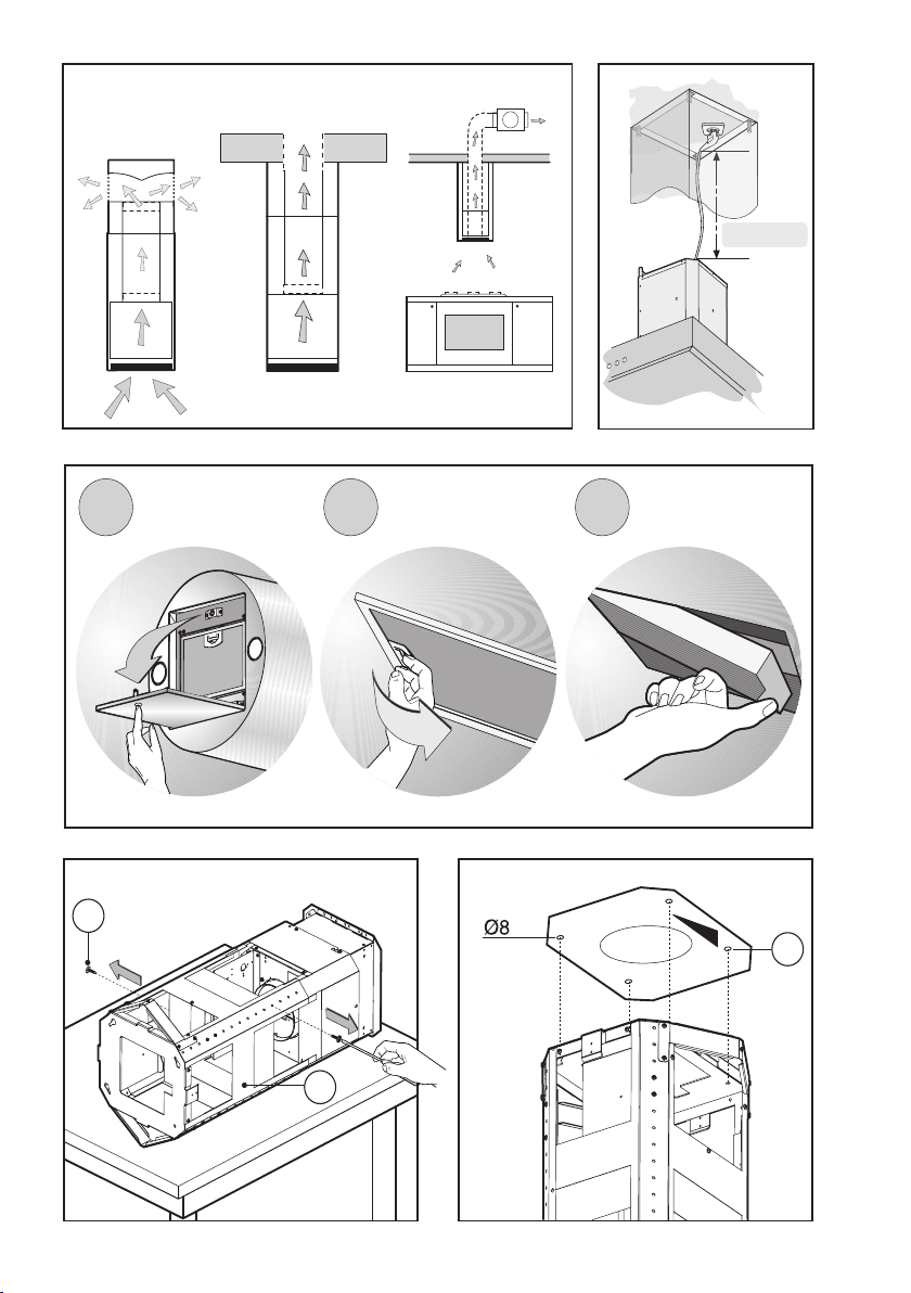
Fig.1
M
max 80 cm
Fig.2
A
a
b
B
c
X
Fig.3
- 3 -
Fig.4
Page 4
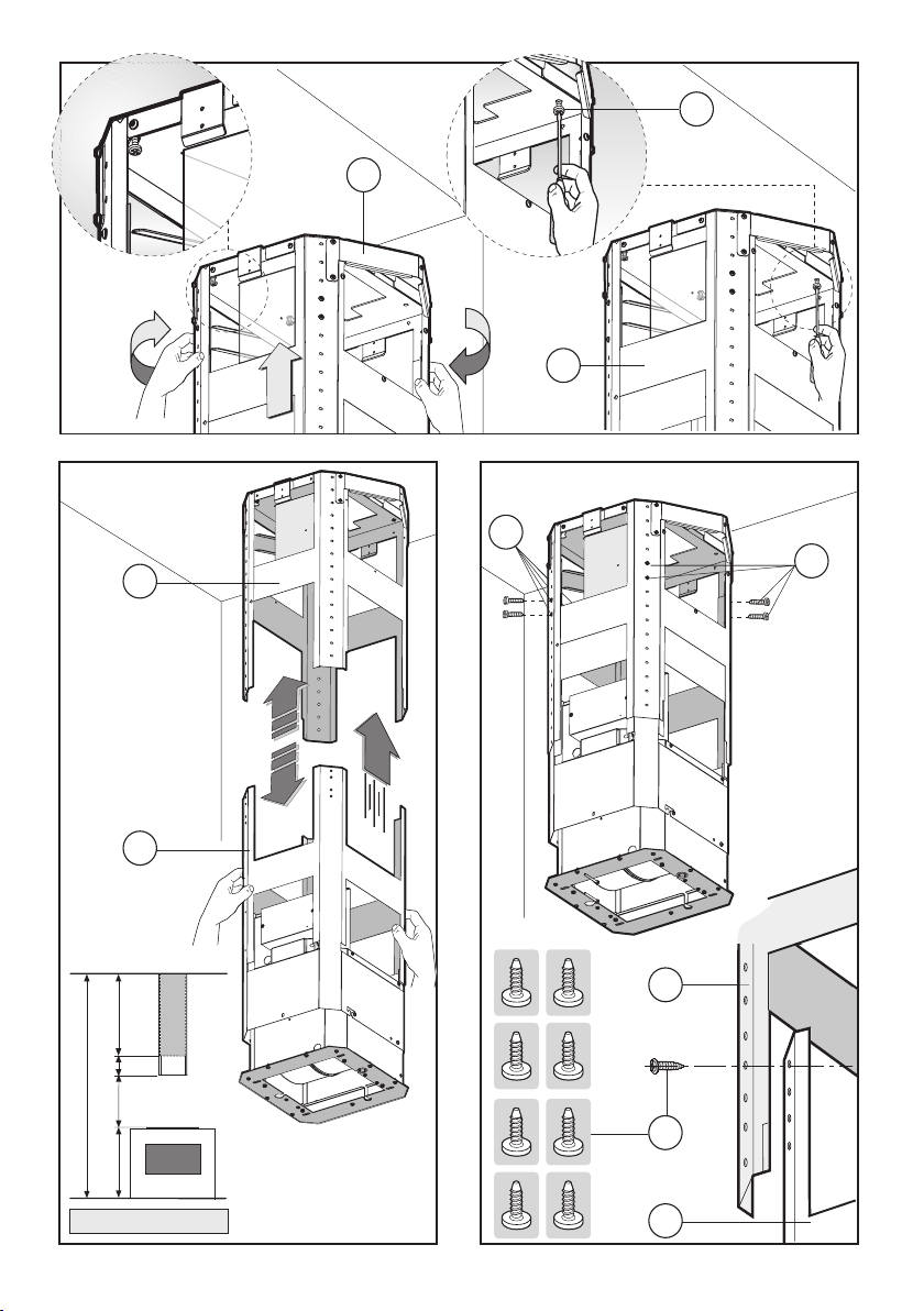
Fig.5
X
B
B
G
G
B
C
X
149
C
650
B
X = C - (149+650+B)
Fig.6 Fig.7
- 4 -
B
G
C
Page 5
M
Fig.8
A
B
H
F
Y
L
Y
X
Y
H
F
Fig.9
Y
L
Fig.10
A
X
Fig.11
- 5 -
A
Page 6
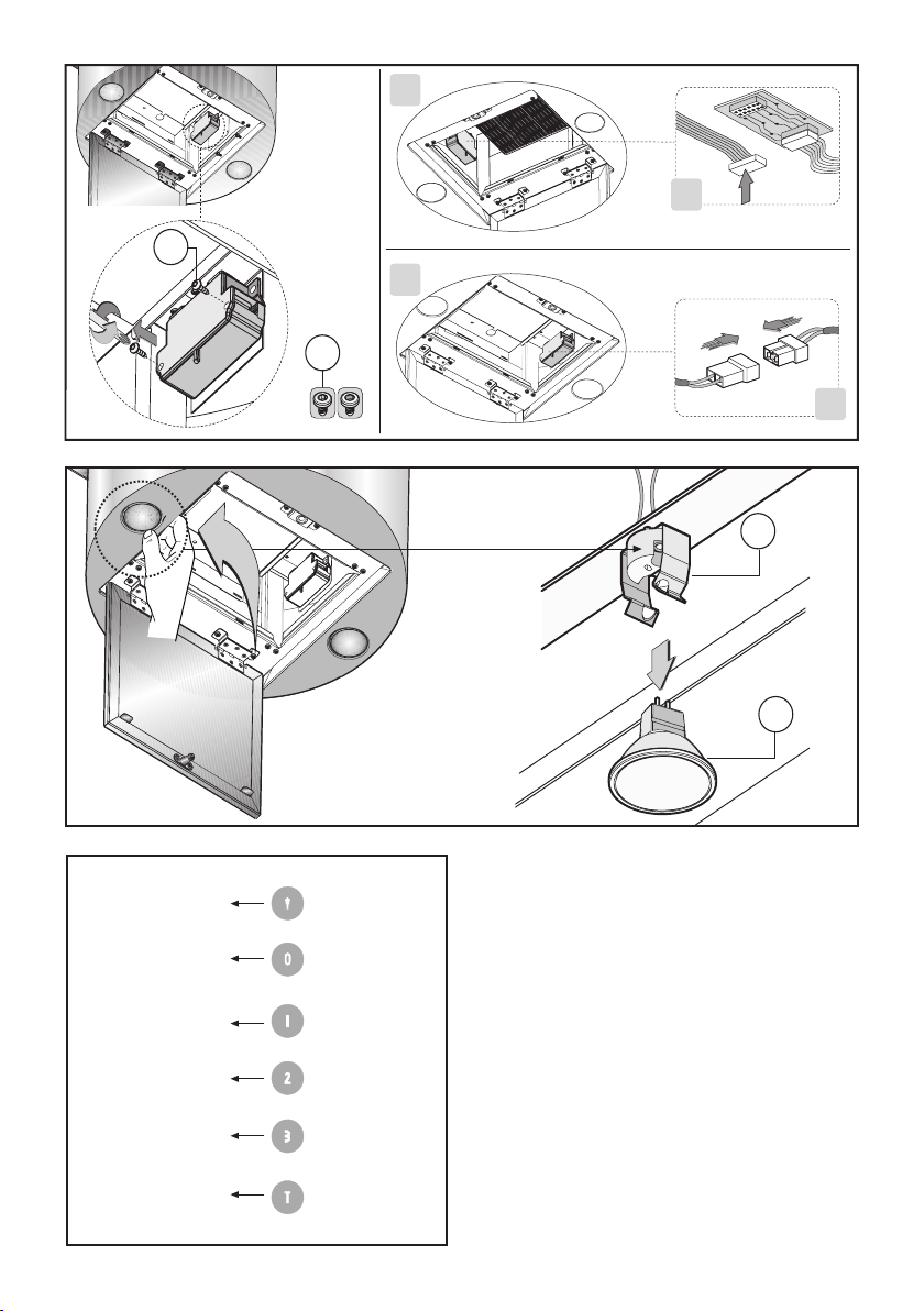
Fig.12
A
A
A
D
B
D
B
B
A
D
Fig.13
Fig.14
A
B
C
D
E
F
- 6 -
Page 7
ENGLISH
GENERAL
Carefully read the following important information regarding installation safety and maintenance. Keep this information booklet accessible for further consultations.
The appliance has been designed for use in the ducting
version (air exhaust to the outside – Fig.1B), filtering
version (air circulation on the inside – Fig.1A) or with
external motor (Fig.1C).
SAFETY PRECAUTION
1. Take care when the cooker hood is operating simulta-
neously with an open fireplace or burner that depend on
the air in the environment and are supplied by other than
electrical energy, as the cooker hood removes the air
from the environment which a burner or fireplace need
for combustion. The negative pressure in the environment
must not exceed 4Pa (4x10⁻⁵ bar). Provide adequate
ventilation in the environment for a safe operation of the
cooker hood.
Follow the local laws applicable for external air evacuation.
Before connecting the model to the electricity network:
- control the data plate (positioned inside the appliance)
to ascertain that the voltage and power correspond to
the network and the socket is suitable. If in doubt ask a
qualified electrician.
- If the power supply cable is damaged, it must be
replaced with another cable or a special assembly, which
may be obtained direct from the manufacturer or from
the Technical Assistance Centre.
2. WARNING !
In certain circumstances electrical appliances may
be a danger hazard.
A) Do not check the status of the filters while the
cooker hood is operating
B) Do not touch bulbs or adjacent areas, during or
straight after prolonged use of the lighting
installation.
C) Flambè cooking is prohibited underneath the
cooker hood
D) Avoid free flame, as it is damaging for the filters
and a fire hazard
E) Constantly check food frying to avoid that the
overheated oil may become a fire hazard
F) Disconnect the electrical plug prior to any maintenance.
G) This appliance is not intended for use by young
children or infirm persons without supervision
H) Young children should be supervised to ensure
they do not play with the appliance
I) There shall be adequate ventilation of the room
when the rangehood is used at the same time as appliances burning gas or other fuels
L) There is a risk of fire if cleaning is not carried out
in accordance with the instructions
This appliance conforms to the European Directive EC/
2002/96, Waste Electrical and Electronic Equipment
(WEEE). By making sure that this appliance is disposed
of in a suitable manner, the user is helping to prevent
potential damage to the environment or to public health.
symbol on the product or on the accompanying
The
paperwork indicates that the appliance should not be
treated as domestic waste, but should be delivered to a
suitable electric and electronic appliance recycling
collection point. Follow local guidelines when disposing
of waste. For more information on the treatment, re-use
and recycling of this product, please contact your local
authority, domestic waste collection service or the shop
where the appliance was purchased.
INSTALLATION INSTRUCTIONS
Assembly and electrical connections must be carried
out by specialised personnel.
• Electric Connection
The appliance has been manufactured as a class II,
therefore no earth cable is necessary.
The connection to the mains is carried out as follows:
BROWN = L line
BLUE = N neutral
If not provided, connect a plug for the electrical load
indicated on the description label. Where a plug is provided, the cooker hood must be installed in order that
the plug is easily accessible.
An omnipolar switch with a minimum opening of 3mm
between contacts, in line with the electrical load and local
standards, must be placed between the appliance and
the network in the case of direct connection to the
electrical network.
• The minimum distance between the support surfaces
of the cooking pots on the cooker top and the lowest
part of the cooker hood must be at least 65 cm.
If a connection tube composed of two parts is used, the
upper part must be placed outside the lower part.
Do not connect the cooker hood exhaust to the same
conductor used to circulate hot air or for evacuating fumes
from other appliances generated by other than an
electrical source.
Before proceeding with the assembly operations, remove
the anti-grease filter(s) (Fig.2b) so that the unit is easier
to handle.
In the case of assembly of the appliance in the suction
version prepare the hole for evacuation of the air.
• We recommend the use of an air exhaust tube which
has the same diameter as the air exhaust outlet hole.
If a pipe with a smaller diameter is used, the efficiency
of the product may be reduced and its operation may
become noisier.
Note!
- When installing this product we recommend you seek
the help of another individual.
- 7 -
GB
Page 8

• Hood assembly
Remove the structure from the packaging and remove
the 2 screws A to separate the upper part from the lower
part (fig.3).
- Position the drilling template on the ceiling, making sure
that the arrow is on the right-hand side in relation to the
appliance controls, as indicated in Figure 4.
Make 4, Ø8 holes in the ceiling and drive in 3 screws
without completely tightening them. Pay attention not to
insert the screw into the hole marked with an X on the
hole template (the screws and expansion plugs must be
suitable for the type of wall).
- Take the upper part of the structure B (fig.5) and insert
the 3 slots onto the 3 screws that are not completely
tightened. Rotate slightly to fit (fig.5) .
Drive in the fourth screw X and tighten the remaining 3
to allow definitive blocking of the upper part of structure
B.
- Take the lower part of the telescopic structure C and
insert it into the upper structure B (fig.6).
Please note:
To avoid scratching the upper duct, first adjust its height
as desired, using the measurements given in (Fig. 6) as
a reference, and then fix it in place using the 8 screws
provided G (Fig. 7).
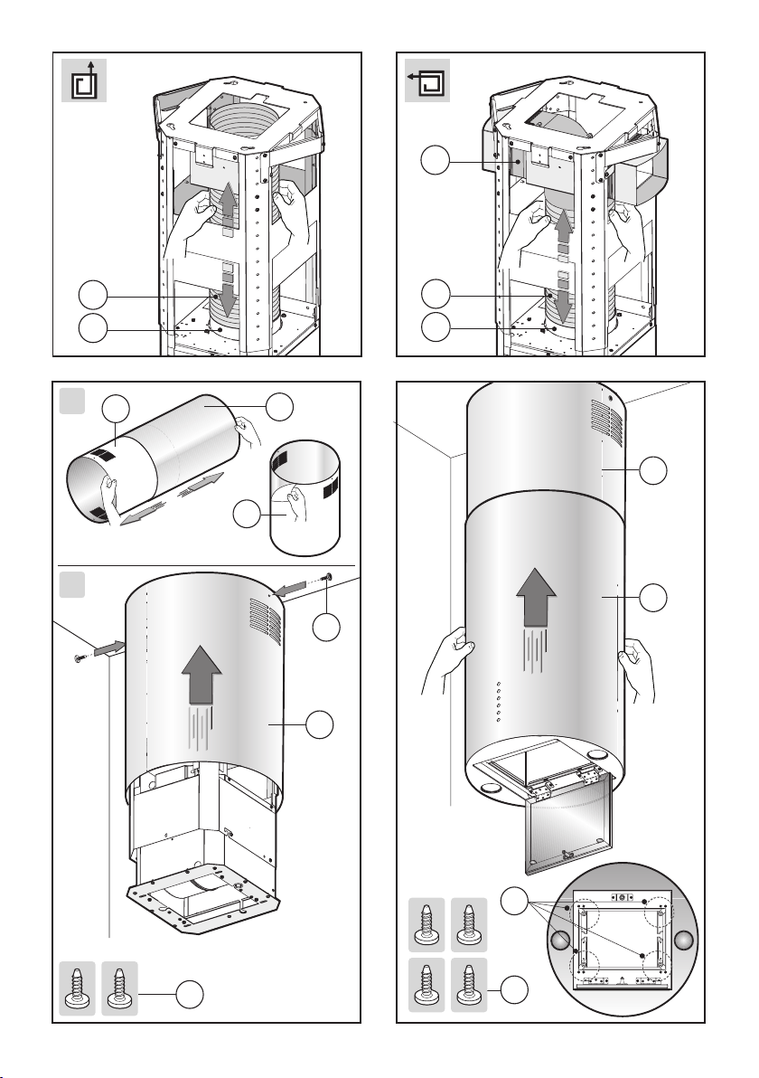
- Extractor hood: connect the flexible hose H (not
supplied) to the air exhaust hole made previously and fix
the hose to the connector flange F (Fig. 8).
- Filter hood: connect the flexible hose H (not supplied)
to the deflector M (Fig. 9).
- Fix the flexible hose H over the connector flange F (Fig.
9).
- The active charcoal filters must be fitted to the extraction
assembly located inside the cooker hood (Fig. 2c).
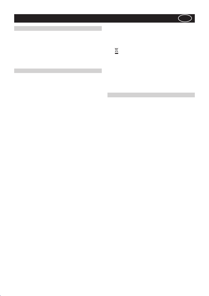
• Before proceeding with the installation process, open
the panel by pressing on the point indicated in Fig. 2a;
this will make the cooker hood easier to handle.
Remove the aluminium panel by pulling the handle as
indicated in Fig. 2b. If the product is supplied with active
charcoal filters, remove them by pulling the lever outwards
as indicated in Fig. 2c.
Take the ducts out of the packaging (Fig. 10A) and separate the upper duct Y from the lower duct L.
Remove the protective materials from the upper duct Y,
as indicated in figure 10A.
- Take the upper duct Y and fix it to the structure using
the 2 screws X (Fig. 10B).
Join the lower part of the cooker hood L to the upper
duct Y until it clicks into place, then secure it in this
position on the lower part of the cooker hood using the 4
screws A as indicated in figure 11.
- Electrical connection
Before performing this connection, loosen the 4 screws
D on the two boxes and open the cover panels (Fig. 12).
- Perform the necessary electrical connections between
the cooker hood body and the motor assembly (Fig. 12
A and B).
USE AND MAINTENANCE
• We recommend that the cooker hood is switched on
before any food is cooked. We also recommend that the
appliance is left running for 15 minutes after the food is
cooked, in order to thoroughly eliminate all contaminated
air.
The effective performance of the cooker hood depends
on constant maintenance; the anti-grease filter and the
active carbon filter both require special attention.
• The anti-grease filter is used to trap any grease particles
suspended in the air, therefore is subject to saturation
(the time it takes for the filter to become saturated
depends on the way in which the appliance is used).
The acrylic filter, which is found resting on the grille,
should be replaced when the text, visible through the
grille, changes colour and the ink spreads; the new filter
should be fitted in such a way that the text can be seen
through the grille from outside the cooker hood.
If the filters do not have any text on them, or if metal
filters or aluminium panel filters are used, they should
be washed every 2 months in order to prevent the risk of
fire. To wash the filters, proceed as follows:
- Remove the filter from the grille and wash it using a
solution of water and neutral liquid detergent, leaving
the dirt to soften.
- Rinse thoroughly with warm water and leave to dry.
The metal filters and/or aluminium panel are also
dishwasher safe. If the filters are made using aluminium,
or if an aluminium panel is used, after a few washes the
colour may change. This does not mean they have to be
replaced.
If the replacement and washing instructions are not
followed, the anti-grease filters may present a fire hazard.
• The active carbon filters are used to purify the air which
is released back into the room. The filters are not
washable or re-usable and must be replaced at least once
every four months. The active carbon filter saturation level
depends on the frequency with which the appliance is
used, the type of cooking performed and the regularity
with which the anti-grease filters are cleaned.
• Remove build-up from the fan and other surfaces of
the cooker hood regularly using a cloth moistened with
denatured alcohol or non-abrasive neutral liquid
detergent.
• The light on the cooker hood is designed for use during
cooking and not for general room illumination. Extended
use of the light reduces the average duration of the bulb.
• Replacing halogen light bulbs (Fig. 13).
To replace the halogen lamps B, from the inside of the
cooker hood press downwards with two fingers as shown
in Fig. 13.
Replace the bulbs with new ones of the same type.
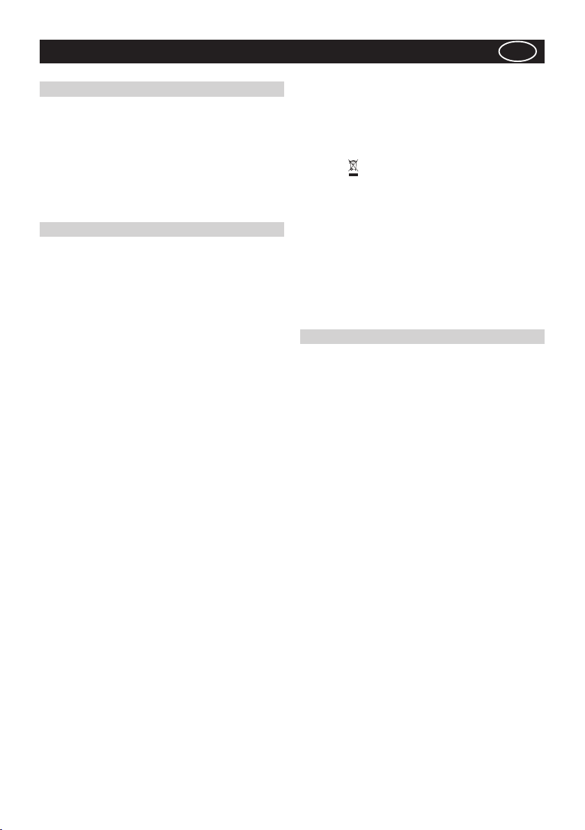
• COMMANDS:
(Fig.14) LUMINOUS the key symbols are explained
below:
A = LIGHT
B = OFF
C = SPEED I
D = SPEED II
E = SPEED III
F = AUTOMATIC STOP TIMER - 15 minutes (*)
• If your appliance does not have the INTENSIVE speed
function, press key E for two seconds and it will be
activated for 10 minutes after which it will return to the
previously set speed. When the function is active the LED
- 8 -
Page 9

flashes. To interrupt it before the 10 minutes have expired
press key E again.
• By pressing key F for two seconds (with the hood
switched off) the “clean air” function is activated. This
function switches the appliance on for ten minutes every
hour at the first speed. As soon as this function is activated the motor starts up at the first speed for ten
minutes, During this time key F and key C must flash at
the same time.
After ten minutes the motor switches off and the LED of
key F remains switched on with a fixed light until the
motor starts up again at the first speed after fifty minutes and keys F and C start to flash again for ten minutes and so on.
By pressing any key for the exclusion of the hood light
the hood will return immediately to its normal functioning
(e.g. if key D is pressed the “clean air” function is deac-
tivated and the motor moves to the 2nd speed straight
away. By pressing key B the function is deactivated).
(*) The “automatic stop timer” delays stopping of the
hood, which will continue functioning for 15 minutes at
the operating speed set at the time this function is
activated.
• Active carbon/grease filter saturation:
- When button A flashes at a frequency of 2 seconds,
the grease filters must be cleaned.
- When button A flashes at a frequency of 0.5 seconds,
the carbon filters must be replaced.
After the clean filter has been replaced, the electronic
memory must be reset by pressing button A for
approximately 5 seconds, until the light on the button
stops flashing.
THE MANUFACTURER DECLINES ALL
RESPONSIBILITY FOR EVENTUAL DAMAGES
CAUSED BY BREACHING THE ABOVE WARNINGS.
- 9 -
Page 10
ČESKY
POLSCPOLSC
CZ
ÚVOD’
Přečtěte si pozorně obsah návodu, protože poskytuje
důležité informace týkající se bezpečné instalace,
používání i údržby zařízení. Uchovejte si návod pro
jakoukoliv budoucí potřebu. Přístroj je určen
k odsávání (odvádění vzduchu ven – obr.1B),
filtrování (recyklace vzduchu v místnosti – obr.1A)
nebo k použití s externě umístěným motorem
(obr.1C).
BEZPECNOSTNÍ OPATRENÍ
1. Vyžaduje se opatrnost, jestliže jsou současně v
činnosti odsávač par a jiný hořák nebo tepelné
zařízení závisející na vzduchu místnosti a napájené
jinou energií než elektrickou, protože odsávač par
spotřebovává vzduch z okolí, který hořák nebo jiné
tepelné zařízení potřebují ke spalování. Negativní tlak
nesmí překročit 4Pa (4x10
provozu je tedy nutná odpovídající ventilace místnosti.
Při odvádění vzduchu do vnějšího prostředí je nutné
se řídit platnými předpisy Vaší země.
Před napojením modelu na elektrickou síť:
- Zkontrolujte tabulku s údaji umístěnou uvnitř
přístroje a ověřte si, že napětí a výkon odpovídají
místní síti a rovněž zásuvka je vhodná. V případě
jakékoliv pochyby se poraďte s kvalifikovaným
elektrikářem.
- Je-li napájecí kabel poškozen, musí být nahrazen
speciálním kabelem nebo sadou, které jsou k
dispozici u výrobce nebo v jeho servisním středisku.
2. UPOZORNĚNÍ !
Za určitých okolností mohou být elektrické
spotřebiče nebezpečné.
A) Neprovádějte kontrolu filtrů se zapnutým
spotřebičem
B) Nedotýkejte se žárovek a prostoru kolem nich
behem užití nebo ihned po dlouhodobém užití
osvetlovacího zarízení.
C) Nedotýkejte se žárovek, bylo-li zařízení déle v
chodu
D) Je zakázáno upravovat pokrmy manipulí
přímého ohně pod fungujícím odsávačem
E) Vyvarujte se volnému plameni, je škodlivý pro
filtry a mohl by způsobit požár
F) Při smažení jídel zajistěte, aby se rozpálený
olej nevznítil
G) Zařízení nebylo navrženo pro použití dětmi
nebo nesvéprávnými osobami bez dozoru.
H) Zkontrolujte, zda si děti nehrají se zařízením.
I) Před provedením jakékoliv údržby vypněte
přístroj z elektrické sítě.
–5
bar). K bezpečnému
Toto zařízení je označeno v souladu s Evropskou
směrnicí 2002/96/ES, Waste Electrical and Electronic
Equipment (WEEE). Tím, že se uživatel ujistí o
správné likvidaci tohoto výrobku, přispívá
k předcházení případným negativním následkům na
životní prostředí a na zdraví.
Symbol
dokumentaci poukazuje na to, že se s tímto výrobkem
nesmí zacházet jako s běžným domovním odpadem,
ale musí se odeslat do vhodné sběrny určené pro
recyklaci elektrických a elektronických zařízení.
Zařízení se musíte zbavit v souladu s místními
předpisy pro likvidaci odpadu.Podrobnější informace
o zacházení s tímto výrobkem, jeho opětovným
použitím a recyklací můžete získat, když se obrátíte
na příslušný místní úřad, sběrnou službu domovního
odpadu nebo obchod, ve kterém jste výrobek
zakoupili.
na výrobku nebo na přiložené
NÁVOD K INSTALACI
Operace spojené s montáží a elektrická napojení
musí být provedeny pouze odborným personálem.
• Elektrické zapojení
Zařízení je vyrobeno v II. třídě, a proto žádný vodič
nesmí být uzemněn.
Napojení k elektrické síti musí být provedeno
následovně:
HNĚDÁ = L vodič
MODRÁ = N neutrální vodič
Na přívodní kabel, pokud ji již neobsahuje, namontujte
zástrčku normalizovanou pro příkon uvedený v
technických charakteristikách výrobku.
V případě přímého zapojení na elektrickou síť je
nezbytné přístroj připojit přes vícepólový spínač s
minimální vzdáleností 3 mm mezi rozpojenými
kontakty, dostatečně dimenzovaný a odpovídající
platným normám.
• Minimální vzdálenost mezi opěrnou plochou
varných nádob na varném zažízení a nejnižším
bodem kuchyňského krytu musí být alespoň 65 cm.
Pokud by došlo k užití spojovací trubky složené ze
dvou nebo více částí, horní část se musí nacházet
vně části spodní. Nenapojujte vývod odsávače na
potrubí, ve kterém proudí teplý vzduch nebo které je
používáno k evakuaci kouře z přístrojů, jež jsou
napájeny jinou energií než elektrickou. Před
zahájením montáže odstraňte protitukový filtr (filtry),
což vám umožní snadnější zacházení s přístrojem.
(Fig.2b).
V případě montáže přístroje ve verzi odsávače je
třeba připravit otvor k evakuaci vzduchu.
• Doporučuje se použít trubku pro odvádění vzduchu se
- 10 -
Page 11
stejným průměrem jako hrdlo výstupu vzduchu.
Použití redukce by mohlo negativně ovlivnit vlastnosti
výrobku a zvýšit hlučnost.
• Montáž na stěnu
- Vyjměte celou strukturu z obalu a odstraňte dva
šrouby A za účelem oddělení horní části od části
spodní (Obr.3).
- Umístěte šablonu pro vrtání otvorů na strop a dbejte
přitom, aby se šipka nacházela na pravé straně
vzhledem k ovládání zařízení, v souladu s obrázkem
4.
Vytvořte 4 otvory Ř8 do stropu a zašroubujte 3 šrouby
bez toho, abyste je zcela utáhli a dávejte pozor,
abyste nezašroubovali šroub do otvoru označeného
X na vrcholu děrování (šrouby a roztahovací špalíčky
musí být vhodné pro typ stěny).
- Uchopte horní část struktury B (Obr.5) a umístěte ji
na 3 šrouby, jež nebyly zcela zašroubovány v souladu
s třemi otvory.
Proveďte malou rotaci za účelem začlenění. (Obr.5)
.
Zašroubujte čtvrtý šroub X a dotáhněte ostatní tři
šrouby, čímž umožníte definitivní upevnění horní části
struktury B.
- Uchopte spodní část teleskopické struktury C a
začleňte ji do vrchní struktury B (obr.6).
Upozornění!
Aby se zabránilo poškrábání horního komínu, je třeba
nejdříve nastavit požadovanou výšku na základě kvót
uvedených na (obr. 6) a zajistit ji prostřednictvím 8
šroubů G z příslušenství (obr. 7).
- Odsávací verze: Pripojte hadici H (nedodává se)
k připravenému otvoru pro odvádění vzduchu a
upevněte hadici k přírubě spojky F (obr. 8).
- Filtrační verze: Připojte hadici H (nedodává se) k
vychylovači M (obr. 9).
- Připevněte hadici H ke spojovací přírubě F (obr.
9).
- Filtry s aktivním uhlím musí být aplikovány na
odsávací jednotce umístěné uvnitř odsavače (obr. 2c).
• Pro usnadnění zacházení s odsavačem před
zahájením úkonů montáže otevřete panel; panel
otevřete zatlačením v místě označeném na obr. 2a.
Sejměte hliníkový panel potažením za rukojeť;
postupujte způsobem znázorněným na obr. 2b. Když
je výrobek dodán s filtry s aktivním uhlím, vyjměte je;
potáhněte páku směrem ven způsobem
znázorněným na obr. 2c.
Uchopte a vyjměte kouřové trubky z obalu (obr. 10A)
a oddělte horní kouřovou trubku Y od spodní L.
Odstraňte ochrannou fólii z horní kouřové trubky Y
způsobem znázorněným na obrázku 10A.
- Uchopte horní kouřovou trubku Y a upevněte ji ke
konstrukci prostřednictvím 2 šroubů X (obr. 10 B).
Spojte spodní část odsavače L s horní kouřovou
trubkou Y až po doraz a poté proveďte definitivní
upevnění ve spodní části odsavače s požitím 4 šroubů
A podle obrázku 11.
- Elektrické zapojení
Před provedením zapojení odšroubujte 4 šrouby D
dvou krabic a otevřete jejich víka (obr. 14).
- Proveďte elektrické zapojení mezi tělesem odsavače
a jednotkou motoru (obr. 14 A a B).
POUŽITÍ A ÚDRŽBA
• Doporučujeme uvést zařízení do činnosti ještě před
zahájením přípravy jakéhokoli jídla. Doporučujeme
ponechat zařízení v činnosti i po dobu 15 minut po
ukončení přípravy jídel, aby byl kompletně odveden
zapáchající vzduch.
Správná činnost odsavače je podmíněna správnou a
nepřetržitou údržbou; zvláštní pozornost je třeba
věnovat protitukovému filtru a filtru s aktivním uhlím.
• Protitukový filtr má za úkol zachycovat mastné
částice nacházející se ve vzduchu, proto je v průběhu
proměnné doby vystaven ucpávání; tato doba závisí
na používání zařízení.
- Aby se předešlo nebezpečí případného požáru,
maximálně každé 2 měsíce je třeba umýt protitukové
filtry; k tomuto účelu je možné použít i myčku nádobí.
- Po několika umytích může dojít je změně barvy. Tato
skutečnost neumožňuje podání reklamace za účelem
jejich výměny.
V případě nedodržení pokynů pro výměnu a mytí
protitukových filtrů se může vyskytnout riziko jejich
zapálení.
• Filtry s aktivním uhlím slouží k čištění vzduchu,
který se znovu vhání do okolního prostředí. Filtry se
nesmí mýt ani regenerovat a musí se měnit
maximálně každé čtyři měsíce. Nasycení aktivního
uhlí závisí na krátkodobém nebo déletrvajícím
používání zařízení, na druhu sporáku a pravidelnosti,
se kterou se provádí vyčištění protitukového filtru.
• Opakovaně čistěte odsavač, zevnitř i zvenčí,
s použitím hadru navlhčeného v denaturovaném lihu
nebo
neabrazivních tekutých čisticích prostředcích.
• Osvětlení je navrženo pro použití během vaření a
ne pro dlouhodobější použití za účelem osvětlení
okolního prostředí. Dlouhodobější použití osvětlení
výrazně snižuje průměrnou životnost žárovek.
• Výměna halogenových žárovek (obr. 13).
Za účelem výměny halogenových žárovek B zevnitř
odsavače zatlačte dvěma prsty směrem dolů,
v souladu s obr. 13.
Žárovky nahraďte novými žárovkami stejného druhu.
POVELY: (Obr.14) Světelné
A = przycisk OŚWIETLENIE
B = przycisk WŁĄCZENIE
C = przycisk PIERWSZA PRĘDKOŚĆ
D = przycisk DRUGA PRĘDKOŚĆ
E = przycisk TRZECIA PRĘDKOŚĆ
F= przycisk REGULATOR CZASOWY
AUTOMATYCZNEGO WYŁĄCZENIA po 15
minutach
- 11 -
Page 12

Pokud je váš prístroj vybven funkcí INTENZÍVNÍ
rychlost, e treba stisknout po dobu aespon 2 s tlacítko
E a rychlost bude aktivována po deset minut a poté
se vrátí do rychlosti, jež byla předem nastavena.
Pokud je funkce aktivní, led bliká. Chcete –li ji přerušit
před vypršením 10 minut, stiskněte znovu klávesu
E.
Po stisknutí tlacítka F po dobu 2 s (kryt je vypnut)
bude aktivována funkce „clean air“. Tato funkce zapne
motor na deset minut každou hodinuna první rychlost.
Jakmile bude tato funkce aktivována, motor bude
uveden do chodu na první rychlost po dobu 10 s,
behem které budou blikat soucasne tlacítka F a C.
Po uplynutí této doby se motor vypne a led tlacítka F
zustane osvetlen až do doby, kdy po 50 minutách
bude znovu motor uveden do chodu na první rychlost
a led F a C znovu zacnou blikat po 10 minut a tak
dále. Po stisknutí jakéhokoliv tlacítka s výjimkou svetel
se kryt okamžite vrátí do svého normálního fungování.
(napr. pokud se stiskne tlacítko D, deaktivuje se
funkce „clean air“ a motor zacne pracovat na druhou
rychlost, stisknutím tlacítka B se tato funkce
deaktivuje.
• Nasycení protitukových filtrů/filtrů s aktivním
uhlím:
- Blikání tlačítka A frekvencí 2 sek. poukazuje na
potřebu umytí protitukových filtrů.
- Blikání tlačítka A frekvencí 0,5 sek. poukazuje na
potřebu výměny uhlíkových filtrů.
Po vložení čistého filtru je třeba vynulovat
elektronickou paměť stisknutím tlačítka A na dobu
přibližně 5 sek., dokud tlačítko nepřestane blikat.
VÝROBCE ODMÍTÁ JAKOUKOLIV
ZODPOVĚDNOST ZA ŠKODY ZPŮSOBENÉ
NEDODRŽENÍM UVEDENÝCH UPOZORNĚNÍ.
- 12 -
Page 13
DANSK
DK
GENERELLE OPLYSNINGER
Læs omhyggeligt indholdet af denne brugsanvisning,
da den giver vigtige oplysninger vedrørende sikkerheden ved installering, brug og vedligeholdelse.
Opbevar brugsanvisningen til senere brug. Apparatet
er udarbejdet til at kunne fungere; udsugende
(udledning af luft til eksterne omgivelser Fig.1B) filtrerende (intern cirkulation af luft Fig.1A) og med
udvendig motor. (Fig.1C).
OPLYSNINGER VEDRØRENDE SIKKERHED
1. Udvis forsigtighed hvis der samtidigt med
emhætten er en varmekilde eller flamme i funktion,
som er afhængig af luften i omgivelserne og forsynet
med energi, der ikke er elektrisk, eftersom emhætten
fjerner den luft fra omgivelserne, som flammen eller
varmekilden har brug for til forbrænding. Det negative
tryk i lokalet må ikke overstige 4 Pa (4x10⁻⁵ bar). For
størst mulig sikkerhed, sørg for en passende
ventilation af rummet. Hvad angår udsugningen til
eksterne omgivelser følg de gældende normer.
Før modellen tilsluttes el-nettet:
- Kontrollèr informationsetiketten (placeret indeni apparatet), for at sikre, at spændingen og styrken er i
overensstemmelse med el-nettet og at
stikkontakterne er egnede. Hvis De er i tvivl, konsultèr
en kvalificeret elektriker.
- Hvis forsyningsledningen er beskadiget, skal den
udskiftes med en ledning eller en særlig samling fra
fabrikanten eller et autoriseret servicecenter.
2. ADVARSEL!
I bestemte situationer kan elektriske hvidevarer
være farlige.
A) Forsøg ikke at kontrollere filtrene mens
emhætten er tændt.
B) Rør ikke ved pærer eller områderne omkring
dem i forbindelse med længere brug af
belysningsanlægget eller straks herefter.
C) Rør ikke ved lamperne efter længerevarende
brug af apparatet.
D) Det er forbudt at flambere under emhætten.
E) Undgå åben flamme da det er skadelig for
filtrene og kan forårsage brand.
F) Hold friturestegning under konstant
overvågning for at undgå, at olien overophedes
og bryder i brand.
G) Apparatet må aldrig bruges af børn eller af
personer, der ikke har de mentale eller fysiske
egenskaber til korrekt brug, uden overvågning.
H) Hold øje med, at børn ikke leger med apparatet.
I) Før man udføre enhver form for vedligeholdelse
skal emhætten være afbrudt fra el-nettet.
Dette apparat er udviklet i overensstemmelse med
det europæiske direktiv 2002/96/EF om affald af
elektrisk og elektronisk udstyr (WEEE). Ved at sikre
sig, at dette produkt bortskaffes på korrekt vis,
bidrager brugeren til at forhindre eventuelle negative
miljømæssige og sundhedsmæssige påvirkninger.
Symbolet
der følger med produktet, angiver, at produktet ikke
skal behandles som husholdningsaffald, men at det
skal bortskaffes på passende vis på
genbrugsstationer til elektriske og elektroniske
apparater. Apparatet skal bortskaffes i
overensstemmelse med de gældende regler for
bortskaffelse af affald. For yderligere oplysninger om
håndtering, genvinding og genbrug af dette produkt,
bedes man kontakte de lokale myndigheder, teknisk
forvaltning eller forretningen, hvor produktet er købt.
på produktet eller på dokumentationen,
INSTRUKTION VED INSTALLERING
Monteringen og udfřrelsen af de elektriske forbindelser, skal udfřres af specialiseret personale.
Den elektriske forbindelse.
Apparatet er udarbejdet i klasse II, derfor skal der
ikke tilsluttes et kabel til jordforbindelsen.
Tilslutning til el-nettet skal udfřres som fřlgende:
BRUN = L Linje
BLĹ = N Neutal
Hvis det ikke allerede findes, montčr da et
standardstik beregnet til den forsyning, som er
angivet pĺ etiketten.Hvis der allerede er et stik, sřrg
da for at det er let tilgćngelig efter installation af
apparatet.
I tilfćlde af en direkte tilslutning til el-nettet er det nřdvendigt at anbringe en flerpolet afbryder med en
afstand mellem kontakterne pĺ minimum 3 mm,
mellem apparatet og nettet. Afbryderen skal passe
til el- forsyningen og vćre i overenstemmelse med
de gćldende normer.
- Minimums distancen mellem kogeoverfladen, mĺlt
fra selve kogepladerne, og den nederste del af
emhhćtten, skal vćre mindst 65 cm.
Hvis der anvendes et forbindelsesrřr bestĺende af to
eller flere dele, skal den řverste del placeres udenpĺ
den nederste. Tilslut ikke udledningen fra emhćtten
med et rřr, hvori der cirkulere varm luft eller som
anvendes til at udlede rřg fra apparater, der ikke
bruger elektrisk energi.
Inden man begynder monteringen fjernes filtret
(Fig.2b) for at gřre hĺndteringen af apparatet lettere.
I de tilfćlde, hvor apparatet skal installeres i en
udsugende version, forberedes ĺbningen til udledning
af luft.
• Det anbefales at anvende en luftudsugningsslange
- 13 -
Page 14

med samme diameter som luftudgangshullet. Hvis
der anvendes en mindre slange, kan det forringe
produktets ydelse og medføre øget støj.
Bemærk!
- Ved installation af dette produkt anbefales det, at
man er to personer.
· Montering af emhætten
-Tag strukturen ud af emballagen og fjern de 2 skruer
A, for at adskille den øverste del fra den nederste
(fig. 3).
- Placér boreskabelonen mod loftet og vær
opmærksom på, at pilen er i højre side i forhold til
apparatets betjeningsanordninger som vist i figur 4.
- Lav 4 huller Ø8 i loftet og skru de 3 skruer i, uden at
stramme dem helt og være opmærksom på, ikke at
placere en skrue i hullet afmærket med et X på
loftsbeslaget (skruer og ravplugs skal være egnede
til mur-typen).
- Tag den øverste del af strukturen B (fig.5) og placèr
den mod de 3 ikke helt fastskruede skruer i
overensstemmelse med de 3 huller.
Drej en lille smule, til den er fastgjort (fig. 5).
Skru den fjerde skrue X i og stram de 3 resterende,
for helt at blokere den øverste del af strukturen B.
- Tag den nederste del af den teleskopisk formet
struktur C og indfør den i den øverste del B (fig.6).
Vær opmærksom!
For at undgå ridser i den øverste afskærmning skal
man justere højden som ønsket, idet der tages hensyn
til de angivne mål i (fig.6). Spænd den fast ved hjælp
af de 8 medfølgende skruer G (fig.7).
- Emhætte med udsugning: Tilslut slangen H (følger
ikke med) til den klargjorte udsugningsåbning, og
fastgør slangen til samleflangen F (fig 8).
- Emhætte med filter: Tilslut slangen H (følger ikke
med) til deflektoren M (fig.9).
- Fastgør slangen H til samleflangen F (Fig. 9).
- De aktive kulfiltre skal monteres på sugeenheden
inden i emhætten (Fig.2c).
• Inden montering og for nemmere håndtering af
emhætten skal man åbne panelet ved at trykke på
de angivne punkter i fig. 2a.
Tag aluminiumspanelet af ved at trække i håndtaget,
som vist i fig. 2b. Hvis produktet er udstyret med aktive
kulfiltre, skal filtrene tages ud ved at trække grebet
udad, som vist i fig. 2c.
Tag afskærmningerne ud af indpakningen (fig.10A),
og skil den øverste del Y fra den nederste L.
Tag beskyttelsesfilmen af den øverste afskærmning
Y, som vist i figur 10A.
- Tag den øverste afskærmning Y, og fastgør den til
strukturen ved hjælp af de 2 skruer X (Fig.10B).
Skub den nederste del af emhætten L op mod den
øverste afskærmning Y, indtil den ikke kan komme
længere, og fortsæt med at fastgøre den nederste
del af emhætten med de 4 skruer A, som vist i figur
11.
- Elektrisk tilslutning
Inden den elektriske tilslutning udføres skal man løse
de 4 skruer D på de to dåser og åbne lågene (Fig.14).
- Foretag de elektriske tilslutninger mellem
emhættelegemet og motorenheden (Fig.14 A og B).
BRUG OG VEDLIGEHOLDELSE
• Det anbefales, at apparatet sættes i funktion, inden
man begynder tilberedningen af madvarer. Det
anbefales, at lade emhætten køre i 15 minutter efter
endt tilberedning, så al mados suges ud.
Korrekt funktion af emhætten afhænger af en korrekt
og jævnlig vedligeholdelse. Man skal især være
opmærksom med at udskifte fedtfilteret og det aktive
kulfilter.
• Fedtfilteret har til opgave at tilbageholde de
fedtpartikler, der findes i luften. Filteret vil derfor blive
tilstoppet med tiden, alt efter hvor ofte emhætten
anvendes.
- For at forebygge risikoen for brand skal man mindst
hver 2 måned rengøre fedtfiltrene; de kan vaskes op
i opvaskemaskine.
- Efter at have rengjort filtrene nogle gange, kan der
opstå misfarvninger. Dette giver ikke ret til reklamation
med henblik på udskiftning.
I tilfælde af manglende overholdelse af anvisningerne
vedrørende udskiftning og rengøring, kan der opstå
brandfare i fedtfiltrene.
• De aktive kulfiltre har til opgave at rense den luft,
der sendes tilbage i lokalet. Filtrene kan ikke vaskes
eller genbruges og skal udskiftes mindst hver fjerde
måned. Mætningen af det aktive kul afhænger af, hvor
ofte emhætten er i brug, komfurets type og hvor ofte
fedtfilteret rengøres.
• Emhætten skal rengøres jævnlige, både indvendigt
og udvendigt, med en klud opvædet i denatureret
alkohol eller et neutralt,
rengøringsmiddel.
• Lyset er beregnet til brug under tilberedning af mad
og ikke til generel oplysning af lokalet.
Længerevarende brug af lyset vil reducere
lyspærernes gennemsnitlige levetid betydeligt.
• Udskiftning af halogenpærer (Fig.13).
For at udskifte halogenpærerne B inden i emhætten,
skal man skubbe pæren nedad med to fingre, som
vist i fig.13.
Udskift pærerne med pærer af samme type.
BETJENING-SENHED:
(Fig.14) LYSENDE er følgende tegnforklaring
gældende:
A = tast for BELYSNING
B = tast for OFF
C = tast for FØRSTE HASTIGHED
D = tast for ANDEN HASTIGHED
E = tast for TREDJE HASTIGHED
F = tast for TIMER AUTOMATISK STOP 15 minutter
ikke slibende
- 14 -
Page 15

Hvis Deres anlæg er udstyret med funktionen
INTENSIV hastighed, skal knappen E holdes
nedtrykket i 2 sekunder hvorved denne aktiveres i
10 minutter hvorefter den vender tilbage til den
forudgående hastighed.
Når funktionen er aktiveret, lyser kontrollampen. For
at afbryde før de 10 minutter er gået, tryk igen på
tasten E.
Ved at trykke på knappen F i 2 sekunder (ved slukket
emhætte) aktiveres funktionen “clean air”. Denne
funktion tænder motoren i 10 minutter pr. time ved
laveste hastighed. Så snart funktionen er igangsat
starter motoren ved første hastighed i 10 minutter,
og under dette forløb skal lamperne ved knap F og
knap C blinke samtidigt. Når tiden er gået standser
motoren og kontrollampen ved knap F forbliver tændt
uden at blinke indtil der er gået endnu 50 minutter,
hvor motoren igen starter ved første hastighed, og
lamperne ved F og C igen begynder at blinke
samtidigt i 10 minutter, og så fremdeles. Ved at trykke
på en hvilken som helst knap bortset fra lysknappen
vender emhætten straks tilbage til den normale
funktion (f.eks. hvis knappen D nedtrykkes bliver funk-
tionen “clean air” afbrudt og motoren går straks i
anden hastighed; ved at trykke knap B afbrydes
funktionen).
• Mætning af fedtfiltre / aktive kulfiltre:
- Når tasten A blinker med 2 sek. mellemrum, skal
fedtfiltrene rengøres.
- Når tasten A blinker med 0,5 sek. mellemrum, skal
kulfiltrene udskiftes.
Når filteret er sat på plads igen, skal den elektroniske
hukommelse nulstilles ved at holde tasten A nede i
ca. 5 sek. indtil den stopper med at blinke.
FABRIKANTEN FRALÆGGER SIG ETHVERT
ANSVAR FOR SKADER FORÅRSAGET AF
MANGLENDE OVERHOLDELSE AF
OVENSTÅENDE ADVARSLER
- 15 -
Page 16

SUOMI
FIN
YLEISTÄ
Lue ohjekirja huolellisesti, sillä se sisältää tärkeätä
tietoa laitteen turvallisesta asennuksesta, käytöstä
ja huollosta. Säilytä ohjekirja tulevaa tarvetta varten.
Laite on suunniteltu toimimaan joko imevänä versiona
(ilman poisto ulos - kuva 1B), suodattavana versiona
(ilman kierrätys sisällä - kuva 1A) tai ulkoisella
moottorilla toimivana versiona (kuva 1C).
TURVAOHJEITA
1. Erityistä huomiota tulee kiinnittää siihen, ettei
liesituuletin ole käytössä samanaikaisesti kuin
tulipesä tai liesi, jotka ovat riippuvaisia huoneilmasta
ja jotka käyttävät jotain muuta energianlähdettä kuin
sähköä. Liesituuletin poistaa huonetilasta ilmaa, jota
tulipesä tai liesi tarvitsevat polttamiseen. Huonetilan
negatiivinen ilmanpaine ei saa ylittää 4Pa (4x10⁻⁵
bar). Huonetilat on siis tuuletettava asianmukaisesti
tuulettimen toiminnan varmistamiseksi. Ulkoista
poistoa koskien tulee noudattaa asianomaisessa
maassa voimassaolevia määräyksiä.
Ennen kuin yhdistät mallin säköverkkoon:
- huomioi sen tunnuskilvessä (löytyy laitteen
sisäpuolelta)olevat tiedot tarkistaen että virran jännite
ja voima vastaavat verkostoa, ja että pistorasia on
sopiva. Jos olet epävarma ota yhteys pätevään
sähkömieheen
- Jos liitäntäjohto on vahingoittunut, se on vaihdettava
laitteen valmistajan tai tämän teknisen
huoltohenkilöstön toimesta uuteen liitosjohtoon tai
sitä vastaavaan.
2. HUOMIO !
Kotitalouskoneet voivat olla vaarallisia tietyissä
olosuhteissa.
A) Suodattimia ei saa yrittää säätää tuulettimen
ollessa käytössä
B) Älä koske lamppuja tai niiden lähiympäristöä
valaisimen ollessa päällä, tai sen pitkään
jatkuneen käytön jälkeen.
C) Lamppuihin ei saa koskea laitteen
pitkäaikaisen käytön jälkeen
D) Tuulettimen alla ei saa valmistaa liekitettyjä
ruokia
E) Tulen polttamista muuten kuin ruoanlaiton yhteydessä tulisi välttää, sillä se vahingoittaa
suodattimia ja voi aiheuttaa tulipalon
F) Valmistettaessa paistettuja ruokia tulee ruokaa
koko ajan vartioida, jotta ylikuumentunut öljy ei
syty palamaan
G) Laitetta ei ole suunniteltu lasten tai
vajaakykyisten käytettäväksi ilman valvontaa.
H) Tarkista, että lapset eivät leiki laitteella.
I) Tuuletin on irrotettava sähköverkosta ennen
huoltotoimenpiteiden aloittamista
Tämä laite on merkitty EU:n Waste Electrical and
Electronic Equipment (WEEE) -direktiivin 20002/96/
EC mukaisesti. Käyttäjä osallistuu mahdollisten
terveydelle ja ympäristölle haitallisten seurausten
ehkäisemiseen hävittäessään laitteen
asianmukaisella tavalla.
Laitteen pakkauksessa mukana oleviin asiakirjoihin
merkitty
talousjätteisiin, vaan se on varta vasten toimitettava
sähkö- ja elektroniikkalaiteromun keräyspisteeseen
kierrätystä varten.Hävitä laite noudattamalla
paikkakuntasi jätehuoltoa koskevia säädöksiä.
Lisätietoja tämän laitteen keräyksestä, käsittelystä
ja kierrätyksestä ota yhteys paikkakuntasi
jätehuoltoon, talousjätteiden keräyspisteseen tai
liikkeeseen josta laite on hankittu.
-merkki osoittaa ettei kyseinen laite kuulu
ASENNUSOHJEET
Asennus ja sähköliitäntä on suoritettava siihen pätevän erikoishenkilöstön toimesta.
• Sähköinen liitäntä
Laite on rakennettu II-luokassa, eivätkä kaapelit sen
vuoksi saa olla liitettyjä maajohtoon. Liitännät sähköverkkoon on tehtävä seuraavalla tavalla:
RUSKEA = L linja
SININEN = N neutraali
Tarvittaessa tulee kaapeliin asentaa standardipistoke,
joka kestää tuoteselosteessa mainitun kuormituksen.
Jos laitteessa on pistoke, kupu on asennettava siten,
että pistokkeeseen pääsee käsiksi.
Liitettäessä suoraan sähköverkkoon täytyy laitteen
ja verkon väliin laittaa moninapainen virrankatkaisija,
jossa kontaktien minimiväli on 3 mm ja on mitoitettu
kuormituksen mukaan ja joka on voimassaolevien
määräysten mukainen.
• Keittopinnan kattilankannattimien ja hellakuvun
minimietäisyyden on oltava vähintään 65 cm.
Mikäli joudutaan käyttämään kaksi- tai
useampiosaista liitosputkea, on ylemmän osan oltava
alemman ulkopuolella. Poistoilmaa ei saa johtaa
kuumailmahormiin tai hormiin, jota käytetään savun
poistamiseen laitteista, jotka toimivat jollakin muulla
energianlähteellä kuin sähköllä. Ennen kuin alat koota
laitetta, irrota rasvasuodatin/-suodattimet (kuva 2b)
näin laitetta on helpompi käsitellä.
Jos asennetaan imevä hellakupu on ensin tehtävä
ilmanpoistoaukko.
• Suositellaan käyttämään ilmanpoistoputkea, jonka
halkaisija vastaa ilman ulostuloaukon mittoja.
- 16 -
Page 17

Pienentävien sovituskappaleiden käyttö voi alentaa
tuotteen toimintatulosta ja lisätä meluisuutta.
Huomaa!
- Tämän tuotteen asentaminen suositellaan
tehtäväksi toisen henkilön avustuksella.
·Hellakuvun asennus
-Ota laite esille sitä suojaavasta pakkausmateriaalista
ja poista kaksi ruuvia A erottaaksesi ylä- ja -ala-osat
toisistaan (kuva 2).
- Aseta reikäsapluuna kattoon ollen tarkkana, että
nuoli on oikealla verrattuna laitteen ohjaimiin kuten
osoitettu kuvassa 4.
Tee nyt 4 Ø8 reikää ja kiinnitä sitten 3 ruuvia niin
etteivät ne ole aivan tiukalla, ja huomioiden että
kohdannusmaskin X .llä merkitty reikä jää vapaaksi
(holkkien ja ruuvien on oltava asianmukaiset seinän
materiaaliin nähden).
-Ota rakenteen B yläosa (kuva 5) ja aseta se kolmen
hiukan löysän ruuvin kohdalle varoen että rakenteen
kolme ruuvinläpeä kohdittuvat täydellisesti.
Kierrä sitten rakennetta siten että se lomittuu kiinni
(kuva 5).
Kiinnitä nyt neljäs ruuvi X ja kiristä kolme muuta
ruuvia niin että rakenteen B yläosa on lopullisesti
kiinnitetty.
-Ota sisäkkäin asennettavan rakenteen C alaosa ja
asenna se rakenteeseen B (kuva 6).
Varoitus!
Jotta vältetään ylemmän hormin naarmuuntuminen,
säädä ensin haluttu korkeus noudattaen mittoja, jotka
on osoitettu (kuva 6) ja lukitse toimitetuilla 8 ruuvilla
G (kuva 7).
- Imevä versio: liitä letku H (ei toimitettu)
esivalmisteltuun ilman poistoaukkoon ja kiinnitä letku
liitäntälaippaan F (kuva 8).
- Suodattava versio: liitä letku H (ei toimituksen
mukana) kääntökouruun M (kuva 9).
- Kiinnitä letku H liitäntälaippaan F (Kuva 9).
- Aktiivihiilisuodattimet tulee asentaa imuyksikköön,
joka sijaitsee liesituulettimen sisällä (Kuva 2c).
• Ennen asennustoimenpiteiden suorittamista,
liesituulettimen käsittelemiseksi helpommin, avaa
paneeli painaen kuvassa 2a osoitettuun kohtaan.
Poista alumiinipaneeli vetäen kahvasta kuten
osoitettu kuvassa 2b. Jos tuote on toimitettu
aktiivihiilisuodattimien kanssa, poista ne vetäen
ulospäin vipua kuten osoitettu kuvassa 2c.
Ota hormit pakkauksesta (kuva 10A) ja irrota ylähormi
Y alahormista L.
Poista suojus ylähormista Y kuten osoitettu kuvassa
10A.
- Ota ylähormi Y ja kiinnitä se kehikkoon 2 ruuvilla X
(Kuva 10B).
Yhdistä liesituulettimen alaosa L ylähormin Y kanssa
pysäytyspisteeseen saakka, sitten suorita
liesituulettimen alaosan lopullinen kiinnitys käyttäen
4 ruuvia A kuten osoitettu kuvassa 11.
- Sähköliitäntä
Ennen liitännän suorittamista, ruuvaa auki 4 ruuvia
D kahdesta laatikosta ja avaa kannet (Kuva 14).
- Suorita sähköliitännät liesituulettimen rungon ja
moottoriyksikön välillä (Kuva 14 A ja B).
KÄYTTÖ JA HUOLTO
• Suositellaan käynnistämään laite ennen minkä
tahansa ruuan kypsennyksen aloittamista. On
suositeltavaa antaa laitteen toimia vielä 15 minuuttia
käytön jälkeen, jotta ruoanvalmistuksesta aiheutuneet
käryt saadaan kokonaan pois huonetilasta.
Liesituulettimen hyvä toiminta riippuu oikeasta ja
säännöllisestä huollosta; erityistä huomiota tulee
kiinnittää rasvasuodattimeen ja
aktiivihiilisuodattimeen.
• Rasvasuodattimen tehtävänä on pidättää ilmassa
leijuvat rasvahiukkaset ja siksi se on altis
tukkeutumaan ajanjaksossa, jonka pituus vaihtelee
laitteen käytön mukaan.
- Tulipalovaaran estämiseksi korkeintaan joka 2
kuukauden välein tulee pestä rasvasuodattimet, jotka
voidaan pestä myös astianpesukoneessa.
- Muutaman pesukerran jälkeen voi tapahtua
värimuutoksia. Tämä tosiasia ei anna oikeutta vaatia
niiden vaihtamista.
Mikäli ei noudateta vaihtamista tai pesemistä
koskevia ohjeita, rasvasuodattimien tulipalovaara
lisääntyy.
• Aktiivihiilisuodattimia käytetään puhdistamaan
ilma, joka palautetaan huonetilaan. Suodattimia ei voi
pestä tai käyttää uudelleen ja ne tulee vaihtaa
vähintään joka neljäs kuukausi. Aktiivihiilen
kyllästyminen riippuu laitteen käyttöajan pituudesta,
ruuanvalmistustavoista ja säännöllisyydestä, jolla
suoritetaan rasvasuodattimen puhdistus.
• Puhdista liesituuletin säännöllisesti sekä sisältä että
ulkoa käyttäen riepua, joka on kostutettu
denaturoidulla alkoholilla tai nestemäisillä
neutraaleilla
• Valaistuslaitteisto on suunniteltu käytettäväksi
ruokien kypsennyksen aikana eikä pitkäaikaiseen
ympäristön yleiseen valaisuun. Valaistuksen
pitkäaikainen käyttö vähentää huomattavasti
lamppujen keskimääräistä käyttöikää.
• Halogeenilamppujen vaihtaminen (Kuva 13).
Halogeenilamppujen B vaihtamiseksi liesituulettimen
sisällä työnnä alaspäin kahdella sormella kuten
osoitettu kuvassa 13.
Vaihda tilalle vastaavan tyyppiset lamput.
OHJAIMET: (kuva14) VALOLLA VARUSTETUT
A = Valaistuksen painike
B = OFF
C = ensimmäisen nopeuden painike
D = toisen nopeuden painike
E = kolmannen nopeuden painike
F = Automaattiajastin (15 min.)
- 17 -
ei-hankaavilla pesuaineilla.
Page 18

Jos laitteesi on varustettu INTENSIIVI nopeudella,
pidä painettuna n. 2 sekuntia näppäintä E jolloin se
käynnistyy kymmeneksi minuutiksi, jonka jälkeen
palaa ennaltakäsin ohjelmoituun nopeuteen.
Kun toiminta on käynnissä valomerkki välkkyy. Jos
haluat katkaista toiminnan ennenkuin 10 min. on
kulunut painalla uudelleen näppäintä E.
Jos painallat näppäintä F n.2 sek. (tuulettimen ollessa
pois päältä), käynnistät tominnon “clean air”. “Clean
air” käynnistää tuulettimen kymmeneksi minuutiksi
tunnin väliajoin alimmalla kierrosnopeudella. Jos
valitset tämän toimintamuodon laite käynnistyy
kymmeneksi minuutiksi joiden aikana välkehtivät
näppäinten F ja C. n valomerkit. Kymmenen minuutin
jakson päätyttyä moottori pysähtyy ja vain näppäimen
F valomerkki jää päälle kunnes 50.nen minuutin
kuluttua moottori käynnistyy uudelleen ja näppäimien
F ja C valomerkit välkehtivät jne. Valiten minkä
tahansa muun näppäimen – valaisinta lukuunottamatta – tuuletin palautuu heti normaaliin käyttöön (esim.
jos painat näppäintä D “clean air” poistuu käytöstä
ja tuuletin pyörii kakkosnopeudella; painaltaen
näppäintä B toiminta poistuu käytöstä).
• Rasva-/aktiivihiilisuodattimien täyttyminen:
- Kun näppäin A vilkkuu 2 sekunnin välein,
rasvasuodattimet tulee pestä.
- Kun näppäin A vilkkuu 0,5 sekunnin välein,
aktiivihiilisuodattimet tulee vaihtaa.
Kun puhdas suodatin on liitetty, tulee elektroninen
muisti nollata painaen painiketta A noin 5 sekunnin
ajan, kunnes se lakkaa vilkkumasta.
LAITTEEN VALMISTAJA EI OLE VASTUUSSA VAHINGOISTA, JOTKA OVAT AIHEUTUNEET YLLÄMAINITTUJEN
OHJEIDEN LAIMINLYÖNNISTÄ.
- 18 -
Page 19
EΛΛHNIKA
ΓΕΝΙΚΑ
∆ιαβάστε προσεκτικά το περιεχµενο των οδηγιών,
διτι παρέχει σηµαντικέσ υποδείξεισ που αφορούν
την ασφάλεια τησ εγκατάστασησ τησ χρήσησ και τησ
συντήρησησ. Φυλάξτε το φυλλάδιο για ενδεχµενεσ
συµβουλέσ. Η συσκευή σχεδιάστηκε για χρήση σε
έκδοση απορρφησησ (εκκένωση αέρα προσ τα έξω
– Εικ. 1Β) ή φιλτραρίσµατοσ (ανακυκλοφορία αέρα
στο εσωτερικ – Εικ. 1Α) ή µε εξωτερικ κινητήρα
(Εικ.1C).
ΥΠΟΔΕΙΞΕΙΣ ΑΣΦΑΛΕΙΑΣ
1. Προσοχή σε περίπτωση που λειτουργούν
ταυτχρονα απορροφητήρασ απορρφησησ και
καυστήρασ ή µια εστία που εξαρτούνται απ τον
αέρα του περιβάλλοντοσ και τροφοδοτούνται απ
ενέργεια χι ηλεκτρική διτι ο απορροφητήρασ
απορροφντασ αφαιρεί απ το περιβάλλον τον
αέρα που έχουν ανάγκη για την καύση ο
καυστήρασ ή η εστία. Η αρνητική πίεση στο χώρο
δεν πρέπει να ξεπερνά τα 4PA (4x10⁻⁵bar). Για
σίγουρη ασφαλέσ λειτουργία του απορροφητήρα,
οφείλεται να υπάρχει κατάλληλοσ αερισµσ στο
χώρο. Για την εξωτερική εκκένωση ακολούθησε
τισ ισχύοντεσ προδιαγραφέσ τησ χώρασ.
Πρίν συνδέσετε το μοντέλο στο ηλεκτρικ"
δίκτυο:
- Ελέγξτε την πινακίδα στοιχείων (που βρίσκεται
στο εσωτερικ τησ συσκευήσ) για να βεβαιωθείτε
τι η τάση και η ισχύσ τησ συσκευήσ αντιστοιχούν
στο ηλεκτρικ σασ δίκιο καθώσ και για την
καταλληλτητα του ηλεκτρικού βύσµατοσ. Σε
περίπτωση δυσκολιών επικοινωνήστε µε έναν
ειδικευµένο ηλεκτρολγο
- Αν το καλώδιο τροφοδοσίασ είναι χαλασµένο,
πρέπει να αντικατασταθεί απ ένα καλώδιο ή ένα
ειδικ σύστηµα, διαθέσιµo απ τον κατασκευαστή
ή την υπηρεσία του τεχνικήσ υποστήριξησ.
2. ΠΡΟΣΟΧΗ !
Σε ορισμένες περιπτώσεις οι ηλεκτρικές οικιακές
συσκευές μπορεί να είναι επικίνδυνες!
Α) Μην ελέγχετε ποτέ τα φίλτρα "ταν ο
απορροφητήρας είναι σε λειτουργία.
B) Μην ακουμπάτε τις λάμπες και τις γύρο
περιοχές, κατά την διάρκεια και μετά την
παρατεταμένη χρήση της εγκατάστασης φωτισμού.
C) Μην αγγίζετε την λάμπα μετά απ"
παρατεταμένη χρήση της συσκευής
D) Απαγορεύεται το μαγείρεμα φαγητών με
φλ"γες κάτω απ" τον απορροφητήρα
E) Να αποφεύγονται ανοιχτές φλ"γες γιατί
καταστρέφονται τα φίλτρα και υπάρχει κίνδυνος
πυρκαγιάς
F) Ελέγχετε τα φαγητά κατά το τηγάνισμα για
την αποφυγή υπερθέρμανσης του λαδιού.
G) H συσκευή δεν σχεδιάστηκε για να
χρησιμοποιείται απ" παιδιά ή μη ικανά άτομα
χωρίς επιτήρηση.
H) Ελέγχετε να μην παίζουν παιδιά με τη
συσκευή.
I ) Σε περίπτωση που υποστεί βλάβη το καλώδιο
του απορροφητήρα, θα πρέπει αυτ" να
επισκευαστεί απ" σέρβις εξουσιοδοτημένο απ"
τον προμηθευτή δι"τι απαιτούνται ειδικά εργαλεία.
L) Πριν απ" οποιαδήποτε επισκευή βγάζετε
πρώτα οπωσδήποτε το καλώδιο απ" την πρίζα.
Η συσκευή αυτή είναι χαρακτηρισµένη σύµφωνα
µε την Ευρωπαϊκή Οδηγία 2002/96/EC, Waste
Electrical and Electronic Equipment (WEEE). Ο
χρήστησ µε το να διαθέτει το προϊν αυτ ωσ
απρριµµα µε τον ενδεδειγµένο τρπο συµβάλει
στην αποφυγή αρνητικών συνεπειών για το
περιβάλλον και την υγεία.
Το σύµβολο
που το συνοδεύει δείχνει τι το προϊν αυτ δεν
πρέπει να αντιµετωπίζεται ωσ απρριµµα οικιακ
αλλά πρέπει να παραδίνεται σε κατάλληλα σηµεία
συλλογήσ για την ανακύκλωση ηλεκτρικών και
ηλεκτρονικών συσκευών.
∆ιαθέστε το ωσ απρριµµα τηρώντασ τουσ κατά
τπουσ κανονισµούσ για τη διάθεση των
απορριµµάτων.
Για περαιτέρω πληροφορίεσ για τη µεταχείριση,
την ανάκτηση και την ανακύκλωση του προϊντοσ
αυτού, επικοινωνήστε µε το αρµδιο τοπικ
γραφείο, την υπηρεσία συλλογήσ οικιακών
απορριµµάτων ή το κατάστηµα απ το οποίο
αγοράσατε το προϊν αυτ.
στο προϊν ή στην τεκµηρίωση
ΟΔΗΓΙΕΣ ΕΓΚΑΤΑΣΤΑΣΗΣ
Οι διαδικασίες τοποθέτησης και ηλεκτρικής
σύνδεσης πρέπει να γίνονται απ" ειδικευμένο
προσωπικ".
• Ηλεκτρική σύνδεση
Η συσκευή ανήκει στο τύπο ΙΙ, που σηµαίνει πωσ
κανένα καλώδιο δεν πρέπει να συνεθεί µε την
γείωση.
Η σύνδεση στο δίκτυο θα πρέπει να γίνει ωσ εξήσ:
ΚΑΦΕ: γραµµή L
ΜΠΛΕ: N ουδέτερη γραµµή
Αν δεν υπάρχει ήδη ένα φισ µοντάρετε στο
καλώδιο ένα φισ προσαρµοσµένο στο ηλεκτρικ
φορτίο που αναφέρεται στην χαρακτηριστική
ετικέτα.
Αν υπάρχει ήδη, ττε ο απορροφητήρασ θα
πρέπει να µονταριστεί, έτσι ώστε το φισ να είναι
σε προσιτ για τη χρήση σηµείο.
- 19 -
GR
Page 20

Σε περίπτωση άµεσησ σύνδεσησ µε το ηλεκτρικ
δίκτυο είναι αναγκαίο να παρεµβληθεί µεταξύ τησ
συσκευήσ και του ηλεκτρικού δικτύου ένασ
πολυπολικσ διακπτησ µε ελάχιστο άνοιγµα µεταξύ
των επαφών 3mm προσαρµοσµένο στο ηλεκτρικ
φορτίο και να συµφωνεί µε τα ισχύοντα πρτυπα.
• Η ελάχιστη απσταση απ την επιφάνεια
στήριξησ των συσκευών µαγειρέµατοσ στισ
εστίεσ και το χαµηλτερο τµήµα του
απορροφητήρα τησ κουζίνασ πρέπει να είναι ίση
µε τουλάχιστον 65 εκ.
Σε περίπτωση που χρησιµοποιηθεί σωλήνασ
σύνδεσησ το οποίο αποτελείται απ δύο ή
περισστερα κοµµάτια, θα πρέπει το πάνω µέροσ
να περαστεί πάνω απ το κάτω µέροσ. Σε καµία
περίπτωση δεν πέπει ο σωλήνασ απορρφησησ
να συνδεθεί µε σωλήνα, ο οποίοσ χρησιµοποιείτε
για εκκένωση καπνού συσκευών που
τροφοδοτούνται απ ενέργεια χι ηλεκτρική.
Πριν προχωρήσετε στισ διεργασίεσ
συναρµολγησησ, για ευκολτερο χειρισµ τησ
συσκευήσ αποσυνδέστε το φίλτρο/-α
συγκράτησησ λιπαρών (Εικ.2b).
- Στην περίπτωση συναρµολγησησ τησ συσκευήσ
στην έκδοση για απορρφηση τοποθετήστε την
οπή εξαγωγήσ αέρα.
• Συνιστάται η χρήση ενσ σωλήνα εκκένωσησ
αέρα ίδιασ διαµέτρου µε το στµιο εξδου αέρα.
Η χρήση προσαρµοστικού θα µπορούσε να
µειώσει τισ επιδσεισ του προϊντοσ και να
αυξήσει τη θορυβτητα.
Σημείωση!
- Για την εγκατάσταση του προϊντοσ αυτού
προτείνεται η βοήθεια ενσ δεύτερου ατµου.
• Συναρμολ"γηση του απορροφητήρα
- Αφαιρέστε την συσκευή απ την συσκευασία τησ
και ξεβιδώστε τισ δύο βίδεσ Α για να
αποσυναρµολογήσετε το άνω απ το κάτω τµήµα
τησ (Σχ.2).
Τοποθετήστε το πρτυπο διάτρησησ στην οροφή
προσέχοντασ τι το βέλοσ να είναι στο δεξί
πλευρ, σε σχέση µε τα χειριστήρια τησ
συσκευήσ, πωσ φαίνεται στην εικνα 4.
Ανοίξτε τισ 4 τρύπεσ R8 στο ταβάνι και βιδώστε
3 βίδεσ χωρίσ να τισ σφίξετε τελείωσ και µε
προσοχή ώστε να µην βιδώσετε την βίδα στην
οπή µε το σηµάδι a X sulla dima di foratura (οι
βίδεσ και τα αντίστοιχα ούπα πρέπει να είναι
κατάλληλα για την τυπολογία του τοίχου).
- Πάρτε το πάνω µέροσ τησ συσκευήσ B (Σχ.5)
και περάστε το στισ 3 µη σφιγµένεσ βίδεσ στο
σηµείο των 3ων οπών.
Στρίψτε ελαφρά µέχρι να κουµπώσει (Σχ.5) .
Βιδώστε την τέταρτη βίδα X και τραβήξτε τισ
άλλεσ 3 για να µπλοκαριστεί το πάνω τµήµα τησ
συσκευήσ B
- Πάρτε το κάτω τµήµα τησ τηλεσκοπικήσ δοµήσ
C και εφαρµστε την στο άνω τµήµα B (Σχ.6).
Προσοχή!
Για την αποτροπή ξυσιµάτων στον επάνω
απαγωγ πρέπει να ρυθµίσετε το επιθυµητ ύψοσ
έχοντασ ωσ αναφορά τα µεγέθη που αναφέρονται
στην (εικ.6) και ασφαλίστε µε τισ 8 βίδεσ G που
σασ παρέχονται (εικ.7).
- Έκδοση απορρ"φησης: συνδέστε τον εύκαµπτο
σωλήνα H (δεν παρέχεται) στην έτοιµη οπή
εκκένωσησ αέρα και στερεώστε το σωλήνα στη
φλάντζα του ρακρ F (εικ. 8).
- Έκδοση φιλτραρίσματος: συνδέστε τον
εύκαµπτο σωλήνα H (δεν παρέχεται) στον
εκτροπέα M (εικ.9).
- Στερεώστε τον εύκαµπτο σωλήνα H στη
Φλάντζα του ρακρ F (Εικ. 9).
- Τα φίλτρα ενεργού άνθρακα πρέπει να
εφαρµζονται στη µονάδα απορρφησησ στο
εσωτερικ του απορροφητήρα (Εικ. 2c)..
• Πριν προχωρήσετε µε τη διεργασία
συναρµολγησησ, για ευκολτερο χειρισµ του
απορροφητήρα, ανοίξτε το πάνελ πιέζοντασ στο
σηµείο που υποδεικνύεται στην εικ. 2a.
Βγάλτε το πάνελ αλουµινίου τραβώντασ τη λαβή
πωσ δείχνει η εικ. 2b. Αν το προϊν παρέχεται
µε φίλτρα ενεργού άνθρακα, αφαιρέστε τα
τραβώντασ προσ τα έξω το µοχλ, πωσ δείχνει
η εικ. 2c.
Πάρτε τισ καπνοδχουσ απ τη συσκευασία (εικ.
10Α) και διαχωρίστε την επάνω καπνοδχο Υ απ
την κάτω L.
Αφαιρέστε το προστατευτικ τησ επάνω
καπνοδχου Υ πωσ δείχνει η εικνα 10Α.
- Πάρτε την επάνω καπνοδχο Υ και στερεώστε
τη στη δοµή µέσω των 2 βιδών Χ (Εικ.10Β).
Συζεύξτε το κάτω τµήµα του απορροφητήρα L
µε την επάνω καπνοδχο Υ µέχρι το σηµείο στοπ,
µετά προχωρήστε στην οριστική στερέωση στο
κάτω τµήµα του απορροφητήρα
χρησιµοποιώντασ τισ 4 βίδεσ A πωσ δείχνει η
εικνα 11.
- Ηλεκτρική σύνδεση
Πριν διενεργήσετε τη σύνδεση, ξεβιδώστε τισ 4
βίδεσ D των δύο κουτιών και ανοίξτε τα καπάκια
(Εικ.14)
- Πραγµατοποιήστε τισ ηλεκτρικέσ συνδέσεισ
µεταξύ του σώµατοσ του απορροφητήρα και
τησ µονάδασ κινητήρα (Εικ. 14Α και Β).
ΧΡΗΣΗ ΚΑΙ ΣΥΝΤΗΡΗΣΗ
• Συνιστάται να θέτετε σε λειτουργία τη συσκευή
πριν προχωρήσετε στο µαγείρεµα κάποιου
τροφίµου. Συστήνεται να αφήνετε τη συσκευή να
λειτουργεί για 15 λεπτά αφού τελειώσετε το
µαγείρεµα των τροφίµων, για πλήρη εκκένωση
του µολυσµένου αέρα.
Η καλή λειτουργία του απορροφητήρα εξαρτάται
- 20 -
Page 21
απ τη σωστή και συνεχή συντήρηση. Ιδιαίτερη
προσοχή πρέπει να δοθεί στο φίλτρο
συγκράτησησ λίπουσ και στο φίλτρο ενεργού
άνθρακα.
• Το φίλτρο συγκράτησης λίπους έχει ωσ σκοπ
τη συγκράτηση των λιπαρών σωµατιδίων που
αιωρούνται στον αέρα, συνεπώσ υπκειται σε
έµφραξη σε χρονικά διαστήµατα που ποικίλουν
ανάλογα µε τη χρήση τησ συσκευήσ.
- Για την πρληψη του κινδύνου ενδεχµενων
πυρκαγιών, το πολύ κάθε 2 µήνεσ θα πρέπει να
πλένετε τα φίλτρα συγκράτησησ λίπουσ, για τα
οποία µπορείτε να χρησιµοποιήσετε και το
πλυντήριο πιάτων.
- Μετά απ µερικά πλυσίµατα µπορεί να
διαπιστώσετε αλλοιώσεισ στο χρώµα. Το γεγονσ
αυτ δεν συνεπάγεται δικαίωµα διαµαρτυρίασ για
την ενδεχµενη αντικατάστασή τουσ.
Σε περίπτωση που δεν τηρηθούν οι οδηγίεσ
αντικατάστασησ και πλυσίµατοσ µπορεί να
υπάρξει κίνδυνοσ πυρκαγιάσ των φίλτρων
συγκράτησησ λίπουσ.
• Τα φίλτρα ενεργού άνθρακα χρησιµεύουν για
να καθαρίζουν τον αέρα που διοχετεύεται στο
περιβάλλον. Τα φίλτρα δεν πλένονται κι ούτε
αναγεννιούνται και πρέπει να αντικαθίστανται
κάθε τέσσερισ µήνεσ το πολύ. Ο κορεσµσ του
ενεργού άνθρακα εξαρτάται απ τη χρήση,
περισστερο ή λιγτερο παρατεταµένη, τησ
συσκευήσ, απ τον τύπο τησ κουζίνασ και απ τη
συχντητα καθαρισµού του φίλτρου
συγκράτησησ λίπουσ.
• Να καθαρίζετε συχνά τον απορροφητήρα,
εσωτερικά και εξωτερικά, χρησιµοποιώντασ ένα
βρεγµένο πανί µε µετουσιωµένο οινπνευµα ή
υγρά ουδέτερα απορρυπαντικά
• Η εγκατάσταση φωτισµού σχεδιάστηκε για να
χρησιµοποιείται κατά το µαγείρεµα και χι για
γενικ παρατεταµένο φωτισµ του χώρου. Η
παρατεταµένη χρήση του φωτισµού µειώνει
σηµαντικά τη µέση διάρκεια των λυχνιών.
• Αντικατάσταση των λυχνιών αλογ"νου (Εικ.13).
Για την αντικατάσταση των λυχνιών αλογνου
B απ το εσωτερικ του απορροφητήρα
ωθήστε προσ τα κάτω µε δύο δάχτυλα πωσ
απεικονίζεται στην εικ.13.
Αντικαταστήστε µε λυχνίεσ ίδιου τύπου.
μη αποξυστικά.
δευτερλεπτα περίπου του πλήκτρου E και αυτή
θα ενεργοποιηθεί Για 10 λεπτά µετά θα επανέλθει
στην ταχύτητα που είχε απ πριν ρυθµιστεί .
ταν η λειτουργία είναι ενεργή το LED
αναβοσβήνει. Για να γίνει διακοπή τησ πριν απ
τα δέκα λεπτά πατήστε και πάλι το πλήκτρο E
Πιέζοντασ το πλήκτρο F για 2 δευτερλεπτα (µε
τον απορροφητήρα σβηστ) ενεργοποιείται η
λειτουργία “clean air”. Αυτή η λειτουργία ανάβει
τον κινητήρα για 10 λεπτά κάθε ώρα στην πρώτη
ταχύτητα. Μλισ ενεργοποιηθεί η λειτουργία, ο
κινητήρασ ξεκινά µε την 1η ταχύτητα για 10 λεπτά
κατά τη διάρκεια των οποίων θα πρέπει να
αναβοσβήνει το πλήκτρο F και το πλήκτρο C.
Αφού περάσει αυτσ ο χρνοσ ο κινητήρασ
σβήνει και το φωτάκι του πλήκτρου F παραµένει
αναµµένο σταθερ έωσ του µετά απ άλλα 50
λεπτά ξαναξεκινά ο κινητήρασ µε την πρώτη
ταχύτητα και τα φωτάκια F και C ξαναρχίζουν να
αναβοσβήνουν για 10 λεπτά και έτσι συνεχίζει.
Πιέζοντασ οποιοδήποτε πλήκτρο εκτσ των
φώτων του απορροφητήρα επιστρέφει στην
κανονική του λειτουργία αµέσωσ (π.χ. εάν πιέσω
το πλήκτρο D απενεργοποιείται η λειτουργία
“clean air” και ο κινητήρασ πηγαίνει αµέσωσ στην
2η ταχύτητα, πιέζοντασ το πλήκτρο B η
λειτουργία απενεργοποιείται)
• Κορεσμ"ς φίλτρων συγκράτησης λίπους/
ενεργού άνθρακα:
- ταν το κουµπί A αναβοσβήνει µε συχντητα 2
sec. τα φίλτρα συγκράτησης λίπους πρέπει να
πλένονται.
- ταν το κουµπί A αναβοσβήνει µε συχντητα
0,5 sec. τα φίλτρα άνθρακα πρέπει να
αντικαθίστανται.
Αφού επανατοποθετηθεί το καθαρ φίλτρο θα
πρέπει να κάνετε reset στην ηλεκτρονική µνήµη
πιέζοντασ το κουµπί A για περίπου 5 sec. µέχρι
να σταµατήσει να αναβοσβήνει.
ΔΕΝ ΑΝΑΛΑΜΒΑΝΟΥΜΕ ΕΥΘΥΝΕΣ ΓΙΑ ΤΥΧΩΝ
ΖΗΜΙΕΣ ΠΟΥ ΠΡΟΚΑΛΟΥΝΤΑΙ ΑΠΟ ΤΗΝ ΜΗ
ΤΗΡΗΣΗ ΤΩΝ ΣΥΜΒΟΥΛΩΝ ΠΟΥ
ΠΡΟΑΝΑΦΕΡΘΗΚΑΝ.
Εντολες: (Εικ.14) φωτεινοι
A = πληκτρο ΦΩΤΙΣΜΟΥ
B = πληκτρο ΟΦΦ ΤΑΧΥΤΗΤΑ
C = πληκτρο ΠΡΩΤΗ ΤΑΧΥΤΗΤΑ
D = πληκτρο ∆ΕΥΤΕΡΗ ΤΑΧΥΤΗΤΑ
E = πληκτρο ΤΡΙΤΗ ΤΑΧΥΤΗΤΑ
F = πληκτρο ΤΙΜΕΡ ΑΥΤΟΜΑΤΟ ΣΤΑΜΑΤΗΜΑ 15
λεπτων
Εάν η συσκευή σασ διαθέτει την λειτουργία
ΕΝΤΟΝΗ λειτουργία, κρατήστε πιεσµένο για 2
- 21 -
Page 22
MAGYAR
ÁLTALÁNOS TUDNIVALÓK
Kérjük, figyelmesen olvassa el útmutatónkat, mert
fontos tudnivalókat tartalmaz a készülék
felszerelésére, használatára és karbantartására
vonatkozóan. Őrizze meg, mert a későbbiekben is
szüksége lehet rá. A berendezést úgy tervezték, hogy
elszívással (a levegőnek a szabadba történő
kivezetésével – 1B ábra), szűrővel (a levegő
visszavezetésével – 1A ábra), vagy külső motorral
(1C ábra) is használható.
BIZTONSÁGI FIGYELMEZTETÉSEK
1. Figyeljünk arra, hogyha nem villannyal működő és
ugyanannak a helyiségnek a légterét használó
elszívó, kályha vagy tűzhely működik egyszerre,
akkor az elszívó esetleg kivonja a kályha vagy a
tűzhely égéséhez szükséges levegőt. A helyiség
negatív nyomása 4 PA-nál nem lehet nagyobb (4x10
5
bar). A biztonságos működés érdekében
gondoskodjunk a helyiség megfelelő
levegőellátásáról. A szennyezett levegő külső térbe
való elvezetésekor tartsuk be az ide vonatkozó
előírásokat.
Mielőtt bekötné a modellt az elektromos
hálózatba:
- ellenőrizze a (a készülék belsejében található)
műszaki adatokat tartalmazó táblát, és győződjön
meg arról, hogy az elektromos hálózat feszültsége
és teljesítménye megfelel-e a feltüntetett adatoknak,
valamint, hogy a csatlakozó megfelelő-e. Amennyiben
kételyei merülnek fel, forduljon szakképzett
villanyszerelőhöz.
- Ha a tápkábel megsérült, ki kell cserélni egy másik
kábelre, vagy a gyártónál vagy annak
szervizközpontjában beszerezhető speciális
egységre.
2. FIGYELEM !
Bizonyos körülmények között a háztartási gépek
veszélyesek lehetnek.
A) Ne nyúljunk a működésben levő elszívóba!
B) A világító berendezés hosszantartó használata
közben és azt közvetlen követően ne nyúljon a
lámpákhoz és az azokhoz közeli részekhez.
C) Hosszabb használat után ne érintsük meg az
elszívó izzóit!
D) Az elszívó alatt ne készítsünk flambírozott
ételeket!
E) Kerüljük a magas láng használatát, mert
rongálja a szűrőket és tűzveszélyes!
F) Ha zsírban, olajban sütünk, vigyázzunk, hogy
ne hevítsük túl, mert lángra lobbanhat!
G) A készüléket nem felügyelet nélkül hagyott
gyerekek, illetve működtetésre alkalmatlan
személyek általi használatra tervezték.
H) Ne engedje a gyermekeknek, hogy
játsszanak a készülékkel!
I) A készüléket mindennemű karbantartás előtt
áramtalanítsuk!
A készülék megfelel az elektromos és elektronikus
berendezések hulladékairól (WEEE) szóló 2002/96/
EK európai uniós irányelvnek. Gondoskodjon a
termék megfelelő kezeléséről, annak működésből
történő kivonása után, a felhasználó hozzájárul a
környezetre és az egészségre való káros hatások
megelőzéséhez.
A terméken vagy a mellékelt dokumentáción
feltüntetett
kezelhető háztartási hulladékként, hanem a
megfelelő begyűjtő állomásra kell vinni az elektromos
-
és elektronikus berendezések újrahasznosítása
érdekében. Készülékétől a hulladékkezelésre
vonatkozó helyi előírásoknak megfelelően váljon meg.
A termékkel kezelésével, összegyűjtésével és
újrahasznosításával kapcsolatos további
információkért forduljon a megfelelő helyi irodához,
a háztartási hulladékokat begyűjtő szolgálathoz, vagy
ahhoz az üzlethez, ahol a készüléket megvásárolta.
jelölés azt jelzi, hogy a termék nem
FELSZERELÉSI UTASÍTÁSOK
A beszerelést és az elektromos bekötést csak
szakemberek végezhetik el.
• Elektromos bekötés
A termék kéteres kábellel készült, vigyázzunk, hogy
az egyik huzalt se kössük a földvezetékbe.
A hálózatra való bekötésnél vegyük figyelembe a
huzalok színét:
BARNA = L fázis
KÉK = N nullafázis
Amennyiben a terméken nincs csatlakozó, szereljünk
rá egy, a feltüntetett műszaki adatoknak megfelelő
szabályos villásdugót.
Amennyiben a terméken van csatlakozó, akkor az
elszívót úgy kell felszerelni, hogy a csatlakozó
elérhető helyen legyen.
Ha a készüléket közvetlenül kötjük a hálózatra, akkor
iktassunk be a készülék és a hálózat közé egy
legalább 3 mm-es, az áramerősségnek és az
érvényes normáknak megfelelő kapcsolót.
• A főzőlap főzéshez használt edényeket tar tó felülete
és a konyhai elszívó alsó része között minimum 65
cm távolságnak kell lennie. Ha két vagy több elvezető
csövet kell összeszerelnünk, akkor az alsó csövet
illesszük a felső belsejébe. Az elszívó csövét ne
vezessük olyan kéménybe, amelyben meleg levegő
- 22 -
H
Page 23

áramlik, vagy amely nem villannyal működő
berendezés égéstermékét vezeti el. A szerelés
megkönnyítéséhez az összeszerelés megkezdése
előtt távolítsuk el a zsírszűrőt/zsírszűrőket (2b ábra).
Amennyiben a készüléket konyhai szagelszívóként
szereli fel, gondoskodjon kéménynyílásról.
• Tanácsos a levegőkimeneti cső átmérőjével
megegyező átmérőjű levegőelvezető csövet
használni. Az átmérőcsökkentés csökkenti a termék
teljesítményét, és növeli a zajosságát.
Megjegyzés:
- E termék felszereléséhez tanácsos másik ember
segítségét is igénybe venni.
- Konyhai elszívó beszerelése
- Vegye ki a készüléket a csomagolásból, és távolítsa
el a 2 A csavart, hogy szét tudja választani a felső
részt az alsó résztől (3. ábra).
- Illessze a furatsablont a plafonra, ügyelve arra, hogy
a jobb oldali nyíl a készülék kezelőpanelje felé nézzen
(4. ábra).
Fúrjon 4 db Ř8-as lyukat a mennyezetbe, és
csavarjon be 3 csavart, de ne húzza meg teljesen.
Ügyeljen arra, hogy a sablonon X-szel jelölt lyukba
ne tegyen csavart. (A csavarok és a tiplik a fal
minőségének megfelelőek legyenek.)
- Fogja meg a szerkezet felső részét B (5. ábra), és
helyezze a 3 lyukkal a 3 nem teljesen becsavart
csavarra.
Kicsit forgassa el, hogy össze tudja illeszteni (5. ábra).
A szerkezet felső részének B végleges rögzítéséhez
csavarja be a negyedik X csavart, és húzza meg a
másik 3 csavart.
- Fogja meg a teleszkópos szerkezet alsó részét C,
és helyezze a felső részre B (6. ábra).
Figyelem!
Hogy a kémény felső része nehogy megkarcolódjon,
először állítsa be a 6. ábrán jelzett szintek szerinti
kívánt magasságot, és rögzítse a mellékelt 8 G
csavarral (7. ábra).
- Elszívó mód: Csatlakoztassa a H flexibilis csövet
(nincs mellékelve) a kiképzett levegőelvezetési
kimenethez, majd rögzítse a csövet az F
levegőelvezető csőhöz (8. ábra).
- Szűrő mód: Csatlakoztassa a H flexibilis csövet az
M deflektorhoz (9. ábra).
- Rögzítse a H flexibilis csövet az F levegőelvezető
csőhöz (9. ábra).
- Az aktív szénszűrőket be kell helyezni a kürtő
belsejében elhelyezett elszívóegységbe (2C. ábra).
• A felszerelési műveletek folytatása előtt, az elszívó
könnyű mozgathatósága érdekében a 2A. ábrán jelölt
pont megnyomásával nyissa ki a panelt.
A fogantyú 2B. ábra szerinti meghúzásával vegye ki
az alumíniumpanelt. Amennyiben a termék aktív
szénszűrőkkel rendelkezik, a fül 2C. ábra szerinti
kifele történő húzásával vegye ki őket.
Vegye ki a kéményeket a csomagolásból (10A. ábra),
és válassza szét a kémény Y felső és L alsó részét.
A 10A. ábra szerint távolítsa el a védőfóliát a kémény
Y felső részéről.
- Fogja meg a kémény Y felső részét, és a 2 X
csavarral rögzítse a szerkezethez (10B. ábra).
Illessze egymáshoz az L elszívó alsó részét és a
kémény Y felső részét ütközésig, majd a 11. ábra
szerint a 4 A csavarral határozottan rögzítse az
elszívó alsó részét az elszívóhoz.
- Elektromos csatlakoztatás
A csatlakoztatás elvégzése előtt csavarozza ki a két
doboz 4 D csavarját, és nyissa ki a fedeleiket
(14. ábra).
- Végezze el az elszívótest és a motoregység közti
elektromos csatlakoztatásokat.
HASZNÁLAT ÉS KARBANTARTÁS
• Mielőtt bármilyen étel főzésébe belekezdene,
tanácsos bekapcsolni a készüléket. A szennyezett
levegő teljes kiszellőztetése érdekében a főzés végét
követően ajánlatos még 15 percig bekapcsolva
hagyni az elszívót.
Az elszívó tökéletes működtetése megfelelő és
folyamatos karbantartást igényel. Különös figyelmet
kell fordítani a zsír- és az aktív szénszűrőre.
• A zsírszűrő megköti a levegőben lévő
zsírszemcséket, melyek a használattól függően idővel
eltömítik a készüléket.
- A készülék esetleges kigyulladásának elkerülése
érdekében legfeljebb 2 havonta le kell mosni a
zsírszűrőket – akár mosogatógépben is.
- A panelek színe többszöri mosás után megváltozhat.
Ez nem jogosít fel a termék esetleges
visszacserélésére.
A szűrőcserére és -tisztításra vonatkozó utasítások
be nem tartása akár a zsírszűrő kigyulladását is
eredményezheti.
• Az aktív szénszűrők arra szolgálnak, hogy a
környezetbe visszaforgatott levegőt megtisztítsák. A
szűrők nem moshatók és nem regenerálhatók, és
legalább négyhavonta ki kell cserélni őket. Az aktív
szén telítődése a készülék használatának
gyakoriságától, az ételek fajtájától és a zsírszűrő
tisztításának gyakoriságától függ.
• Denaturált szesszel vagy
folyékony mosószerrel átitatott vizes ruhával tisztítsa
meg gyakran az elszívó külsejét és belsejét.
• A világítóberendezést főzés közbeni használatra
tervezték, és nem a konyha általános, huzamos idejű
megvilágítására. A huzamos idejű használat
lényegesen lecsökkenti az égők átlag élettartamát.
• A halogénizzók cseréje (13.ábra).
A B halogénizzóknak az elszívó belseje felől
történő kicseréléséhez, a 13. ábra szerint, két ujjal
tolja lefelé az izzókat.
Cserélje ki az izzókat azonos típusúakra!
- 23 -
nem súroló hatású
Page 24

VEZÉRLÉS: (14.ábra) Fényvezérlés
A = VILÁGÍTÁS
B = OFF
C = ELSŐ SEBESSÉG
D = MÁSODIK SEBESSÉG
E = HARMADIK SEBESSÉG
F = LEÁLLÍTÁS AUTOMATIKUS KÉSLELTETÉSE 15
perccel
• Amennyiben az Önök készüléke rendelkezik
INTENZÍV sebesség funkcióval, tartsák körülbelül 2
másodpercig nyomva az E gombot. Ekkor 10 percre
működésbe lép ez a funkció, majd visszaáll az
eredetileg beállított sebességre.
Amikor a funkció működik a LED villog. Amennyiben
10 percnél előbb meg óhajtja szakítani, nyomja meg
ismételten az E gombot.
Ha 2 másodpercig nyomva tartja (kikapcsolt
szagelszívó mellett) az F gombot, működésbe lép a
“clean air” funkció. Ez a funkció óránként 10 percre
bekapcsolja a motort egyes sebességen. Amint
működésbe hozta a funkciót, 10 percre beindul a
motor egyes sebességen. Ez alatt az idő alatt az F
és a C gomb együtt villog. 10 perc elteltével a motor
kikapcsolódik, és az F gomb ledje folyamatos fénnyel
ég. 50 perccel később a motor ismételten be fog
indulni az egyes sebességen és az F és C ledek
ismételten villogni fognak 10 percig, stb. Amennyiben
bármelyik gombot megnyomja (a világítás kivételével)
a szagelszívó ismét visszatér normális működéséhez
(pl. ha megnyomja a D gombot, kiiktatja a “clean air”
funkciót és a motor nyomban kettes sebességen kezd
működni; amennyiben megnyomja a B gombot
kiiktatja ezt a funkciót)
• A zsírszűrők/aktív szénszűrők telítődése:
- Amennyiben az A gomb két másodpercenként
villog, a zsírszűrőket le kell mosni.
- Amennyiben az A gomb fél másodpercenként
villog, a szénszűrőket le kell cserélni.
Miután visszahelyezte a tiszta szűrőt, az elektromos
memória nullázásához nagyjából öt másodpercre
tartsa lenyomva az A gombot, míg az villogni nem
kezd!
A HASZNÁLATI UTASÍTÁS BE NEM TARTÁSÁBÓL
EREDŐ KÁROKÉRT SEMMINEMŰ FELELŐSSÉGET
NEM VÁLLALUNK.
- 24 -
Page 25
NORSK
GENERELT
Les denne bruksanvisningen nøye. Her gis viktig
informasjon angående sikker installering, bruk og
vedlikehold av apparatet. Ta vare på bruksanvisningen
for fremtidige behov. Apparatet er laget for å kunne
brukes i avtrekksversjon (suge ut luft utenifra - Fig.1B),
filterversjon (resirkulere luft innvendig - Fig.1A) eller
versjon med ekstern motor (Fig.1C).
SIKKERHETS INFORMASJON
1. Vær forsiktig dersom en vifte med utvendig avløp
benyttes i samme rom som en brenner eller en ovn
som ikke går på elektrisk strøm, da viften trekker ut
luften brennern eller ovnen trenger til forbrenningen.
Det negative trykket i rommet må ikke overstige 4 Pa
(4x10⁻⁵ bar). For sikker bruk må man derfor sørge
for tilstrekkelig ventilasjon av lokalet. Avtrekket skal
utføres i henhold til gjeldende forskrifter.
Før modellen kobles til det elektriske systemet:
- Kontroller typeskiltet (befinner seg inni apparatet)
for å kontrollere at spenning og styrke er i samsvar
med strømnettet og at forbindelseskontakten er egnet.
Er du i tvil ta kontakt med en kvalifisert elektriker.
- Dersom strømledningen er ødelagt, må denne byttes
ut med en kabel eller en spesialenhet som kan skaffes
hos produsenten eller serviceavdelingen til
produsenten.
2. ADVARSEL !
Husholdningsapparater kan være farlige i visse
situasjoner.
A) Ikke kontroller filtrene mens ventilatoren er i
funksjon
B) Ikke vær borti lysene og området rundt dem i
løpet av og like etter lenger bruk av
lysinstallasjonen.
C) Berør ikke lyspærene når apparatet har vært i
funksjon over lengre tid
D) Flamber aldri mat under ventilatoren
E) Unngå åpen flamme: det kan skade filtrene og
føre til brann
F) Ved frityrsteking må du være tilstede hele tiden
og passe på at ikke oljen overopphetes og tar fyr
G) Dette apparatet er ikke ment for bruk av små
barn eller tilbakestående personer uten tilsyn.
H) Små barn skal holdes under oppsikt for å sikre
at de ikke leker med apparatet.
I ) Før det foretas noen form for vedlikehold på
ventilatoren, må den frakobles strømnettet.
Dette apparatet er merket i samsvar med det
europeiske dirketivet EC/96/2002, "Waste Electrical
and Electronic Equipment" (WEEE). Ved å forsikre
seg om at dette produktet blir avsatt på korrekt måte
vil brukeren bidra til å hindre potensielt negative
effekter for miljø og helse.
Symbolet
dokumentasjonen viser til at dette produktet ikke må
behandles som husholdningsavfall, men må leveres
inn til spesialinnsamling for elektriske og elektroniske
produkter for resirkulering. Man må kvitte seg med
apparatet slik lokale regler for avsetting og
resirkulering tilsier. For nærmere informasjon om
behandling, gjenvinning og resirkulering av dette
produktet må man kontakte det lokale avfallsselskap,
offentlig kontor med ansvar for søppelinnsamling eller
butikken der produktet ble kjøpt
på produktet, eller i den medfølgende
INSTALLASJONSVEILEDNING
Montering og elektriske koblinger må utføres av
kvalifisert personale.
• Elektrisk tilkobling
Apparatet er fremstilt i klasse II, ingen leder skal
derfor kobles til jord. Tilkobling til strømnettet utføres
på følgende måte:
BRUN = L strømførende
BLÅ = N nulleder
Hvis strømledningen er uten plugg, monteres en
plugg av forskriftsmessig type, som svarer til
strømstyrken som er oppgitt på typeskiltet. Dersom
den er utstyrt med plugg, må ventilatoren monteres
slik at pluggen er tilgjengelig.
Ved direkte tilkobling til strømnettet, må det monteres
en flerpolet bryter med en kontaktåpning på minst 3
mm mellom apparatet og strømnettet. Bryteren skal
være tilpasset strømstyrken og i overensstemmelse
med gjeldende normer.
• Avstanden fra støtteoverflaten hvor kokekarene står
på kokeoverflaten og laveste punkt på kjøkkenhetten
må være minst 65 cm.
Dersom det benyttes en avtrekkskanal bestående av
to eller flere deler, skal den øvre delen tres utenpå
den nedre. Koble ikke ventilatoravtrekket til et rør der
det passerer varmluft eller røyk fra apparater som
ikke går på strøm. Ta ut det/de fetthemmende filteret/
filtrene (Fig.2b) før du begynner med monteringen.
Dette gjør det lettere å manøvrere apparatet.
I anledning montering av apparatet i avtrekksversjon,
forbered på forhånd hullet for luftevakuering.
• Det anbefales å bruke et lufttømmerør med samme
diameter som veggventilens munning. Bruk av et
reduksjonsrør kan forringe produktets ytelser og øke
støyen.
Merknad!
- For installasjon av dette produktet anbefaler vi hjelp
av en annen person.
- 25 -
N
Page 26
• Montering av hetten
- Ta strukturen ut av innpakningen og fjern de 2
skruene A for å separere den øverste delen fra den
nederste (fig.3).
- Posisjoner drillemalen på taket, se til at pilen er på
høyre side i forhold til apparatets kontroller, slik som
vist på figur 4.
Lag de 4 hullene Ø8 i taket og skru i 3 skruer uten å
skru dem fullstendig fast. Vær oppmerksom på at du
ikke må sette en skrue i hullet merket med en X på
modellen (skruene og ekspansjonspluggene må
være egnet for veggtypen).
- Ta den øverste delen av strukturen B (fig.5) og sett
den på de 3 skruene (som ikke er helt fastskrudd) i
samsvar med de tre knapphullene. Gjør en liten
rotasjon slik at den innpasses (fig.5).
Skru til den fjerde skruen X og stram de 3 andre
skruene for å blokkere definitivt den øvre delen av
strukturen B.
- Ta den nedre delen av den teleskopiske strukturen
C og før den inn i den øvre delen B (fig.6).
Vennligst merk:
For å unngå å ripe opp den øvre kanalen, juster
høyden først etter ønske, ved bruk av målene som er
gitt i (fig. 6) som referanse, og fest den deretter på
plass ved bruk av de 8 skruene som medfølger G
(fig. 7).
- Viftehette: Tilkople den fleksible slangen H
(medfølger ikke) til luftutslippshullet som tidligere ble
laget, og fest slangen til koblingsflensen F (fig. 8).
- Filterhette: Koble den fleksible slangen H
(medfølger ikke) til deflektoren M (fig. 9).
- Fest den fleksible slangen H over koblingsflensen
F (fig. 9).
- De aktive kullfiltrene må festes til vifteenheten som
befinner seg på innsiden av kjøkkenviften (fig. 2c).
• Før du forsetter med installeringsprosessen, åpne
panelet ved å trykke på punktet som vist i fig. 2a;
dette vil gjøre kjøkkenviften lettere å håndtere.
Fjern aluminiumspanelet ved å trekke i håndtaket slik
som vist på fig. 2b. Hvis dette produktet leveres med
aktive kullfilter, må disse fjernes ved å trekke spaken
utover, slik som vist i fig. 2c.
Ta kanalene ut av pakningen (fig. 10A) og separer
øvre kanal Y fra nedre kanal L.
Fjern beskyttelsesmaterialene fra øvre kanal Y, slik
som vist på figur 10A.
- Ta den øvre kanalen Y og fest den strukturen ved
bruk av de 2 skruene X (fig. 10B).
Koble sammen den nedre delen av viften L til den øvre
kanalen Y inntil den klikker på plass, og sikre den på
plass på den nedre delen av kjøkkenviften ved bruk
av de 4 skruene A slik som indikert i figur 11.
- Elektrisk tilkopling
Før denne tilkoplingen opprettes, løsne de 4 skruene
D på de to boksene og åpne dekselpanelene (fig.
14).
- Utfør de nødvendige elektriske tilkoplingene mellom
kjøkkenviften og motorenheten (fig. 14A og B).
BRUK OG VEDLIKEHOLD
• Vi anbefaler at kjøkkenviften slås på før du tilbereder
mat. Vi anbefaler også at apparatet får stå på i 15
minutter etter at maten er ferdig, slik at all forurenset
luft elimineres.
Den effektive ytelsen til kjøkkenviften avhenger av
stadig vedlikehold; antifettfilteret og det aktive
karbonfilteret krever begge ekstra vedlikehold.
• Antifettfilteret brukes til å samle opp alle
fettpartikler som finnes i lufta, og dermed er det utsatt
for metning (tiden det tar for at filteret blir fullt
avhenger av måten apparatet brukes på).
- For å forhindre potensiell brannfare skal
antifettfiltrene vaskes minst hver 2. måned (det er
mulig å bruke oppvaskmaskinen til dette).
- Etter noen få vask, kan det hende at fargen på
filtrene endres. Dette betyr ikke at de må skiftes ut.
Hvis utskiftnings- og vaskeinstruksjonene ikke følges,
kan antifettfiltrene utgjøre en brannfare.
• De aktive karbonfiltrene brukes til å rense luften,
som deretter slippes ut tilbake til rommet igjen.
Filtrene kan ikke vaskes og er ikke gjenbrukbare, slik
at de må erstattes minst hver fjerde måned.
Metningsnivået til det aktive kullfilteret avhenger av
brukshyppigheten til apparatet, typen matlaging som
utføres og hvor regelmessig antifettfiltrene rengjøres.
• Rengjør kjøkkenviften ofte, både på innsiden og
utsiden, ved bruk av en klut som er fuktet i
denaturalisert alkohol eller nøytralt flytende
vaskemiddel
• Belysningsanlegget er prosjektert for bruk under
matlaging og ikke for lengre opplysing av rommet.
Forlenget bruk av belysningen minsker varigheten
av lyspærene betraktelig.
• Utskifting av halogene lyspærer (Fig.13).
For å skifte ut halogenpærene B fra innsiden av
kjøkkenviften trykkes det ned med to fingre slik som
vist i fig. 13.
Skifte ut med lyspærer av samme type.
KONTROLLER: (Fig.14) MED LYS, benyttes
følgende symboler:
A = tast for BELYSNING
B = tast for OFF (AV)
C = tast for FØRSTE HASTIGHET
D = tast for ANNEN HASTIGHET
E = tast for TREDJE HASTIGHET
F = tast TIDSURE AUTOMATISK STOPP 15 minutter
Hvis ditt apparat er utstyrt med hastighetsfunksjonen
INTENSIV, hold inne tasten E i ca. 2 sekunder og
denne funksjonen aktiveres i 10 minutter og deretter
går den tilbake til den forhåndsinnstilte hastigheten.
Når funksjonen er aktiv blinker LED. For å avbryte
før det har gått 10 minutter trykk på nytt på tasten E.
Ved å trykke på tasten F i 2 sekunder (når viften er
avslått), aktiveres funksjonen “clean air”. Denne
funksjonen gjør at motoren startes i 10 minutter hver
- 26 -
uten skureeffekt.
Page 27

time på laveste hastighet. Med en gang funksjonen
aktiveres, starter motoren på laveste hastighet og
varer i 10 minutter. I disse 10 minuttene blinker både
tasten F og tasten C. Etter disse 10 minuttene stopper
motoren og lyset til tasten F forblir påslått inntil
motoren starter igjen etter 50 minutter. Da begynner
lysene til F og C å blinke igjen i 10 minutter osv. Ved
å trykke på hvilken som helst tast på viften (ikke tastene tilhørende lysene), går viften tilbake til sin
normale funksjon( f.eks. hvis du trykker på tasten D
stanses funksjonen “clean air” og motoren startes
øyeblikkelig på hastighetsnivå 2; ved å trykke på
tasten B stanses funksjonen).
• Overmetning av aktivt-karbonfilteret/
avfettingsfilteret:
- Når tasten A blinker med en frekvens på 2 sek., er
det nødvendig å gjøre rent avfettingsfiltrene.
- Når tasten A blinker med en frekvens på 0,5 sek.,
er det nødvendig å bytte ut karbonfiltrene.
Deretter settes det rene filteret tilbake på plass, og
man stiller så tilbake minnet ved å trykke på tast A i
ca 5 sekunder, helt til det slutter å blinke.
PRODUSENTEN FRASKRIVER SEG ETHVERT
ANSVAR FOR SKADER SOM SKYLDES AT
OVENNEVNTE RETNINGSLINJER IKKE ER BLITT
FULGT
- 27 -
Page 28

POLSKA
PL
INFORMACJE OGÓLNE
Należy zapoznać się dokładnie z niniejszym tekstem,
zawierającym wskazówki, dotyczące bezpieczeństwa
przy instalacji, eksploatacji i konserwacji okapu
kuchennego. Należy zachować niniejsze instrukcje
także dla późniejszych konsultacji. Urządzenie
zostało zaprojektowane w wersji zasysającej
(odprowadzanie powietrza na zewnątrz – Ryc.1B),
filtrującej (recyrkulacja powietrza wewnątrz – Ryc.1A)
lub z silnikiem zewnętrznym (Ryc.1C).
UWAGI O BEZPIECZEŃSTWIE
1. Nie należy używać jednocześnie okapu
kuchennego i paleniska lub kominka zależnych od
powietrza w pomieszczeniu i niezasilanych energią
elektryczną, ponieważ okap zużywa powietrze
potrzebne do ich spalania. Ciśnienie ujemne w
pomieszczeniu nie powinno przekraczać 4 Pa (4x10
5
bar). Należy więc zadbać o prawidłową wentylację
w pomieszczeniu, konieczną dla bezpiecznego
funkcjonowania urządzenia. Przy odprowadzaniu
dymu na zewnątrz, należy przestrzegać norm
obowiązujących w waszym kraju.
Przed podłączeniem modelu do sieci elektrycznej:
- skontrolować tabliczkę znamionową (znajdującą się
wewnątrz urządzenia) aby upewnić się, że napięcie i
moc są odpowiednie dla danej sieci i , że gniazdo
wtykowe połączenia jest odpowiednie. W przypadku
wątpliwości zwrócić się do wykwalifikowanego
elektryka.
- Jeśli przewód zasilana jest uszkodzony powinien
zostać wymieniony na przewód lub specjalny zespół
dostępny u producenta lub u jego obsługi technicznej.
2. UWAGA !
Elektryczny sprzęt gospodarstwa domowego w
niektórych okolicznościach może być
niebezpieczny.
A) Nie kontrolować filtrów przy okapie
funkcjonującym
B) Nie dotykać lamp i ich bliskiego obszaru
podczas i bezpośrednio po dłuższym użytkowaniu
urządzenia oświetlającego.
C) Nie dotykać żarówek po dłuższym
funkcjonowaniu urządzenia
D) Nie wolno gotować potraw na otwartym ogniu
E) Nie stosować otwartego ognia, ponieważ
może uszkodzić filtry i spowodować pożar
F) Postępować ostrożnie przy smażeniu, aby
przegrzany olej nie zapalił się
G) Urządzenie nie zostało stworzone do
użytkowania przez dzieci lub osoby niesprawne
bez nadzoru osób dorosłych.
H) Uważać, aby dzieci nie bawiły się urządzeniem.
I ) Przed przystąpieniem do jakiejkolwiek
czynności związanej z konserwacją, wyłączyć
okap z sieci elektrycznej.
Niniejsze urządzenie oznaczone jest zgodnie z
dyrektywa europejska 2002/96/EC, Waste Electrical
and Electronic Equipment (WEEE). Upewniwszy się,
że niniejszy produkt zostanie zutylizowany we
właściwy sposób, użytkownik przyczynia się do
ochrony przed potencjalnymi konsekwencjami
negatywnymi dla środowiska i zdrowia.
Symbol
towarzyszącej mu wskazuje, że produktu ten nie
powinien być traktowany jaki odpad domowy, lecz
powinien być przekazany w stosownym punkcie
zbiórki w celu odzyskania urządzeń elektrycznych i
elektronicznych. Pozbywać się go zgodnie z
–
miejscowymi normami w zakresie utylizacji odpadów.
Dla uzyskania dodatkowych informacji na temat
traktowania, odzyskiwania i recyklingu tego produktu,
należy skontaktować się z odpowiednim lokalnym
biurem, służbą odpadów domowych lub ze sklepem,
w którym produkt został zakupiony.
podany na produkcie lub na dokumentacji
INSTRUKCJE DO INSTALACJI
Czynności montażu i podłączenia elektrycznego
powinny być dokonane przez wyspecjalizowany
personel.
• Podłączenie elektryczne
Urządzenie skonstruowane jest według klasy II,
dlatego przewody nie muszą być uziemione.
Podłączenie do sieci elektrycznej powinno być
przeprowadzone następująco:
BRĄZOWY = L linia
BŁĘKITNY = N zerowy
Jeżeli przewód nie posiada wtyczki, zamontować
wtyczkę, dostosowaną do obciążenia instalacji
podanego na tabliczce znamionowej. Jeżeli okap
posiada wtyczkę, to należy zamontować go tak, aby
dostęp do wtyczki był łatwy.Przy bezpośrednim
podłączeniu do sieci elektrycznej, między
urządzeniem i siecią należy umieścić wyłącznik
wielobiegunowy, ze stykami w odległości
przynajmniej 3 mm, przystosowany do obciążenia i
zgodny z obowiązującymi normami.
• Minimalna odległość między płaszczyzną nośną
naczyń urządzenia kuchennego i najniższą częścią
okapu kuchennego powinna wynosić przynajmniej 65
cm.
Przy zastosowaniu rury łączącej składającej się z
dwóch lub kilku części, część górna rury musi
- 28 -
Page 29

znajdować się wewnątrz części dolnej. Nie należy
łączyć przewodu wyciągowego okapu z przewodem,
w którym krąży gorące powietrze lub z przewodem
przeznaczonym do odprowadzania dymu z urządzeń
zasilanych energią inną niż energia elektryczna.
Przed przystąpieniem do montażu, należy wyłączyć
filtr (Ryc.2b) w celu łatwiejszego manipulowania
urządzeniem.
W przypadku montażu urządzenia w wersji ssącej
przygotować otwór odprowadzenia powietrza.
• Sugeruje się, aby używać przewodu do
oprowadzania powietrza o takiej samej średnicy jak
otwór wylotowy. Używanie przewężenia może
zmniejszyć sprawność produktu i zwiększyć hałas.
Uwaga:
- Przy instalowaniu tego produktu zaleca się
skorzystanie z pomocy drugiej osoby.
umieszczonym wewnątrz okapu (rys. 2c).
• Przed przystąpieniem do montażu okapu w celu
ułatwienia czynności montażowych należy otworzyć
panel, wywierając nacisk na miejsce wskazane na
rys. 2a.
Zdjąć aluminiowy panel, pociągając za uchwyt,
zgodnie z rys.2b. Jeśli produkt jest wyposażony w
filtry z aktywnym węglem, należy je wyjąć, pociągając
na zewnątrz dźwignię, zgodnie z rys. 2c.
Wyjąć kominy z opakowania (rys. 10A) i oddzielić
komin górny Y od dolnego L.
Usunąć z górnego komina Y folię zabezpieczającą,
zgodnie z rys. 10A.
- Przymocować górny komin Y do struktury za
pomocą 2 śrub X (rys. 10B).
Połączyć dolną część okapu L z górnym kominem Y
aż do wyczucia oporu, po czym ostatecznie
zamocować dolną część okapu, wykorzystując w tym
celu 4 śruby A, zgodnie z rysunkiem 11.
‘
• Montaż okapu
- Wyjąć strukturę z opakowania i zdjąć 2 śruby A
aby oddzielić część górną od części dolnej (fig.3).
- Umieścić na suficie szablon do wiercenia otworów,
zwracając uwagę, aby strzałka znajdowała się po
prawej stronie w stosunku do panelu sterowania
urządzenia, jak pokazano na rysunku 4.
Dokonaă 4 otworów ¨8 w suficie i wkrćciă 3 úruby
bez dokrćcania ich do końca i uwaýajŕc aby nie
wkrćciă úruby do otworu oznaczonego literą X na
wzorniku wiercenia (śruby i kołki rozpierające
powinny być odpowiednie dla rodzaju ściany).
- Wziąć górną część struktury B (fig.5) i ulokować ją
na 3 nie do końca dokręconych śrubach w miejscu 3
odpowiadających otworów.
Dokonać niewielkiej rotacji w celu mocnego
osadzenia (fig.5) .
Wkręcić czwartą śrubę X i dokręcić pozostałe 3 śruby
aby dokonać definitywnej blokady części górnej
struktury B
- Wziąć dolną część struktury teleskopowej C i
nałożyć ją na część górną B (fig.6).
Uwaga!
Aby uniknąć powstania rys na górnym kominie,
należy najpierw wyregulować żądaną wysokość na
podstawie wymiarów podanych na (rys. 6) i
zablokować komin na tej wysokości za pomocą 8 śrub
G, które znajdują się w wyposażeniu (rys.7).
- Wersja z zasysaniem: połączyć giętki przewód
rurowy H (nie znajdujący się w wyposażeniu) z
przygotowanym otworem wentylacyjnym i
przymocować przewód do kołnierza łączącego F
(rys.8).
- Wersja z filtrem: połączyć giętki przewód rurowy H
(nie znajdujący się w wyposażeniu) z deflektorem M
(rys. 9).
-Zamocować giętki przewód rurowy H na kołnierzu
łączącym F (rys. 9).
- Filtry z aktywnym węglem powinny być
zainstalowane na zespole zasysającym,
- Podłączenie elektryczne
Przed wykonaniem podłączenia odkręcić 4 wkręty D
dwóch puszek i otworzyć pokrywy (Rys. 14).
- Wykonać podłączenia elektryczne pomiędzy
korpusem okapu a zespołem silnika (Rys. 14 A i B).
EKSPLOATACJA I KONSERWACJA
• Zaleca się uruchomienie urządzenia przed
przystąpieniem do gotowania jakiejkolwiek potrawy.
Zaleca się, aby nie wyłączać urządzenia przez około
15 minut po zakończeniu gotowania potraw w celu
całkowitego usunięcia nieświeżego powietrza.
Prawidłowe działanie okapu uwarunkowane jest
prawidłową i regularną konserwacją; szczególną
uwagę należy zwrócić na filtr przeciwtłuszczowy oraz
na filtr z węglem aktywnym.
• Filtr przeciwtłuszczowy ma za zadanie
zatrzymywanie cząsteczek tłuszczu zawieszonych w
powietrzu, dlatego narażony jest na zatkanie, które
może nastąpić w różnym czasie, zależnie od
eksploatacji urządzenia.
- Aby zapobiec niebezpieczeństwu ewentualnych
pożarów, co najmniej raz na 2 miesiące należy myć
filtry przeciwtłuszczowe, można je myć min. w
zmywarce.
- Po kilku umyciach mogą wystąpić zmiany koloru.
Fakt ten nie daje prawa do reklamacji w celu
dokonania ich ewentualnej wymiany.
W przypadku nieprzestrzegania instrukcji wymiany i
mycia może powstać niebezpieczeństwo zapalenia
się filtrów przeciwtłuszczowych.
• Filtry z węglem aktywnym służą do oczyszczania
powietrza zwracanego do otoczenia. Filtry nie nadają
się do mycia ani do regeneracji i powinny być
wymieniane nie rzadziej niż co cztery miesiące.
Nasycenie węgla aktywnego zależne jest od
dłuższego lub krótszego czasu użytkowania
urządzenia, od rodzaju kuchenki oraz od
regularności, z jaką wykonywane jest czyszczenie
- 29 -
Page 30
filtra przeciwtłuszczowego.
• Często myć okap, zarówno wewnątrz, jak i na
zewnątrz, przy pomocy szmatki zwilżonej
denaturatem lub neutralnym środkiem myjącym w
płynie,
nie ściernym.
• Instalacja oświetleniowa zaprojektowana jest do
użytkowania podczas gotowania, a nie do
długotrwałego użycia jako oświetlenie główne
pomieszczenia. Przedłużone użytkowanie oświetlenia
zmniejsza znacząco średnią trwałość żarówek.
• Wymiana lamp halogenowych (Rys.13).
W celu wymiany lamp halogenowych B należy
pchnąć je w dół od strony wewnętrznej okapu dwoma
palcami, jak przedstawiono na rys. 13.
Wymienić lampy na takie same.
• Układ sterowania: (Rys.14) Stery świetlne_
znaczenie symboli jest następujące.
A = przycisk OŚWIETLENIE
B = przycisk WŁĄCZENIE
C = przycisk PIERWSZA PRĘDKOŚĆ
D = przycisk DRUGA PRĘDKOŚĆ
E = przycisk TRZECIA PRĘDKOŚĆ
F=przycisk REGULATOR CZASOWY
AUTOMATYCZNEGO WYŁĄCZENIA po 15 minutach
Jeżeli Wasze urządzenie jest zaopatrzone w funkcję
prędkości INTENSYWNEJ, należy przyciskać przez
około 2 sekundy przycisk E i ta funkcja się włączy
przez 10 minut po czym powróci do poprzednio
ustawionej prędkości.
Jeżeli funkcja jest aktywna dioda LED miga. Aby ją
wyłączyć przed upływem 10 minut przycisnąć
ponownie klawisz E
Po ponownym założeniu czystego filtra należy
zresetować pamięć elektroniczną wduszając przycisk
A przez około 5 sec. aż ustanie pulsowanie.
DOSTAWCA UCHYLA SIĘ OD WSZELKIEJ
ODPOWIEDZIALNOŚCI ZA EWENTUALNE USTERKI,
SPOWODOWANE NIEPRZESTRZEGANIEM WYŻEJ
WYMIENIONYCH WSKAZÓWEK.
Przyciskając przycisk F przez 2 sekundy (przy
wyłączonym okapie) włącza sie funkcja “clean air”.
Ta funkcja powoduje włączanie silnika przez 10 minut
co godzinę na pierwszej prędkości. Jak tylko ta
funkcja jest włączona silnik włącza się na 1° prędkość
na okres 10 minut podczas tych minut powinny migać
jednocześnie przycisk F i przycisk C. Po upływie tego
czasu silnik się wyłącza i LED przycisku F świeci się
stałym światłem aż do momentu gdy po upływie
następnych 50 minut ponownie włącza się silnik na
pierwszą prędkość i LED F i C ponownie migają przez
10 minut i dalej w ten sam sposób. Przyciskając
jakikolwiek przycisk za wyjątkiem świateł okapu silnik
powraca natychmiast do normalnego funkcjonowania
(np. jeżeli przyciska się przycisk D wyłącza się funkcja
“clean air” i silnik przechodzi od razu na 2° prędkość;
przyciskając przycisk B funkcja się wyłącza)
• Nasycenie filtrów przeciwtłuszczowych/ z węgla
aktywnego:
- Kiedy przycisk A pulsuje z częstotliwością 2 sec.
Filtry przeciwtłuszczowe wymagają przemycia.
- Kiedy przycisk A pulsuje z częstotliwością 0,5 sec.
Filtry węglowe wymagają wymiany.
- 30 -
Page 31
ROMANIA
R
DESCRIERE GENERALĂ
Citiţi cu atenţie instrucţiunile de siguranţă, utilizare și
întreţinere cuprinse în acest manual. Păstraţi cu grijă
manualul de utilizare; pe viitor vă poate folosi. Acest
aparat a fost proiectat în trei variante: aspirantă (cu
evacuarea aerului la exterior, vezi Fig.1B), filtrantă
(recirculaţia aerului în interior, vezi Fig.1A) sau cu un
motor extern (vezi Fig.1C).
INSTRUCŢIUNI DE SIGURANŢĂ
1. Dacă dispuneţi de o centrală termică sau de o altă
sursă de încălzire care folosește, pentru combustie,
aerul din încăpere, aveţi grijă să nu funcţioneze
împreună cu hota, deoarece aceasta absoarbe aerul.
Presiunea negativă din încăpere nu trebuie să
depășească 4 pascali (4 x 10⁻⁵ bari). Pentru a garanta
o funcţionare corectă, asiguraţi-vă că ventilaţia din
încăpere este adecvată. În ceea ce privește
evacuarea aerului în mediul înconjurător, respectaţi
normele naţionale în vigoare.
Înainte de conectarea modelului la reţeaua
electrică:
- controlaţi plăcuţa cu instrucţiile (pusă în interiorul
aparatului) pentru a vă asigura că tensiunea și
energia să fie corespunzătoare acelei de la reţea și
priza să fie potrivită. Dacă aveţi nelămuriri întrebaţi
pe un electricist calificat.
- În cazul în care cablul este deteriorat, acesta trebuie
să fie înlocuit cu un cablu (sau cu un ansamblu) special; pentru aceasta, apelaţi la fabricant sau la
serviciul de asistenţă tehnică.
2. ATENŢIE!
În anumite circumstanţe aparatele electrocasnice
pot fi periculoase.
A) Nu verificaţi filtrele când hota este în
funcţiune.
B) Nu atingeti becurile si zonele adiacente, în
timp si imediat dupa folosirea îndelungata al
instalatiei de iluminatie
C) Nu atingeţi nici un bec după folosirea
îndelungată a acesteia.
D) Nu frigeţi alimentele direct pe flacără, dacă
hota este în funcţiune.
E) Nu lăsaţi aragazul aprins: flacăra poate
deteriora filtrele și poate provoca un incendiu.
F) Dacă prăjiţi în ulei, nu vă îndepărtaţi de aragaz:
uleiul poate lua foc.
G) Aparatul nu a fost fabricat pentru a fi utilizat
de copii sau persoane handicapate, fără
supraveghere
H) Evitaţi folosirea aparatului de către copii; nu
este o jucărie!
I ) Înainte de a executa operaţiile de întreţinere,
scoateţi hota din priză.
Acest aparat este contrasemnat în conformitate cu
Directiva Europeană 2002/96/EC, referitoare la
“Waste Electrical and Electronic Equipment (WEEE)”.
Asigurându-vă că acest produs este scos din uz în
mod corect, dv ca utilizator contribuiţi la prevenirea
puternicelor consecinţe negative asupra mediului
înconjurător și asupra sănătăţii.
Simbolul
de însoţire a acestuia vă arată că aparatul trebuie să
fie tratat separat de deșeurile casnice; în acest scop
el va trebui să fie încredinţat unui centru de colectare
adecvat, destinat reciclării aparatelor electrice și
electronice.
Scoaterea din uz a acestor produse este deci supusă
normelor locale în materie de tratare a deșeurilor.
Pentru informaţii ulterioare cu privire la tratarea,
recuperarea sau reciclarea acestui produs, apelaţi
la biroul local competent, la serviciul de colectare a
deșeurilor casnice sau la magazinul de unde aţi
achiziţionat aparatul.
aplicat pe produs sau pe documentaţia
INSTRUCŢIUNI DE MONTAJ
Toate operaţiile de montaj și conectare electrică
trebuie să fie efectuate de personal specializat.
• Conexiunea electrică
Hota intră în clasa de construcţie II; de aceea, nu
este necesar să o conectaţi la împământare.
Conectarea la reţeaua electrică trebuie să respecte
următoarele indicaţii:
MARO = L fază
BLEUMARIN = N neutru
Este necesar să dispuneţi de o priză separată, la
normă, pentru a putea suporta sarcina indicată pe
eticheta cu caracteristici. Dacă aţi prevăzut o astfel
de priză, aveţi grijă să fie amplasată într-o zonă ușor
accesibilă și după montare.
Dacă veţi efectua conectarea direct la reţea (dacă
nu dispuneţi de o priză separată) este necesar să
echipaţi cablul cu un întrerupător multipolar cu
deschiderea contactelor de 3 milimetri, capabil să
suporte sarcina electrică indicată, realizat conform
normelor în vigoare.
• Distanţa minimă între suprafaţa, suportului vaselor
de gătit de pe aragaz și partea cea mai joasă a hotei
de la bucătărie, trebuie să fie de cel puţin 65 cm.
Dacă veţi folosi un tub de evacuare compus din două
segmente, segmentul superior trebuie să fie în
exteriorul segmentului inferior. Nu conectaţi tubul de
evacuare a aburilor la o conductă de aer cald sau
care servește și la evacuarea aburilor care provin de
- 31 -
Page 32

la alte instalaţii de încălzire, mai ales dacă
alimentarea acestora nu este electrică. Înainte de a
începe montajul, îndepărtaţi filtrul/filtrele (vezi Fig.
2b), pentru a mânui mai ușor hota.
În caz că aparatul este montat în versiune aspirantă
predispuneţi gaura de evacuare al aerului.
• Se recomandă folosirea unui tub de evacuare a
aerului care să aibă același diametru ca și gura de
evacuare a aerului. Utilizarea unei reducţii poate
diminua performanţele aparatului și mări nivelul de
zgomot”.
Notă:
- Pentru instalarea acestui produs, se recomandă să
cereţi ajutorul unei terţe persoane.
• Montajul hotei
Luaţi structura din ambalaj și scoateţi cele două
șuruburi A pentru a despărţi partea superioară de
cea inferioară (Fig. 3).
- Poziţionaţi șablonul de tăiere pe tavan fiind atenţi
ca săgeata să rămână în dreapta faţă de comenzile
aparatului, așa cum este indicat în fig. 4.
Faceţi 4 găuri de Ř8 pe tavan ţi înţurubaţi 3 șuruburi
fără să le strângeţi complect făcând atenţie de a nu
pune șurubul în gaura contrasemnata cu X pe placa
cu găuri (șuruburile și dopurile cu expansiune, trebuie
să fie potrivite tipului de perete).
Luaţi partea superioară a structurii B (fig. 5) și
introduceţi-o în cele 3 șuruburi neînșurubate complect
în corispondenţa celor 3 orificiuri.
Faceţi o mică rotaţie pentru a o bloca (fig. 5).
Înșurubaţi al patrulea șurub X și strângeţi bine
celelalte 3 rămase pentru a crea blocajul definitiv a
părţii superiore a structurii B.
Luaţi partea inferioară a structurii telescopice C și
introduceţi-o în cea superioră B (fig. 6).
Atenţie!
Pentru a evita zgârierea coșului în partea de sus,
reglaţi mai întâi înălţimea dorită luând ca dimensiuni
de referinţă cotele indicate în (fig. 6) și strângeţi bine
cele 8 șuruburi G din dotare (fig. 7) pentru a o păstra
intactă.
- Varianta aspirantă: uniţi burlanul flexibil H
(nefurnizat) la gaura de evacuare a aerului din perete
și fixaţi-l pe flanșa de racordare F (fig. 8).
- Varianta filtrantă: Uniţi burlanul flexibil H
(nefurnizat) cu deflectorul M (fig. 9).
-Fixaţi burlanul flexibil H pe flanșa de racordare F
(fig. 9).
- Filtrele de carbon activ trebuie să fie aplicate pe
grupul de aspiraţie din interiorul hotei (fig. 2c).
• Înainte de a începe operaţiile de montaj, pentru a
facilita manevrarea hotei, deschideţi panoul apăsând
în locul indicat în fig. 2a.
Scoateţi panoul din aluminiu trăgând de mâner, așa
cum reiese din fig. 2b. Dacă produsul a fost furnizat
cu filtre de cărbune activ, scoateţi-le trăgând de
manetă spre dvs., așa cum este ilustrat în fig. 2c.
Dezambalaţi cele două piese ale coșului de fum (fig.
10a) și separaţi partea de sus Y de cea de jos L.
Îndepărtaţi folia de protecţie de pe partea superioară
a coșului Y, așa cum se arată în fig. 10A.
- Montaţi partea superioară Y pe schelet, fixând-o cu
ajutorul celor 2 șuruburi X (Fig.10B).
Uniţi părţile inferioară L și superioară Y până ajung
în punctul de oprire apoi fixaţi definitiv coșul decorativ
în partea inferioară a hotei, cu ajutorul celor 4 șuruburi
A, după indicaţiile din fig. 11.
- Racordarea electrică
Înainte de a trece la efectuarea legăturilor electrice,
scoateţi cele 4 șuruburi D ale celor două cutii și
deschideţi capacele (fig. 14).
- Efectuaţi conexiunile electrice între structura hotei
și ansamblul motor (fig. 14 A și B).
UTILIZARE ȘI ÎNTREŢINERE
• Se recomandă să porniţi hota înainte de a începe
coacerea alimentelor. Lăsaţi hota în funcţiune 15
minute după stingerea aragazului, pentru a elimina
complet mirosul de mâncare.
Funcţionarea corectă a hotei depinde de întreţinerea
ei în mod periodic, conform indicaţiilor; o atenţie
mărită trebuie acordată filtrului degresant și filtrului
de carbon activ.
• Filtrul degresant capturează suspensiile de
grăsime din aer și de aceea se poate deseori obtura,
în funcţie de folosirea aparatului.
- Pentru a elimina posibilitatea declanșării unui
incendiu, la maxim 2 luni este necesar să spălaţi
filtrele degresante, chiar și în mașina de spălat vase.
- După câteva cicluri de spălare, culoarea filtrelor se
poate modifica. Acest lucru nu vă dă îndreptăţește
să înaintaţi reclamaţii sau să solicitaţi înlocuirea lor.
Dacă nu respectaţi exact instrucţiunile de înlocuire
sau curăţire, există riscul ca filtrele degrasante să ia
foc.
• Filtrele din cărbune activ purifică aerul, care va fi
repus în circulaţie în bucătărie. Filtrele nu pot fi
spălate sau recondiţionate; se recomandă înlocuirea
lor la maxim patru luni. Gradul de saturare al filtrului
depinde de timpul de folosire a hotei, de tipul de
bucătărie și de frecvenţa operaţiilor de întreţinere a
filtrului degresant.
• Curăţaţi hota des, atât pe interior cât și pe exterior,
cu ajutorul unei lavete îmbibate în spirt sau cu un
detergent neutru,
• Instalatia de lumină este proiectata numai pentru
folosirea ei în timpul gatitului si nu pentru a asigura
iluminarea generală a îbucătăriilor. Folosirea
îndelungata a luminii hotei reduce mult durata de viaţă
a becurilor.
• Înlocuirea becurilor cu halogen (Fig.13).
Pentru a înlocui becurile cu halogen B din hotă,
trageţi-le în jos cu două degete, așa cum vi se
indică în fig. 13.
- 32 -
neabraziv.
Page 33

Înlocuiţi becurile arse cu altele noi, de același tip.
COMENZI: (Fig.14) LUMINOASE simbolurile sunt
explicate mai jos:
A= buton LUMINĂ
B= buton de oprire OFF
C= buton VITEZA ÎNTÂI
D= buton VITEZA A DOUA
E= buton VITEZA A TREIA
F= buton TEMPORIZATOR OPRIRE AUTOMATĂ 15
minute
Daca aparatul dumneavoastra este prevazut de
functiunea vitezei INTENSIVE, tineti apasat timp de
2 secunde butonul E si aceasta va fi pusa în functiune
pe timp de 10 minute după care se va întoarce la
viteza stabilită precedent.
Când funcţiunea este activă ledul semnalează. Pentru
a o întrerupe înaite de 10 minute apăsaţi di nou pe
butonul E.
Apasând butonul F timp de 2 secunde (cu hota
închisa) se va pune în functiune “clean air”. Aceast
procediment va pune în functiune motorul timp de
10 minute la fiecare ora în prima viteza.
Cum s-a pus în functiune, motorul va începe cu 1°
viteza timp de 10 minute în timpul careia trebuie sa
semnaleze simultan butoanele F si C.Dupa ce a trecut
acest timp motorul se opreste si ledul butonului F
ramâne fix aprins, iar dupa 50 de minute motorul
porneste din nou la prima viteza si ledul F si C încep
sa semnalizeze pe timp de 10 minute, si asa mai
departe. Apasând oricare buton în afara de cel de
lumina, hota va începe imediat sa functioneze normal
(de ex. daca apas butonul D se dezactioneaza
functiunea “clear air” si motorul va merge imediat la
a 2° viteza; apasând butonul B functiunea se va
dezactiona)
• Saturarea filtrului de degresare/carbon activ:
- Când tasta A emite un semnal intermitent, la un
interval de 2 secunde, filtrele de degresare trebuie
spălate.
- Când tasta A emite un semnal intermitent, la un
interval de 0,5 secunde, filtrele de carbon activ
trebuie să fie înlocuite.
După ce aţi montat filtrul curat este necesar să
ștergeţi memoria electronică apăsând tasta A timp
de 5 secunde, până când tasta se stinge.
PRODUCĂTORUL ÎȘI DECLINĂ ORICE
RESPONSABILITATE PENTRU DAUNELE
PROVOCATE PRIN NERESPECTAREA
INSTRUCŢIUNILOR DE MAI SUS
- 33 -
Page 34

РУССКИЙ
RUS
ОБЩИЕ СВИДЕНИЯ
Внимательно прочитайте содержание данной
инструкции, поскольку содержит важные
указания, относящиеся к безопасности установки,
эксплуатации и техобслуживания. Сохраните
инструкцию для любой дальнейшей консультации.
Устройство разработано в следующих вариантах
исполнения: вытяжное устройство (удаление
воздуха из помещения - рис.1В), фильтрующее
устройство (рециркуляция воздуха внутри
помещения - рис.1А) или вариант с применением
наружного электродвигателя (рис.1C).
МЕРЫ ПРЕДОСТОРОЖОСТИ
1. Быть внимательным, если одновременно
работает вытяжка и горелка или очаг,
нуждяющиеся в окружающем воздухе и
запитывающиеся иной энергией, кроме
электрической. В таком случае вытяжка удаляет
из помещения воздух, нужный для процесса
сгорания в горелке или очаге. Отрицальное
давление в помещении не должно превышать 4Pa
–5
(4x10
bar). Для надежной и безопасной работы
следует обеспечить вентиляцию помещения. Для
наружных выбросов соблюдать правила,
действующие в Вашей стране.
Прежде чем подключить прибор к
электрической сети:
- убедиться в соответствии напряжения и мощности
прибора, данные о которых помещены на заводской
паспортной табличке, сетевым показателям, а также
соответствие электросоединителя(розетки).В случае
несоответствия розетки обратиться к
квалифицированному электрику.
- Если провод электропитания поврежден,
замените его или весь специальный узел у
производителя или в уполномоченном центре
технического обслуживания.
2. ВНИМАНИЕ !
A. не пытайтесь проверить фильтры на
работающей вытяжке
B. Не дотрагиваться до лампочек и
прилегающих к ним поверхностей во время и
после длительной эксплуатации
осветительного прибора.
C. не трогайте лампочки после
продолжительной работы прибора
D. запрещается готовить пищу на огне под
вытяжкой
E. избегайте открытого пламени, оно вредно
для фильтров и создает опасность пожара
F. держите под постоянным контролем
жарящуюся пищу, так как перегретое масло
может воспламеняться
G. Изделие не расчитано на эксплуатацию
детьми или недееспособными лицами без
присмотра.
H. Не разрешайте детям играть с изделием.
I. перед любим видом техухода отключить
вытяжку от электросети
Данное изделие имеет маркировку соответствия
Европейскому Нормативу 2002/96/ЕС, Утилизация
электрических и электронных изделий (WEEE).
Проверьте, чтобы по окончании его срока службы
данное изделие было сдано в утиль. Этим Вы
поможете сохранить окружающую среду.
Символ
нему документации означает, что данное изделие
не должно рассматриваться как бытовые отходы,
а должно быть сдано в специальный центр
утилизации, занимающийся уничтожением
электрических и электронных приборов. Изделие
должно быть сдано в утиль в соответствии с
местными нормативами по утилизации отходов. За
дополнительными сведениями касательно
обработки, утилизации и уничтожения данного
изделия обращайтесь в местное отделение сбора
домашних бытовых приборов или в магазин, в
котором было куплено изделие.
на изделии или в прилагающейся к
ИНСТРУКЦИИ ПО УСТАНОВКЕ
Монтаж и подключение к электросети должны
производиться специализированным
персоналом.
• Прибор имеет класс II, поэтому к заземлению
не надо подсоединять никакой провод,
подсоединение к электросети выполняется
следующим образом:
коричневый-L-линия
синий-N-нейтралный
Если на кабеле нет штепселя, установить
штепсель, расcчитанный на работу с нагрузкой,
указанной на табличке характеристик. Если
вытяжка оснащена штепселем, она
устанавливается, при условиях, что штепсель
будет доступным. В случае прямого
подсоединения к электросети нужно разместить
между прибором и сетью многоплюсный
выключатель с зазором контактов минимум 3 мм,
расcчитанный на нужную нагрузку и отвечающий
действующим нормам.
• Минимальная дистанция между опорной
нагревающейся плоскостью и нижней частью
- 34 -
Page 35

кухонного дымососа должна быть не менее 65
см. Если применяется соединительная труба из
двух и более частей, то верняя часть должна
располагаться снаружи нижней части. Не
соединять выброс из вытяжки с каналом
циркуляции горячего воздуха или с каналом,
используемым для отвода дыма от устройств,
запытываемых иной энергией кроме
электрической. Перед тем как приступить к
сборке устройства, для облегчения его монтажа
отсоедините фильтр/жироулавливающий фильтр
(рис.2b).
- В том случае, если прибор монтируется с
вытяжным устройством, рекомендуется
обеспечить помещение выводным отверстием.
• Рекомендуется использовать трубу дымохода с
таким же диаметром, что и отверстие подачи
воздуха. Использование суженной трубы может
сократить КПД вытяжки и увеличить ее шумовой
уровень.
Примечание!
- Монтаж этого изделия рекомендуется
выполнять вдвоем.
- Закрепить гибкий шланг H на соединительном
фланце F (Рис. 9).
- Фильтры на базе активированного угля должны
применяться к группе вытяжки, расположенной
внутри колпака (Рис.2c).
• Прежде чем приступать к операции монтажа,
в целях обеспечения более легкой управляемости
колпака, откройте панель, надавливая на
указанную точку, см. рис. 2a.
Снимите алюминиевую панель с помощью ручки,
как указано на рис. 2b. Если продукт оснащен
фильтрами на базе активированного угля,
снимите их, натягивая рычаг наружу, как указано
на рис. 2c.
Выньте камины из упаковки (рис.10A) и отделите
верхний камин Y от нижнего L.
Снимите защиту с верхнего камина Y, как указано
на рисунке 10A.
- Возьмите верхний камин Y и закрепите его к
корпусу с помощью 2 болтов X (Рис.10 B).
Сцепите нижнюю часть колпака L с верхним
камином Y до упора, затем приступите к
окончательному креплению в нижней части
колпака, используя 4 болта A, как указано на
рисунке 11.
• Монтаж дымососа
- Освободить структуру от упаковки и
отсоединить верхнюю ее часть от нижней,
раскрутив 2 болта A (рис. 3)
- Расположить шаблон пробивки на потолке,
причем стрелка должна находиться с правой
стороны по отношению к командам аппарата, как
указано на рисунке 4.
- Просверлить 4 отверстия Ш8 в потолке и
привинтить 3 болта не завинчивая до конца. Не
завинчивать болт в отверстие со отметкой X на
лекале отверстий (болты и прокладки должны
соответствовать типу стены).
- Укрепить верхнюю часть прибора B (рис.5) на 3
ослабленных болтах в соответствии с 3 петлями.
-Слегка повернуть до полного закрепления
(рис.5).
Привинтить четвертый болт X и освободить
верхнюю часть B от 3 вышеуказанных болтов,
чтобы осуществить окончательное ее крепление.
- Установить нижнюю часть телескопической
структуры C на верхнюю B (рис.6)
Внимание!
Во избежание царапин на верхнем камине,
необходимо сначала отрегулировать высоту,
ссылаясь на указания на рис.6, и зафиксировать
ее с помощью 8 поставляемых болтов G (рис.7)
- Вытяжной вариант: подсоединить гибкий
шланг H (не поставляется) к отверстию выпуска
воздуха и закрепить его на соединительном
фланце F (рис 8).
- Фильтрующий вариант: подсоединить гибкий
шланг H (не поставляется) к дефлектору M
(рис.9).
- Электрическое подсоединение
Перед электрическим подключением вытяжки
отвинтите 4 шурупа D двух коробок и откройте
крышки (Схема 14).
- Произведите электрическое соединение
между корпусом вытяжки и двигателем (Схема
14 А и В).
ЭКСПЛУАТАЦИЯ И ТЕХХОД
• Рекомендуем ввести аппарат в эксплуатацию,
прежде чем приступать к варке какого-либо
элемента. Рекомендуем оставить работать
аппарат на 15 минут, после завершения
приготовления пищи, чтобы полностью выпустить
тяжелый воздух.
Хорошее функционирование колпака
обусловлено правильным и постоянным
техническим обслуживанием; особое внимание
следует уделить фильтру жира и
активированного угля.
• Фильтр против жира задерживает жирные
частицы, находящиеся в воздухе, следовательно,
он подвергается засорениям в разные
промежутки времени, в зависимости от
использования аппарата.
- Чтобы предупредить опасность возможных
возгораний, максимум каждые 2 месяца
необходимо промывать фильтры против жира,
для чего можно также использовать
посудомоечную машину.
- После промывания, можно проверить изменение
цвета. Это не дает права на предъявление
претензий для их возможной замены.
- 35 -
Page 36
В случае невыполнения инструкций по замене и
промыванию, может появиться риск возгорания
фильтров против жира.
• Фильтры с активированным углем служат
для очистки воздуха окружающей среды.
Фильтры можно промывать или использовать
повторно, необходимо заменять их максимум раз
в четыре месяца. Насыщенность
активированного угля зависит от слишком
длительного использования аппарата, от типа
кухни и регулярности проведения очистки
фильтра против жира
• Необходимо часто очищать колпак как внутри,
так и снаружи, используя увлажненную
денатурированным спиртом ткань или
нейтральные
средства.
• Лампы вытяжки служат для освещения
варочной панели во время приготовления и не
расчитаны на длительное включение для
обычного освещения помещения.
Продолжительное использование ламп вытяжек
значительно сокращает их средний срок службы.
Замена галогенных ламп (Схема 13).
Для замены галогенных ламп B изнутри вытяжки
вытолкните их вниз двумя пальцами, как
показано на схеме 13.
Замените лампы на лампы такого же типа.
Органы управления: (рис.14) Светящиеся .
A = кнопка освещения
B = кнопка нулевой
C = кнопка первой скорости
D = кнопка второй скорости
E = кнопка третей скорости
F = кнопка таймера автоматической остановки
через 15 мин
не царапающие жидкие моющие
включается двигатель на первой скорости,и
указатели F и C начинают мигать в течение 10
минут и т.д.
Нажатием любой клавишы, за исключением
клавишы включения освещения, дымосос
возвращается в свое нормальное рабочее
состояние (напр., если нажать клавишу D-
отключается функция “clean air” и двигатель
сразу же включается на 20 скорости; нажав
клавишу В функция отключается).
• Засорение фильтров-жироуловителей /
фильтра с активированным углем:
- Когда мигает кнопка А с частотой 2 сек.,
необходимо вымыть фильтры-жироуловители.
- Когда мигает кнопка А с частотой 0,5 сек.,
необходимо заменить фильтры с
активированным углем.
После установки на место чистого фильтра
необходимо обнулить электронную память,
нажав кнопку А примерно на 5 сек. вплоть до
прекращения мигания.
ФИРМА НЕ НЕСЕТ НИКАКОЙ
ОТВЕТСТВЕННОСТИ ЗА УШЕРБ, ВЫЗВАННЫЙ
НЕСОБЛЮДЕНИЕМ ВЫШЕПРИВЕДЕННЫХ
ПРЕДУПРЕЖДЕНИЙ.
В том случае, если ваш прибор снабжен функцией
ПОВЫШЕННОЙ скорости, ее можно
активизировать. Для этого держать в нажатом
положении в течении 2-х секунд клавишу E.
Функция включается на 10 мин, после чего
возвращается к раннее установленной
скорости.Мигающая лампочка указывает на то,
что функция включена.
Для отключения функции раньше 10- минутного
срока повторно нажать клавишу E.
Нажатом положении в течение 2 –х секунд
клавишу F. Для включения функции “clean air”
нажать и держать в таком положении клавишу F.
Эта функция ежечасно включает двигатель на
первой скорости на 10 минут, в течение которых
должны мигать одновременно указатели клавиш
F и C. После чего двигатель выключается, а
указатель на клавише F остается зажженным.
Приблизительно через 50 минут опять
- 36 -
Page 37

SVERIGE
S
OBSERVERA
Läs innehållet i detta instruktionshäfte noga då det
tillhandahåller viktig information vad beträffar
säkerheten vid installation, användning och
underhåll. Spar häftet för eventuella framtida
konsultationer. Apparaten har utformats antingen
som utsugningskåpa (extern luftevakuering) eller
filterkåpa (intern luftrecirkulation). Apparaten är
konstruerad för att användas som antingen
insugande version (utsugning av luft utomhus Fig.1B), filtrerande version (återcirkulering av luft
inomhus - Fig.1A) eller version med yttre motor
(Fig.1C).
SÄKERHETSFÖRESKRIFTER
1. Var uppmärksam om utsugningskåpan fungerar
samtidigt som en brännare eller eldhärd som är
beroende av omgivningsluften i rummet och som
drivs med annan typ av energi än elektrisk energi,
eftersom utsugningskåpan suger upp luft från
rummet som brännaren eller eldhärden är i behov av
för sin förbränningsprocess. Undertrycket i lokalen
får inte överskrida 4 Pa (4x10⁻⁵ bar). För att garantera
säkerheten rekommenderas därför en god ventilation av lokalen. Vad beträffar det utvändiga utsläppet
skall de i det aktuella landet gällande normerna och
föreskrifterna respekteras.
Innan apparaten kopplas till elnätet:
- kontrollera typskylten (på insidan av apparaten) och
försäkra dig om att spänning och effekt motsvarar
elnätets och att stickkontakten passar. Rådfråga
kunnig eltekniker, om du är tveksam.
- Om nätkabeln är skadad ska den bytas ut mot en
ny kabel eller en specialsats som tillhandahålls av
tillverkaren eller dess tekniska servicetjänst.
2. VARNING !
Elektriska hushållsmaskiner kan under vissa omständigheter medföra risker.
A) Kontrollera aldrig filtren samtidigt som kåpan
är i funktion
B) Vidrör inte lamporna eller närliggande delar
medan belysningen är tänd eller om den varit tänd
länge.
C) Rör inte lamporna om apparaten varit i funktion
under en längre tid
D) Det är förbjudet att grilla mat över öppen låga
under kåpan
E) Undvik öppen låga, då sådan är skadlig för
filtren och utgör brandrisk
F) Vid frityrkokning måste spisen övervakas kontinuerligt för att undvika att oljan överhettas och
tar eld
G) Utrustningen är inte avsedd för att användas
av barn eller oförmögna personer, utan uppsikt
av en vuxen.
H) Kontrollera att barn inte leker med
utrustningen.
I ) Innan någon typ av underhållsarbete
genomförs måste kåpan kopplas ifrån det
elektriska nätet.
Den här apparaten överensstämmer med
europadirektivet 2002/96/EG, Waste Electrical and
Electronic Equipment (WEEE). Genom att försäkra
sig om att den här produkten elimineras på rätt sätt,
bidrar användaren till att förebygga eventuella
negativa följdrisker för miljö och hälsa.
Symbolen
dokumentation indikerar att den här produkten inte
ska behandlas om hushållsavfall utan ska
överlämnas till lämplig avfallsstation för återvinning
av elektriska och elektroniska apparater. Kassera
enligt gällande lokala normer för avfallshantering. För
ytterligare information om hantering och återvinning
av produkten, kontakta det lokala kontoret,
uppsamllingsstation för hushållsavfall eller affären där
produkten inhandlats.
på produkten eller på bifogad
INSTALLATIONS INSTRUKTIONER
Åtgärder för montering och elanslutning måste utföras
av kunnig personal.
• Elanslutning
Apparaten är av typklass II, och inga kablar skall
därför jordanslutas.
Nätanslutningen skall utföras på följande sätt:
BRUN = L fas
BLÅ = N nolla
Om kabeln inte redan är försedd med en sådan skall
en standard stickpropp, avsedd för den på märkplåten
angivna belastningen monteras.
Om kontakt finns skall kåpan installeras så att denna
kontakt är tillgänglig.
I det fall apparaten ansluts fast till nätet, skall man
montera en flerfasig strömbrytare mellan apparaten
och eluttaget, med ett minst 3 mm brett luftgap mellan
kontakterna, som är avsett för den aktuella belastningen och uppfyller gällande normer.
• Det minimala avståndet mellan kokkärlens underlag
på kokhällen och spisfläktens nedre del måste vara
minst 65 cm.I det fall ett anslutningsrör används som
består av två eller flera delar, måste den övre av
delarna träs utanpå den undre delen.
Anslut inte kåpans utloppsrör till luftkanaler i vilka
varmluft cirkulerar, eller kanaler som används för
att evakuera rök från apparater som drivs med
annan typ av energi än elektrisk energi. För att
- 37 -
Page 38

förenkla handhavandet av apparaten ska antifettfiltret/
-en tas ur innan monteringsmomenten påbörjas
(Fig.2b).
Om apparaten ska monteras med utsugningversion
ska hål för luftuttömning anordnas.
• Det rekommenderas att använda ett ventilationsrör
med samma diameter som öppningen för
luftutgången. Om ett reducerstycke används
försämras utrustningens kapacitet och bullernivån
ökas.
Obs!
- Det rekommenderas att du tar hjälp av en andra
person när denna utrustning ska installeras.
• Montering av fläktkåpan
- Lyft ut apparaten ur förpackningen och lossa de 2
skruvarna A för att skilja den övre delen från den
nedre (fig. 3).
- Placera borrmallen i taket. Var noga med att pilen
är på den högra sidan i förhållande utrustningens
reglage, som visas i figuren 4.
Gör 4 Ø8 hål i taket och skruva i 3 skruvar utan att
vrida åt dem helt. Var noga med att inte sätta i skruven
i det hål som markerats med ett X på hålstansen
(skruvarna och expansionshålen måste anpassas till
väggen).
-Ta den övre delen av apparaten B (fig.5) och sätt i
den på de 3 skruvarna som inte är helt åtdragits i
nivå med de 3 hålen.
Vrid lite för att fästa (fig. 5) .
Skruva i den fjärde skruven X och dra åt de övriga 3
för att låsa fast den övre delen av apparaten B
fullständigt.
- Ta nu den nedre delen av teleskopstrukturen C och
sätt på den övre B (fig. 6).
Observera!
För att undvika repor på den övre skorstenskåpan,
reglera först till önskad höjd enligt måtten som anges
i fig. 6 och skruva fast med de 8 medföljande
skruvarna G (fig. 7).
- Insugande version: Anslut slangen H
(medlevereras inte) till hålet för luftutsläpp som har
förberetts och fäst slangen på anslutningsflänsen F
(fig. 8).
- Filtrerande version: Anslut slangen H
(medlevereras inte) till avskärmningsplåten M (fig. 9).
- Fäst slangen H på anslutningsflänsen F (fig. 9).
- Filtren med aktivt kol ska fästas på
insugningsenheten som sitter inuti kåpan (fig. 2c).
• Öppna panelen genom att trycka på punkten som
visas i fig. 2a för att underlätta manövreringen av
utrustningen innan monteringen påbörjas.
Ta bort panelen av aluminium genom att dra i
handtaget som visas i fig. 2b. Om produkten är
försedd med filter med aktivt kol, ta bort filtren genom
att dra spaken utåt som visas i fig. 2c.
Ta ut skorstensdelarna ur emballaget (fig. 10A) och
separera den övre skorstensdelen Y från den nedre L.
Ta bort skyddet från den övre skorstensdelen Y som
visas i figuren 10A.
- Ta fram den övre skorstenskåpan Y och fäst den på
stommen med de 2 skruvarna X (fig. 10B).
Koppla samman kåpans nedre del L med den övre
skorstenen Y fram till stoppunkten. Fäst sedan kåpans
nedre del definitivt med de 4 skruvarna A som visas
i figuren 11.
- Elektrisk anslutning
Innan anslutningen görs, skruva ur de 4 skruvarna D
för de två dosorna och öppna locken (fig. 14).
- Utför elanslutningarna mellan kåpan och
motorenheten (fig. 14 A och B).
ANVÄNDNING OCH UNDERHÅLL
• Det rekommenderas att starta utrustningen innan
någon typ av livsmedel tillagas. Vi rekommenderar
att du låter apparaten gå i 15 minuter efter att
matlagningen avslutats, så att matoset helt sugs ut.
Kåpan ska underhållas regelbundet och på ett korrekt
sätt för att fungera på bästa sätt. Detta gäller i
synnerhet avfettningsfiltret och filtret med aktivt kol.
• Avfettningsfiltret har till uppgift att stoppa
fettpartiklarna som finns i luften. Detta filter sätts igen
efter en viss tid, beroende på hur mycket utrustningen
används.
- För att förhindra eventuell brand ska
avfettningsfiltren rengöras max. varannan månad.
Avfettningsfiltren kan rengöras i diskmaskinen.
- En viss färgförändring kan synas efter några
rengöringar. Detta är inget skäl till reklamation för
eventuellt byte.
Vid försummelse av anvisningarna för byte och
rengöring av avfettningsfiltren finns det risk för att
dessa antänds.
• Filtren med aktivt kol används för att rengöra luften
som återförs i rummet. Dessa filter kan inte rengöras
eller regenereras och måste bytas ut max. vart fjärde
månad. Mättnaden av det aktiva kolet beror på hur
länge utrustningen används, typen av kök och hur
ofta som avfettningsfiltret rengörs.
• Rengöra kåpan regelbundet både på insidan och
utsidan med en trasa fuktad med denaturerad sprit
eller milt flytande rengöringsmedel som
• Belysningen är avsedd att endast vara tänd under
tillagningen och inte för att lysa upp rummet i
allmänhet under en längre tid. Om belysningen är
tänd under en längre tid förkortas lampornas livslängd
betydligt.
• Byta halogenlampor (Fig. 13).
För att byta ut halogenlamporna B inifrån kåpan, tryck
nedåt med två fingrar som visas i fig. 13.
Byt ut mot lampor av samma typ.
MANÖVERFUNKTIONER: (Fig.14) LYSANDE_
beskrivs symbolerna här nedan:
A = knapp för BELYSNING
- 38 -
inte slipar.
Page 39

B = knapp OFF
C = knapp FÖRSTA HASTIGHET
D = knapp ANDRA HASTIGHET
E = knapp TREDJE HASTIGHET
F = TIMER FÖR AUTOMATISK AVSTÄNGNING
EFTER 15 minuter.
• Om er fläkt har funktionen hastighet i
INTENSIVLÄGE, tryck på knapp E i ca 2 sekunder
för aktivering i 10 minuter, varefter hastigheten går
tillbaka till den tidigare inställningen.
När funktionen aktiveras blinkar lysdioden. För att avbryta den innan 10 minuter förflutit, trycker du på
knapp E igen.
Tryck på knapp F i 2 sekunder (när fläkten är
avstängd) för att sätta igång funktionen ”clean air”.
Genom denna funktion sätts fläktmotorn igång i 10
minuter varje timme på hastighet ett.
Omedelbart efter att ha aktiverat denna funktion, sätts
motorn igång på hastighet ett under 10 minuter,
medan knapp F och knapp C samtidigt blinkar.
Därefter släcks motorn och lysdiod F förblir tänd med
fast ljus ända tills motorn efter ytterligare 50 minuter
startar igen på hastiget ett och lysdioderna F och C
börjar blinka igen i 10 minuter osv. Genom att trycka
på vilken som helst av knapparna, förutom
belysningsknappen, återgår fläkten omedelbart till
normal funktion (t.ex. om jag trycker på knapp D så
sätts ”clean air” ur funktion och motorn går genast
på hastighet två; genom att trycka på knapp B sätts
den ur funktion).
• Orena fettfilter/aktivt kolfilter:
- När knappen A blinkar med ett intervall på 2 sek
ska fettfiltren rengöras.
- När knappen A blinkar med ett intervall på 0,5 sek
ska kolfiltren bytas ut.
När det rena filtret har satts tillbaka, ska det
elektroniska minnet nollställas genom att trycka på
knapp A i cirka 5 sek tills varningslampan slutar att
blinka.
TILLVERKAREN FRÅNSÄGER SIG ALLT ANSVAR
FÖR EVENTUELLA SKADOR SOM ORSAKTS
P.G.A. ATT OVANSTÅENDE INSTRUKTIONER INTE
RESPEKTERATS
- 39 -
Page 40

Page 41

Page 42
3LIK0379
 Loading...