

Page 1

Page 2

Page 3

ɊɍɄɈȼɈȾɋɌȼɈ ɉɈ
ɗɄɋɉɅɍȺɌȺɐɂɂ
ȼɫɬɪɚɢɜɚɟɦɵɟ ɝɚɡɨɜɵɟ ɜɚɪɨɱɧɵɟ ɩɨɜɟɪɯɧɨɫɬɢ
HG 675 X – ɝɚɡɨɜɚɹ ɩɨɜɟɪɯɧɨɫɬɶ 60 ɫɦ
HG 675 CX – ɝɚɡɨɜɚɹ ɩɨɜɟɪɯɧɨɫɬɶ 60 ɫɦ
HG 675 CN – ɝɚɡɨɜɚɹ ɩɨɜɟɪɯɧɨɫɬɶ 60 ɫɦ
HG 675 CW – ɝɚɡɨɜɚɹ ɩɨɜɟɪɯɧɨɫɬɶ 60 ɫɦ
1
Page 4

2
Page 5

1. ȾȿɄɅȺɊȺɐɂə ɋɈɈɌȼȿɌɋɌȼɂə
Ⱦɚɧɧɵɣ ɩɪɢɛɨɪ ɫɨɨɬɜɟɬɫɬɜɭɟɬ ɫɥɟɞɭɸɳɢɦ ȿɜɪɨɩɟɣɫɤɢɦ ɧɨɪɦɚɦ:
93/68: Ɉɫɧɨɜɧɵɟ ɩɨɥɨɠɟɧɢɹ
90/396: Ƚɚɡɨɜɚɹ ɚɩɩɚɪɚɬɭɪɚ
2006/95/CE: “ɇɢɡɤɨɜɨɥɶɬɧɨ ɟ ɨɛɨɪɭɞɨɜɚɧɢɟ”
2004/108/CE: ɗɥɟɤɬɪɨ-ɦɚɝɧɢɬɧɚɹ ɫɨɜɦɟɫɬɢɦɨɫɬɶ
Ɋɟɝɥɚɦɟɧɬ ȿɋ ʋ 1935/2004: ɞɚɧɧɵɣ ɩɪɢɛɨɪ ɩɪɢɝɨɞɟɧ ɞɥɹ ɤɨɧɬɚɤɬɚ ɫ ɩɪɨɞɭɤɬɚɦɢ ɩɢɬɚɧɢɹ.
2002/95/CE:
ɞɢɪɟɤɬɢɜɚ RoHS
2. ɈȻɓɂȿ ɍɄȺɁȺɇɂə ɉɈ ɌȿɏɇɂɄȿ ȻȿɁɈɉȺɋɇɈɋɌɂ
ȼɧɢɦɚɬɟɥɶɧɨ ɨɡɧɚɤɨɦɶɬɟɫɶ ɫ ɞɚɧɧɵɦ ɪɭɤɨɜɨɞɫɬɜɨɦ ɩɨ ɷɤɫɩɥɭɚɬɚɰɢɢ, ɩɪɟɠɞɟ ɱɟɦ ɩɪɢɫɬɭɩɢɬɶ ɤ
ɢɫɩɨɥɶɡɨɜɚɧɢɸ ɞɚɧɧɨɝɨ ɩɪɢɛɨɪɚ. ȼ ɞɚɧɧɨɦ ɪɭɤɨɜɨɞɫɬɜɟ ɫɨɞɟɪɠɢɬɫɹ ɜɚɠɧɚɹ ɢɧɮɨɪɦɚɰɢɹ ɨ ɬɟɯɧɢɤɟ
ɛɟɡɨɩɚɫɧɨɫɬɢ ɜɨ ɜɪɟɦɹ ɭɫɬɚɧɨɜɤɢ, ɷɤɫɩɥɭɚɬɚɰɢɢ, ɪɟɦɨɧɬɚ, ɭɯɨɞ
Ⱦɚɧɧɨɟ ɪɭɤɨɜɨɞɫɬɜɨ ɩɨ ɷɤɫɩɥɭɚɬɚɰɢɢ ɹɜɥɹɟɬɫɹ ɧɟɨɬɴɟɦɥɟɦɨɣ ɱɚɫɬɶɸ ɞɚɧɧɨɝɨ ɩɪɢɛɨɪɚ. ɏɪɚɧɢɬɟ ɟɝɨ ɜ ɥɟɝɤɨ
ɞɨɫɬɭɩɧɨɦ ɦɟɫɬɟ ɜ ɬɟɱɟɧɢɟ ɜɫɟɝɨ ɫɪɨɤɚ ɫɥɭɠɛɵ ɜɚɪɨɱɧɨɣ ɩɨɜɟɪɯɧɨɫɬɢ.
ɋɨɯɪɚɧɢɬɟ ɜɫɟ ɡɚɩɚɫɧɵɟ ɱɚɫɬɢ, ɢɦɟ
ɍɩɚɤɨɜɨɱɧɵɟ ɦɚɬɟɪɢɚɥɵ (ɩɨɥɢɷɬɢɥɟɧɨɜɚɹ ɩɥɟɧɤɚ, ɩɨɥɢɫɬɢɪɨɥ ɢ ɬ.ɞ.) ɦɨɝɭɬ ɩɪɟɞɫɬɚɜɥɹɬɶ ɫɨɛɨɣ ɨɩɚɫɧɨɫɬɶ ɞɥɹ
ɞɟɬɟɣ. ɏɪɚɧɢɬɟ ɭɩɚɤɨɜɤɭ ɜ ɧɟɞɨɫɬɭɩɧɨɦ ɞɥɹ ɞɟɬɟɣ ɦɟɫɬɟ.
ɇɚ
ɭɩɚɤɨɜɨɱɧɵɯ ɦɚɬɟɪɢɚɥɚɯ ɢɦɟɟɬɫɹ ɫɢɦɜɨɥ , ɱɬɨ ɨɡɧɚɱɚɟɬ, ɱɬɨ ɞɚɧɧɵɟ ɦɚɬɟɪɢɚɥɵ ɩɨɞɥɟɠɚɬ ɩɟɪɟɪɚɛɨɬɤɟ.
ɍɬɢɥɢɡɢɪɭɣɟɬ ɞɚɧɧɵɣ ɩɪɢɛɨɪ, ɜ ɫɨɨɬɜɟɬɫɬɜɢɢ ɫ ɞɟɣɫɬɜɭɸɳɢɦ ɡɚɤɨɧɨɞɚɬɟɥɶɫɬɜɨɦ.
Ⱦɚɧɧɵɣ ɩɪɢɛɨɪ ɧɟ ɩɪɟɞɧɚɡɧɚɱɟɧ ɞɥɹ ɢɫɩɨɥɶɡɨɜɚɧɢɹ ɥɸɞɶɦɢ (ɜɤɥɸɱɚɹ
ɫɟɧɫɨɪɧɵɦɢ, ɥɢɛɨ ɭɦɫɬɜɟɧɧɵɦɢ ɫɩɨɫɨɛɧɨɫɬɹɦɢ, ɥɢɛɨ ɥɸɞɶɦɢ ɫ ɧɟɞɨɫɬɚɬɨɱɧɵɦ ɨɩɵɬɨɦ ɥɢɛɨ ɡɧɚɧɢɹɦɢ ɩɨ
ɢɫɩɨɥɶɡɨɜɚɧɢɸ ɞɚɧɧɨɝɨ ɩɪɢɛɨɪɚ; ɡɚ ɢɫɤɥɸɱɟɧɢɟɦ ɬɟɯ ɫɥɭɱɚɟɜ, ɤɨɝɞɚ ɡɚ ɧɢɦɢ ɧɚɛɥɸɞɚɟɬ ɥɢɰɨ, ɨɬɜɟɬɫɬɜɟ ɧɧɨɟ ɡɚ
ɢɯ ɛɟɡɨɩɚɫɧɨɫɬɶ.
ȼɧɢɦɚɬɟɥɶɧɨ
Ⱦɚɧɧɵɣ ɩɪɢɛɨɪ ɞɨɥɠɟɧ ɢɫɩɨɥɶɡɨɜɚɬɶɫɹ ɬɨɥɶɤɨ ɞɥɹ ɩɪɢɝɨɬɨɜɥɟɧɢɹ ɟɞɵ. Ʌɸɛɨɟ ɞɪɭɝɨɟ ɟɝɨ ɢɫɩɨɥɶɡɨɜɚɧɢɟ ɦɨɠɟɬ
ɩɪɟɞɫɬɚɜɥɹɬɶ ɨɩɚɫɧɨɫɬɶ.
ɇɟ ɢɫɩɨɥɶɡɭɣɬɟ ɞ
ɉɪɨɜɟɪɶɬɟ, ɧɟ ɛɵɥ ɥɢ ɩɨɜɪɟɠɞɟɧ ɩɪɢɛɨɪ ɜɨ ɜɪɟɦɹ ɬɚɧɫɩɨɪɬɢɪɨɜɤɢ.
ɇɟ ɯɪɚɧɢɬɟ ɧɚ ɜɚɪɨɱɧɨɣ ɩɨɜɟɪɯɧɨɫɬɢ ɜɨɫɩɥɚɦɟɧɹɸɳɢɟɫɹ, ɥɢɛɨ ɬɟɪɦɨɱɭɜɫɬɜɢɬɟɥɶɧɵɟ ɜɟɳɟɫɬɜɚ, ɤɚɤ ɧɚɩɪɢɦɟɪ,
ɦɨɸɳɢɟ ɫɪɟɞɫɬɜɚ, ɫɩɪɟɢ, ɜɚɤɭɭɦɧɵɟ
ɩɪɢɱɢɧɨɣ ɩɨɠɚɪɚ, ɥɢɛɨ ɜɡɪɵɜɚ.
ɂɫɩɨɥɶɡɭɣɬɟ ɫɨɨɬɜɟɬɫɬɜɭɸɳɢɟ ɡɚɳɢɬɧɵɟ ɫɪɟɞɫɬɜɚ (ɩɟɪɱɚɬɤɢ ɢ ɬ.ɞ.) ɜɨ ɜɪɟɦɹ ɭɯɨɞɚ, ɩɟɪɟɦɟɳɟɧɢɹ, ɭɫɬɚɧɨɜɤɢ ɢ
ɱɢɫɬɤɢ
ɇɟ ɬɹɧɢɬɟ ɡɚ ɷɥɟɤɬɪɨɲɧɭɪ ɞɥɹ ɬɨɝɨ, ɱɬɨɛɵ ɨɬɫɨɟɞɢɧɢɬɶ ɟɝɨ ɨɬ ɪɨɡɟɬɤɢ.
Ʌɸɛɵɟ ɪɚɛɨɬɵ ɫ ɩɪɢɛɨɪɨɦ ɞɨɥɠɧɵ ɩɪɨɢɡɜɨɞɢɬɶɫɹ ɩɪɟɞɜɚɪɢɬɟɥɶɧɨ ɨɬɤɥɸɱɢɜ ɟɝɨ ɨɬ ɫɟɬɢ ɷɥɟɤɬɪɨɩɢɬɚɧɢɹ.
ɇɟ ɢɫɩɨɥɶɡɭɣɬɟ ɜɨɞɧɵɟ,
Ɂɚɩɪɟɳɚɟɬɫɹ ɦɨɞɢɮɢɰɢɪɨɜɚɬɶ, ɜɫɤɪɵɜɚɬɶ, ɥɢɛɨ ɩɵɬɚɬɶɫɹ ɫɚɦɨɫɬɨɹɬɟɥɶɧɨ ɨɬɪɟɦɨɧɬ ɢɪɨɜɚɬɶ ɞɚɧɧɵɣ ɩɪɢɛɨɪ, ɜ
ɨɫɨɛɟɧɧɨɫɬɢ, ɩɪɢ ɩɨɦɨɳɢ ɢɧɫɬɪɭɦɟɧɬɨɜ (ɨɬɜɟɪɬɤɢ, ɥɢɛɨ ɢɧɨɟ), ɤɚɤ ɜɧɭɬɪɢ, ɬɚ
ɗɥɟɤɬɪɢɱɟɫɤɚɹ ɛɟɡɨɩɚɫɧ ɨɫɬɶ ɞɚɧɧɨɝɨ ɩɪɢɛɨɪɚ ɝɚɪɚɧɬɢɪɨɜɚɧɚ ɬɨɥɶɤɨ ɩɪɢ ɭɫɥɨɜɢɢ ɧɚɥɢɱɢɹ ɫɨɨɬɜɟɬɫɬɜɭɸɳɟɝɨ
ɩɨɞɤɥɸɱɟɧɢɹ ɤ ɩɪɨɜɨɞɭ ɡɚɡɟɦɥɟɧɢɹ.
ȼɧɢɦɚɧɢɟ: ɧɚɥɢɱɢɟ ɡɚɡɟɦɥɟɧɢɹ ɨɛɹɡɚɬɟɥɶɧɨ ɩɨ ɡɚɤɨɧɭ.
ɍɛɟɞɢɬɟɫɶ ɜ ɬɨɦ, ɱɬɨ ɤ
ɫɢɬɭɚɰɢɣ, ɟɝɨ ɡɚɦɟɧɭ ɞɨɥɠɟɧ ɩɪɨɢɡɜɟɫɬɢ ɤɜɚɥɢɮɢɰɢɪɨɜɚɧɧɵɣ ɩɟɪɫɨɧɚɥ ɫɟɪɜɢɫɧɨɣ ɫɥɭɠɛɵ.
Ɋɟɦɨ ɧɬ ɩɪɢɛɨɪɚ, ɜ ɨɫɨɛɟɧɧɨɫɬɢ, ɪɟɦɨɧɬ ɷɥɟɤɬɪɢɱɟɫɤɢɯ ɱɚɫɬɟɣ, ɞɨɥɠɟɧ
ɤɜɚɥɢɮɢɰɢɪɨɜɚɧɧɵɦ ɩɟɪɫɨɧɚɥɨɦ. ɇɟɫɨɨɬɜɟɬɫɬɭɸɳɢɣ ɪɟɦɨɧɬ ɦɨɠɟɬ ɩɪɢɜɟɫɬɢ ɤ ɫɟɪɶɟɡɧɵɦ ɩɨɫɥɟɞɫɬɜɢɹɦ, ɦɨɠɟɬ
ɩɨɜɥɟɱɶ ɡɚ ɫɨɛɨɣ ɩɨɜɪɟɠɞɟɧɢɟ ɩɪɢɛɨɪɚ ɢ ɢɧɫɬɪɭɦɟɧɬɨɜ, ɚ ɬɚɤɠɟ ɟɝɨ ɧɟɜɟɪɧɨɟ ɮɭɧɤɰɢɨɧɢɪɨɜɚɧɢɟ.
Ⱦɥɹ ɪɟɦɨɧɬɚ ɜ ɫɟɪɜɢɫɧɵɯ ɰɟɧɬɪɚɯ
ɉɪɢɛɨɪɵ, ɨɬɪɟɦɨɧɬɢɪɨɜɚɧɧɵɟ ɜ ɫɟɪɜɢɫɧɨɦ ɰɟɧɬɪɟ, ɞɨɥɠɧɵ ɩɪɨɯɨɞɢɬɶ ɫɬɚɧɞɚɪɬɧɨɟ ɬɟɫɬɢɪɨɜɚɧɢɟ, ɜ ɨɫɨɛɟɧɧɨɫɬɢ,
ɩɪɨɜɟɪɤɭ ɧɟɩɪɟɪɵɜɧɨɫɬɢ ɰɟɩɢ ɡɚɡɟɦɥɟɧɢɹ.
ɫɥɟɞɢɬɟ ɡɚ ɞɟɬɶɦɢ, ɢ ɧɟ ɪɚɡɪɟɲɚɣɬɟ ɢɦ ɢɝɪɚɬɶ ɫ ɩɪɢɛɨɪɨɦ.
ɚɧɧɵɣ ɩɪɢɛɨɪ ɞɥɹ ɨɛɨɝɪɟɜɚ ɩɨɦɟɳɟɧɢɹ. ɗɬɨ ɨɩɚɫɧɨ.
ɩɪɢɛɨɪɚ.
ɥɢɛɨ ɩɚɪɨɜɵɟ ɨɱɢɫɬɢɬɟɥɢ ɩɨɞ ɞɚɜɥɟɧɢɟɦ ɞɥɹ ɱɢɫɬɤɢ ɞɚɧɧɨɝɨ ɩɪɢɛɨɪɚ.
ɚɛɟɥɶ ɩɢɬɚɧɢɹ ɧɟ ɩɨɜɪɟɠɞɟɧ. ȼ ɫɥɭɱɚɟ ɟɝɨ ɩɨɜɪɟɠɞɟɧɢɹ, ɜ ɰɟɥɹɯ ɢɡɛɟɠɚɧɢɹ ɨɩɚɫɧɵɯ
ɸɳɢɟɫɹ ɜ ɤɨɦɩɥɟɤɬɚɰɢɢ ɞɚɧɧɨɝɨ ɩɪɢɛɨɪɚ.
ɭɩɚɤɨɜɤɢ, ɩɪɨɞɭɤɬɵ ɩɢɬɚɧɢɹ ɜ ɠɟɫɬɹɧɵɯ ɛɚɧɤɚɯ ɢ ɬ.ɞ.. ɗɬɨ ɦɨɠɟɬ ɫɬɚɬɶ
ɞɨɥɠɧɵ ɢɫɩɨɥɶɡɨɜɚɬɶɫɹ ɬɨɥɶɤɨ ɨɪɢɝɢɧɚɥɶɧɵɟ ɡɚɩɚɫɧɵɟ ɱɚɫɬɢ.
ɉɪɨɢɡɜɨɞɢɬɟɥɶ ɧɟ ɧɟɫɟɬ ɨɬɜɟɬɫɬɜɟɧɧɨɫɬɢ ɡɚ ɭɳɟɪɛ, ɩɪɢɱɢɧɟɧɧɵɣ ɥɸɞɹɦ, ɥɢɛɨ ɢɦɭɳɟɫɬɜɭ, ɩɨ
ɩɪɢɱɢɧɟ ɧɟɜɟɪɧɨɣ ɭɫɬɚɧɨɜɤɢ, ɷɤɫɩɥɭɚɬɚɰɢɢ, ɥɢɛɨ ɧɟɜɟɪɧɨɝɨ ɭɯɨɞɚ ɡɚ ɩɪɢɛɨɪɨɦ.
ɉɪɨɢɡɜɨɞɢɬɟɥɶ ɧɟ ɧɟɫɟɬ ɨɬɜɟɬɫɬɜɟɧɧɨɫɬɢ ɜ ɫɥɭɱɚɟ ɧɟɫɨɛɥɸɞɟɧɢɹ ɧɨɪɦ ɩɨ ɬɟɯɧɢɤɟ ɛɟɡɨɩɚɫɧɨɫɬɢ
ɉɪɨɢɡɜɨɞɢɬɟɥɶ ɨɫɬɚɜɥɹɟɬ ɡɚ ɫɨɛɨɣ ɩɪɚɜɨ ɧɚ ɜɧɟɫɟɧɢɟ ɥɸɛɵɯ ɢɡɦɟɧɟɧɢɣ ɜ ɫɜɨɸ ɩɪɨɞɭɤɰɢɸ ɛɟɡ
ɩɪɟɞɜɚɪɢɬɟɥɶɧɨɝɨ ɭɜɟɞɨɦɥɟɧɢɹ, ɟɫɥɢ ɞɚɧɧɵɟ ɢɡɦɟɧɟɧɢɹ ɹɜɥɹɸɬɫɹ ɧɟɨɛɯɨɞɢɦɵɦɢ, ɥɢɛɨ
ɰɟɥɟɫɨɨɛɪɚɡɧɵɦɢ.
ɚ, ɚ ɬɚɤɠɟ ɩɟɪɟɦɟɳɟɧɢɹ ɞɚɧɧɨɝɨ ɩɪɢɛɨɪɚ.
ɞɟɬɟɣ) ɫ ɨɝɪɚɧɢɱɟɧɧɵɦɢ ɮɢɡɢɱɟɫɤɢɦɢ,
ɤ ɢ ɫɧɚɪɭɠɢ ɩɪɢɛɨɪɚ.
ɨɫɭɳɟɫɬɜɥɹɬɶɫɹ ɬɨɥɶɤɨ
.
3
Page 6

ɌȿɏɇɂɑȿɋɄɂȿ ɏȺɊȺɄɌȿɊɂɋɌɂɄɂ
ɇɚɩɪɹɠɟɧɢɟ ɢ ɱɚɫɬɨɬɚ ɬɨɤɚ: 220-240 V ~ 50/60 Hz
Ȼɨɥɟɟ ɩɨɞɪɨɛɧɭɸ ɢɧɮɨɪɦɚɰɢɸ ɨ ɬɟɯɧɢɱɟɫɤɢɯ ɯɚɪɚɤɬɟɪɢɫɬɢɤɚɯ ɞɭɯɨɜɤɢ ȼɵ ɫɦɨɠɟɬɟ ɧɚɣɬɢ ɧɚ ɷɬɢɤɟɬɤɟ
ɫ ɬɟɯɧɢɱɟɫɤɢɦɢ ɞɚɧɧɵɦɢ ɧɚ ɨɛɨɪɨɬɧɨɣ ɫɬɨɪɨɧɟ ɩɨɫɥɟɞɧɟɣ ɫɬɪɚɧɢɰɵ ɞɚɧɧɨɝɨ ɪɭɤɨɜɨɞɫɬɜɚ ɩɨ
ɷɤɫɩ
ɥɭɚɬɚɰɢɢ, ɚ ɬɚɤɠɟ ɧɚ ɡɚɜɨɞɫɤɨɣ ɬɚɛɥɢɱɤɟ ɫ ɬɟɯɧɢɱɟɫɤɢɦɢ ɞɚɧɧɵɦɢ, ɤɨɬɨɪɚɹ ɧɚɯɨɞɢɬɫɹ ɧɚ ɞɧɟ
ɜɚɪɨɱɧɨɣ ɩɨɜɟɪɯɧɨɫɬɢ.
ɍɋɌȺɇɈȼɄȺ
Ɋɚɫɩɚɤɭɣɬɟ ɩɪɢɛɨɪ, ɢ ɩɪɨɜɟɪɶɬɟ, ɧɟ ɩɨɜɪɟɠɞɟɧ ɥɢ ɫɚɦ ɩɪɢɛɨɪ, ɢ ɟɝɨ ɤɚɛɟɥɶ ɷɥɟɤɬɪɨɩɢɬɚɧɢɹ.
ȼ ɩɪɨɬɢɜɧɨɦ ɫɥɭɱɚɟ, ɧɟ ɢɫɩɨɥɶɡɭɣɬɟ ɞɚɧɧɵɣ ɩɪɢɛɨɪ, ɢ ɫɜɹɠɢɬɟɫɶ ɫ ɩɭɧɤɬɨɦ ɩɪɨɞɚɠɢ, ɜ ɤɨɬɨɪɨɦ ȼɵ ɟɝɨ
ɩɪɢɨɛɪɟɥɢ
ɍɩɚɤɨɜɤɚ (ɧɚɩɪɢɦɟɪ, ɩɥɚɫɬɢɤɨɜɵɟ ɩɚɤɟɬɵ, ɩɨɥɢɫɬɢɪɨɥ) ɦɨɝɭɬ ɛɵɬɶ ɨɩɚɫɧɵɦɢ ɞɥɹ ɞɟɬɟɣ (ɨɩɚɫɧɨɫɬɶ
ɭɞɭɲɶɹ). ɏɪɚɧɢɬɟ ɭɩɚɤɨɜɨɱɧɵɟ ɦɚɬɟɪɢɚɥɵ ɜ ɧɟɞɨɫɬɭɩɧɨɦ ɞɥɹ ɞɟɬɟɣ ɦɟɫɬɟ.
ɉɪɢɛɨɪ ɞɨɥɠɟɧ ɛɵɬɶ ɭɫɬɚɧɨɜɥɟɧ ɢ ɤɨɪɪɟɤɬɧɨ ɩɨɞɤɥɸɱɟɧ ɤ
ɢɧɫɬɪɭɤɢɣ ɩɪɨɢɡɜɨɞɢɬɟɥɹ, ɬɨɥɶɤɨ ɄȼȺɅɂɎɂɐɂɊɈȼȺɇɇɕɆ ɉȿɊɋɈɇȺɅɈɆ.
ɉɪɟɠɞɟ ɱɟɦ ɩɪɢɫɬɭɩɚɬɶ ɤ ɜɵɩɨɥɧɟɧɢɸ ɤɚɤɢɯ-ɥɢɛɨ ɪɚɛɨɬ, ɜɫɟɝɞɚ ɩɪɨɜɟɪɹɣɬɟ, ɱɬɨɛɵ ɩɪɢɛɨɪ ɛɵɥ
ɈɌɄɅɘɑȿɇ ɈɌ ɋȿɌɂ ɗɅȿɄɌɊɈɉɂɌȺɇɂə.
Ⱦ
ɥɹ ɬɨɝɨ, ɱɬɨɛɵ ɝɚɪɚɧɬɢɪɨɜɚɬɶ ɜɟɪɧɨɟ ɮɭɧɤɰɢɨɧɢɪɨɜɚɧɢɟ ɜɫɬɪɚɢɜɚɟɦɨɝɨ ɩɪɢɛɨɪɚ, ɤɭɯɨɧɧɚɹ ɦɟɛɟɥɶ
ɞɨɥɠɧɚ ɫɨɨɬɜɟɬɫɬɜɨɜɚɬɶ ɫɥɟɞɭɸɳɢɦ ɯɚɪɚɤɬɟɪɢɫɬɢɤɚɦ:
.
ɫɟɬɢ ɷɥɟɤɬɪɨɩɢɬɚɧɢɹ, ɫ ɫɨɛɥɸɞɟɧɢɟɦ
:
ɩɚɧɟɥɢ, ɩɪɢɥɟɝɚɸɳɢɟ ɤ ɩɨɜɟɪɯɧɨɫɬɢ, ɞɨɥɠɧɵ ɛɵɬɶ
ɜɵɩɨɥɧɟɧɵ ɢɡ ɬɟɪɦɨɫɬɨɣɤɨɝɨ ɦɚɬɟɪɢɚɥɚ;
:
ɟɫɥɢ ɤɭɯɨɧɧɚɹ ɦɟɛɟɥɶ ɜɵɩɨɥɧɟɧɚ ɢɡ ɦɚɬɟɪɢɚɥɚ ɫ ɨɛɥɢɰɨɜɨɱɧɵɦ
ɩɨɤɪɵɬɢɟɦ, ɢɫɩɨɥɶɡɭɟɦɵɣ ɤɥɟɣ ɞɨɥɠɟɧ ɛɵɬɶ ɬɟɪɦɨɫɬɨɣɤɢɦ,
ɢ ɞɨɥɠɟɧ ɜɵɞɟɪɠɢɜɚɬɶ ɬɟɦɩɟɪɚɬɭɪɭ ɞɨ 100°C;
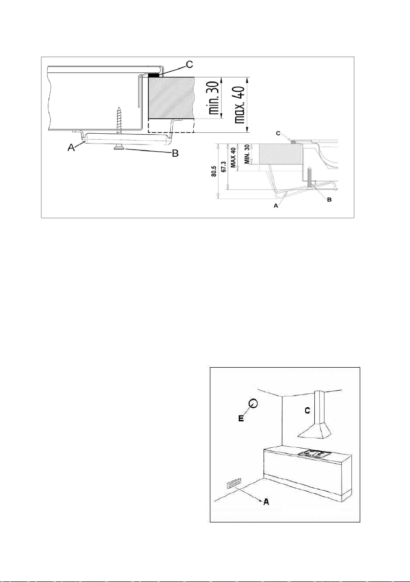
Ɋɚɡɦɟɪɵ ɜɵɪɟɡɚ, ɤɨɬɨɪɵɣ ɧɟɨɛɯɨɞɢɦɨ ɜɵɩɨɥɧɢɬɶ ɜ
ɫɬɨɥɟɲ
ɧɢɰɟ, ɚ ɬɚɤɠɟ ɦɢɧɢɦɚɥɶɧɵɟ ɪɚɫɫɬɨɹɧɢɹ ɦɟɠɞɭ
ɛɨɤɨɜɨɣ ɢ ɡɚɞɧɟɣ ɫɬɟɧɨɣ, ɢ ɪɚɡɦɟɪɵ ɩɪɢɛɨɪɚ,
ɩɨɤɚɡɚɧɵ ɧɚ ɪɢɫ. 1 ɧɢɠɟ.
Ɋɢɫ. 1.
4
Page 7

ȼɧɢɦɚɧɢɟ:
ȼ ɫɥɭɱɚɟ, ɟɫɥɢ ɩɨɜɟɪɯɧɨɫɬɶ ɭɫɬɚɧɚɜɥɢɜɚɟɬɫɹ ɧɚɞ ɤɭɯɨɧɧɨɣ ɬɭɦɛɨɣ, ɜ ɤɨɬɨɪɨɣ ɧɟɬ ɞɭɯɨɜɤɢ, ɦɟɠɞɭ
ɩɨɜɟɪɯɧɨɫɬɶɸ ɢ ɧɚɯɨɞɹɳɟɣɫɹ ɩɨɞ ɧɟɣ ɬɭɦɛɨɣ ɧɟɨɛɯɨɞɢɦɨ ɭɫɬɚɧɨɜɢɬɶ ɪɚɡɞɟɥɢɬɟɥɶɧɭɸ ɩɥɚɧɤɭ, ɧɚ
ɦɢɧɢɦɚɥɶɧɨɦ
ȼ ɫɥɭɱɚɟ, ɟɫɥɢ ɩɨɜɟɪɯɧɨɫɬɶ ɭɫɬɚɧɚɜɥɢɜɚɟɬɫɹ ɧɚɞ ɞɭɯɨɜɤɨɣ, ɪɚɡɦɟɫɬɢɬɟ ɪɚɡɞɟɥɢɬɟɥɶɧɭɸ ɩɥɚɧɤɭ ɩɨɞ
ɩɨɜɟɪɯɧɨɫɬɶɸ, ɧɚ ɦɢɧɢɦɚɥɶɧɨɦ ɪɚɫɫɬɨɹɧɢɢ ɜ 15 ɦɦ, ɚ ɬɚɤɠɟ ɫɥɟɞɭɣɬɟ ɭɤɚɡɚɧɢɹɦ ɩɪɨɢɡɜɨɞɢɬɟɥɹ ɩɨ
ɭɫɬɚɧɨɜɤɟ ɞɭɯɨɜɤɢ
Ⱦɥɹ ɨɛɨɢɯ ɜɵɲɟɭɤɚɡɚɧɧɵɯ ɫɥɭɱɚɟɜ, ɩɨɞɤɥɸɱɟɧɢɟ ɤ ɷɥɟɤɬɪɨɫɟɬɢ ɞɨɥɠɧɨ ɛɵɬɶ ɩɪɨɢɡɜɟɞɟɧɨ ɨɬɞɟɥɶɧɨ
ɞɥɹ ɤɚɠɞɨɝɨ ɩɪɢɛɨɪɚ, ɤɚɤ ɜ
Ɋɟɤɨɦɟɧɞɭɟɬɫɹ ɭɫɬɚɧɚɜɥɢɜɚɬɶ ɞɭɯɨɜɤɭ ɫ ɫɢɫɬɟɦɨɣ ɩɪɢɧɭɞɢɬɟɥɶɧɨɣ ɜɟɧɬɢɥɹɰɢɢ.
ɍɋɌȺɇɈȼɄȺ ȻȿɁ ȾɍɏɈȼɄɂ ɍɋɌȺɇɈȼɄȺ ɇȺȾ ȾɍɏɈȼɄɈɃ
ɪɚɫɫɬɨɹɧɢɢ ɜ 10 ɦɦ ɨɬ ɩɨɜɟɪɯɧɨɫɬɢ.
, ɨɛɟɫɩɟɱɢɜ ɩɪɢ ɷɬɨɦ ɞɨɫɬɚɬɨɱɧɭɸ ɜɟɧɬɢɥɹɰɭɸ ɜɨɡɞɭɯɚ, ɤɚɤ ɩɨɤɚɡɚɧɨ ɧɚ ɪɢɫ. 2.
ɰɟɥɹɯ ɛɟɡɨɩɚɫɧɨɫɬɢ, ɬɚɤ ɢ ɞɥɹ ɭɞɨɛɫɬɜɚ ɨɬɤɥɸɱɟɧɢɹ ɨɞɧɨɝɨ ɢɡ ɩɪɢɛɨɪɨɜ.
F = 10mm
H = 50mm
Ʉɪɟɩɥɟɧɢɟ ɩɨɜɟɪɯɧɨɫɬɢ ɤ ɫɬɨɥɟɲɧɢɰɟ.
Ⱦɥɹ ɤɪɟɩɥɟɧɢɹ ɩɨɜɟɪɯɧɨɫɬɢ ɤ ɫɬɨɥɟɲɧɢɰɟ, ɫɥɟɞɭɣɬɟ ɧɢɠɟɩɪɢɜɟɞɟɧɧɵɦ ɭɤɚɡɚɧɢɹɦ, ɫɦ. ɪɢɫ. 3 ɧɢɠɟ:
- Ɋɚɫɩɨɥɨɠɢɬɟ ɫɩɟɰɢɚɥɶɧɵɣ ɭɩɥɨɬɧɢɬɟɥɶ (C), ɢɦɟɸɳɢɣɫɹ ɜ ɤɨɦɩɥɟɤɬɚɰɢɢ, ɜɞɨ
ɫɬɨɥɟɲɧɢɰɵ, ɫɦ. ɫɯɟɦɭ ɧɚ ɪɢɫ. 1 ɜɵɲɟ. Ʉɪɚɹ ɭɩɥɨɬɧɢɬɥɹ ɧɟ ɞɨɥɠɧɵ ɧɚɥɟɝɚɬɶ ɞɪɭɝ ɧɚ ɞɪɭɝɚ, ɢ ɞɨɥɠɧɵ
ɫɨɣɬɢɫɶ ɛɟɡ ɪɚɡɪɵɜɨɜ.
- Ɋɚɫɩɨɥɨɠɢɬɟ ɩɨɜɟɪɯɧɨɫɬɶ ɜ ɩɪɨɟɦ, ɬɚɤɢɦ ɨɛɪɚɡɨɦ, ɱɬɨɛɵ ɨɧɚ
- Ɂɚɤɪɟɩɢɬɟ ɩɨɜɟɪɯɧɨɫɬɶ ɤ ɫɬɨɥɟɲɧɢɰɟ, ɩɪɢ ɩɨɦɨɳɢ ɫɩɟɰɢɚɥɶɧɵɯ ɤɪɟɩɟɠɧɵɯ ɫɤɨɛ (A) ɢ ɲɭɪɭɩɨɜ (B),
ɢɦɟɸɳɢɯɫɹ ɜ ɤɨɦɩɥɟɤɬɚɰɢɢ. ɋɦ. ɪɢɫ. 3 ɧɢɠɟ.
ȼɧɢɦɚɧɢɟ: ɜɟɪɧɚɹ ɭɫɬɚɧɨɜɤɚ ɭɩɥɨɬɧɢɬɟɥɹ ɝɚɪɚɧɬɢɪɭɟɬ ɡɚɳɢɬ
ɩɨɜɟɪɯɧɨɫɬɶ.
(ɦɢɧ.)
(ɦɢɧ.)
G = 15mm
D = 120cm²
(ɦɢɧ.)
Ɋɚɡɞɟɥɢɬɟɥɶɧɚɹ ɩɥɚɧɤɚ
Ɋɢɫ. 2.
E = 180cm²
C = 30mm
ɧɚɯɨɞɢɥɚɫɶ ɪɨɜɧɨ ɩɨ ɰɟɧɬɪɭ.
ɭ ɨɬ ɩɨɩɚɞɚɧɢɹ ɠɢɞɤɨɫɬɢ ɩɨɞ ɜɚɪɨɱɧɭɸ
(ɦɢɧ.)
ɥɶ ɜɧɟɲɧɟɝɨ ɩɟɪɢɦɟɬɪɚ
5
Page 8
Ɋɢɫ. 3.
ȼɵɛɨɪ ɩɨɦɟɳɟɧɢɹ ɞɥɹ ɭɫɬɚɧɨɜɤɢ ɢ ɜɵɜɨɞ ɩɪɨɞɭɤɬɨɜ ɝɨɪɟɧɢɹ.
ɉɪɢɛɨɪ ɞɨɥɠɟɧ ɛɵɬɶ ɭɫɬɚɧɨɜɥɟɧ ɜ ɩɨɦɟɳɟɧɢɢ, ɫɨɨɬɜɟɬɫɬɜɭɸɳɟɦ ɞɟɣɫɬɜɭɸɳɢɦ ɧɨɪɦɚɦ ɢ ɦɟɫɬɧɵɦ
ɡɚɤɨɧɚɦ.
Ɍɟɯɧ ɢɱɟɫɤɢɣ ɩɟɪɫɨɧɚɥ, ɩɪɨɢɡɜɨɞɹɳɢɣ ɭɫɬɚɧɨɜɤɭ ɞɚɧɧɨɝɨ ɩɪɢɛɨɪɚ, ɞɨɥɠ
ɡɚɤɨɧɵ ɩɨ ɜɟɧɬɢɥɹɰɢɢ ɢ ɜɵɜɨɞɭ ɩɪɨɞɭɤɬɨɜ ɝɨɪɟɧɢɹ.
Ʉɨɥɢɱɟɫɬɜɨ ɜɨɡɞɭɯɚ, ɧɟɨɛɯɨɞɢɦɨɝɨ ɞɥɹ ɝɨɪɟɧɢɹ, ɫɨɫɬɚɜɥɹɟɬ 2m
ɟɧ ɫɨɛɥɸɞɚɬɶ ɞɟɣɫɬɜɭɸɳɢɟ
3
/h ɧɚ 1 kW ɝɚɡɨɜɨɣ ɦɨɳɧɨɫɬɢ
ɭɫɬɚɧɚɜɥɢɜɚɟɦɨɝɨ ɩɪɢɛɨɪɚ.
ɏɚɪɚɤɬɟɪɢɫɬɢɤɢ ɩɨɦɟɳɟɧɢɹ
ȼ ɩɨɦɟɳɟɧɢɢ, ɜ ɤɨɬɨɪɨɦ ɛɭɞɟɬ ɭɫɬɚɧɜɥɢɜɚɬɶɫɹ ɝɚɡɨɜɵɣ ɩɪɢɛɨɪ, ɞɨɥɠɟɧ ɛɵɬɶ ɞɨɫɬɚɬɨɱɧɵɣ ɩɪɢɬɨɤ
ɫɜɟɠɟɝɨ ɜɨɡɞɭɯɚ, ɞɥɹ ɨɛɟɫɩɟɱɟɧɢɹ ɤɨɪɪɟɤɬɧɨɝɨ ɝɨɪɟɧɢɹ ɝɚɡɚ.
ȿɫɬɟɫɬɜɟɧɧɵɣ ɩɪɢɬɨɤ ɜɨɡɞɭɯɚ
ɜɧɟɲɧɟɣ ɫɬɟɧɟ ɩɨɦɟɳɟɧɢɹ, ɩɥɨɳɚɞɶ ɤɨɬɨɪɨɝɨ ɞɨɥɠɧɚ ɛɵɬɶ ɧɟ ɦɟɧɟɟ 100 ɫɦ
ȼ ɫɥɭɱɚɟ ɭɫɬɚɧɨɜɤɢ ɩɪɢɛɨɪɨɜ ɛɟɡ ɝɚɡ-ɤɨɧɬɪɨɥɹ, ɩɥɨɳɚɞɶ ɞɚɧɧɨɝɨ ɨɬɜɟɪɫɬɢ ɹ ɞɨɥɠɧɚ ɫɨɫɬɚɜɥɹɬɶ ɧɟ
ɦɟɧɟɟ 200 ɫɦ
2
(A).
ɞɨɥɠɟɧ ɨɫɭɳɟɫɬɜɥɹɬɶɫɹ ɩɨɫɪɟɞɫɬɜɨɦ ɨɬɜɟɪɫɬɢɹ, ɜɵɩɨɥɧɟɧɧɨɝɨ ɧɚ
2
(A).
ɋɦ. ɪɢɫ. 4 ɧɢɠɟ.
C = ȼɵɬɹɠɤɚ ɞɥɹ ɜɵɜɨɞɚ ɩɪɨɞɭɤɬɨɜ ɝɨɪɟɧɢɹ
E = ɗɥɟɤɬɪɢɱɟɫɤɢɣ ɜɟɧɬɢɥɹɬɨɪ ɞɥɹ ɜɵɜɨɞɚ
ɩɪɨɞɭɤɬɨɜ ɝɨɪɟɧɢɹ
A = Ɉɬɜɟɪɫɬɢɟ ɞɥɹ ɩɪɢɬɨɤɚ ɜɨɡɞɭɯɚ
Ɋɢɫ. 4.
6
Page 9
Ɉɬɜɟɪɫɬɢɟ A ɞɨɥɠɧɨ ɛɵɬɶ ɜɫɟɝɞɚ ɫɜɨɛɨɞɧɵɦ. ɍɛɟɞɢɬɟɫɶ ɜ ɬɨɦ, ɱɬɨɛɵ ɨɧɨ ɧɟ ɛɵɥɨ ɩɪɟɝɪɚɠɞɟɧɨ, ɤɚɤ
ɢɡɧɭɬɪɢ, ɬɚɤ ɢ ɫɧɚɪɭɠɢ. Ɋɟɤɨɦɟɧɞɭɟɬɫɹ ɜɵɩɨɥɧɢɬɶ ɞɚɧɧɨɟ ɨɬɜɟɪɫɬɢɟ ɛɥɢɡɤɨ ɤ ɭɪɨɜɧɸ ɩɨɥɚ, ɧɚ
ɩɪɨɬɢɜɨɩɨɥɨɠɧɨɣ
ȿɫɥɢ ɧɟɬ ɜɨɡɦɨɠɧɨɫɬɢ ɜɵɩɨɥɧɢɬɶ ɞɚɧɧɨɟ ɨɬɜɟɪɫɬɢɟ ɜ ɩɨɦɟɳɟɧɢɢ, ɬɨ ɩɪɢɬɨɤ ɜɨɡɞɭɯɚ ɞɨɥɠɟɧ
ɨɛɟɫɩɟɱɢɜɚɬɶɫɹ ɢɡ ɩɪɢɥɟɝɚɸɳɟɝɨ ɜɟɧɬɢɥɢɪɭɟɦɨɝɨ ɩɨɦɟɳɟɧɢɹ, ɡɚ ɢɫɤɥɸɱɟɧɢɟɦ ɫɩɚɥɶɧɨɣ ɤɨɦɧɚɬɵ,
ɥɢɛɨ ɩɨɦɟɳɟɧɢɹ ɫ
ȼɵɯɨɞ ɩɪɨɞɭɤɬɨɜ ɝɨɪɟɧɢɹ
ɉɪɨɞɭɤɬɵ ɝɨɪɟɧɢɹ, ɜɵɪɚɛɚɬɵɜɚɟɦɵɟ ɝɚɡɨɜɵɦɢ ɩɪɢɛɨɪɚɦɢ, ɞɨɥɠɧɵ ɜɵɜɨɞɢɬɶɫɹ ɧɚɪɭɠɭ ɩɨɫɪɟɞɫɬɜɨɦ
ɜɵɬɹɠɤɢ (C), ɩɨɤɥɸɱɟɧɧɨɣ ɤ ɜɵɜɨɞɧɨɦɭ ɤɚɧɚɥɭ, ɥɢɛɨ ɧɚɩɪɹɦɭɸ ɧɚɪɭɠɭ. ɋɦ. ɪɢɫ. 4
ȼ ɫɥɭɱɚɟ, ɟɫɥɢ ɧɟɜɨɡɦɨɠɧɨ ɭɫɬɚɧɨɜɢɬɶ ɜɵɬɹɠɤɭ, ɧɟɨɛɯɨɞɢɦɨ ɭɫɬɚɧɨɜɢɬɶ ɷɥɟɤɬɪɢɱɟɫɤɢɣ ɜɟɧɬɢɥɹɬɨɪ (E),
ɤɬɨɪɵɣ ɧɟɨɛɯɨɞɢɦɨ ɪɚɫɩɨɥɨɠɢɬɶ ɧɚ ɜɧɟɲɧɟɣ ɫɬɟɧɟ ɩɨɦɟɳɟɧɢɹ, ɥɢɛɨ ɧɚ ɨɤɧɟ. ɋɦ. ɪɢɫ. 4 ɜɵɲɟ.
Ⱦɚɧɧɵɣ ɷɥɟ
ɱɚɫɚ ɨɧ ɦɨɝ ɨɛɟɫɩɟɱɢɬɶ ɫɦɟɧɭ ɤɨɥɢɱɟɫɬɜɚ ɜɨɡɞɭɯɚ, ɩɪɟɜɵɲɚɸɳɟɝɨ ɜ 3-5 ɪɚɡ ɨɛɴɟɦ ɜɨɡɞɭɯɚ ɜ
ɩɨɦɟɳɟɧɢɢ.
ɫɬɨɪɨɧɟ ɩɪɢɛɨɪɚ ɩɨ ɜɵɜɨɞɭ ɩɪɨɞɭɤɬɨɜ ɝɨɪɟɧɢɹ.
ɧɢɡɤɢɦ ɞɚɜɥɟɧɢɟɦ, ɥɢɛɨ ɥɸɛɨɝɨ ɢɧɨɝɨ ɨɩɚɫɧɨɝɨ ɩɨɦɟɳɟɧɢɹ.
ɜɵɲɟ.
ɤɬɪɢɱɟɫɤɢɣ ɜɟɧɬɢɥɹɬɨɪ ɞɨɥɠɟɧ ɢɦɟɬɶ ɞɨɫɬɚɬɨɱɧɭɸ ɦɨɳɧɨɫɬɶ, ɱɬɨɛɵ ɜ ɬɟɱɟɧɢɟ ɤɚɠɞɨɝɨ
3. ɉɈȾɄɅɘɑȿɇɂȿ Ʉ ɋȿɌɂ ɗɅȿɄɌɊɈɉɂɌȺɇɂə
ɉɪɟɠɞɟ ɱɟɦ ɩɪɢɫɬɭɩɢɬɶ ɤ ɩɨɞɤɥɸɱɟɧɢɸ ɩɪɢɛɨɪɚ ɤ ɫɟɬɢ ɷɥɟɤɬɪɨɩɢɬɚɧɢɹ, ɩɪɨɜɟɪɶɬɟ, ɫɨɨɬɜɟɬɫɬɜɭɟɬ ɥɢ
ɧɚɩɪɹɠɟɧɢɟ ɢ ɱɚɫɬɨɤɚ ɬɨɤɚ ɭɤɚɡɚɧɧɵɦ ɜ ɞɚɧɧɨɣ ɡɚɜɨɞɫɤɨɣ ɬɚɛɥɢɱɤɟ, ɚ ɬɚɤɠɟ ɫɨɨɬɜɟɬɫɬɜɭɟɬ ɥɢ
ɷɥɟɤɬɪɨɩɪɨɜɨɞ ɦɨɳɧɨɫɬɢ ɩɪɢɛɨɪɚ
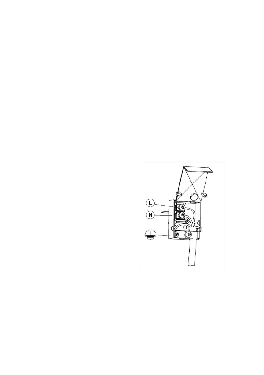
ɋɨɟɞɧɢɟɧɢɟ ɤɚɛɟɥɹ ɷɥɟɤɬɪɨɩɢɬɚɧɢɹ
ɄɈɊɂɑɇȿȼɕɃ - (L)
ɋɂɇɂɃ - (N)
ɀȿɅɌɈ-ɁȿɅȿɇɕɃ – ɁȺɁȿɆɅȿɇɂȿ ( Ũ )
, ɭɤɚɡɚɧɧɨɣ ɜ ɡɚɜɨɞɫɤɨɣ ɬɚɛɥɢɱɤɟ ɫ ɬɟɯɧɢɱɟɫɤɢɦɢ ɞɚɧɧɵɦɢ.
Ɋɢɫ. 5.
1. Ɉɬɤɪɨɣɬɟ ɤɥɟɦɦɧɭɸ ɤɨɪɨɛɤɭ ɩɪɢ ɩɨɦɨɳɢ ɨɬɜɟɪɬɤɢ, ɩɨɦɟɫɬɢɜ ɟɟ
ɩɨɬɹɧɢɬɟ ɢ ɨɬɤɪɨɣɬɟ ɤɪɵɲɤɭ.
2. ɍɫɬɚɧɨɜɢɬɟ ɤɚɛɟɥɶ, ɨɬɤɪɭɬɢɬɟ ɲɭɪɭɩ ɤɚɛɟɥɶɧɨɝɨ ɡɚɠɢɦɚ, ɢ ɬɪɢ ɲɭɪɭɩɚ ɤɨɧɬɚɤɬɨɜ L- N- Ũ , ɢ ɡɚɬɟɦ
ɡɚɮɢɤɫɢɪɭɣɬɟ ɩɪɨɜɨɞɚ ɩɨɞ ɲɥɹɩɤ
3. ɉɨɦɟɫɬɢɬɟ ɤɚɛɟɥɶ ɜ ɫɨɨɬɜɟɬɫɬɜɭɸɳɟɟ ɨɬɜɟɪɫɬɢɟ.
4. Ɂɚɤɪɨɣɬɟ ɤɪɵɲɤɭ ɤɥɟɦɦɧɨɣ ɤɨɪɨɛɤɢ.
ɋɦ. ɪɢɫ. 5 ɜɵɲɟ.
ȼɧɢɦɚɧɢɟ: ɧɚɥɢɱɢɟ ɡɚɡɟɦɥɟɧɢɹ ɨɛɹɡɚɬɟɥɶɧɨ ɩɨ ɡɚɤɨɧɭ.
ɉɨɞɤɥɸɱɟɧɢɟ ɷɥɟɤɬɪɨɩɪɨɜɨɞɚ ɤ ɫɟɬɢ
ɚɦɢ ɲɭɪɭɩɨɜ, ɜ ɫɨɨɬɜɟɬɫɬɜɢɢ ɫ ɰɜɟɬɚɦɢ.
ɩɨɞ ɛɨɤɨɜɵɦɢ ɲɩɨɧɤɚɦɢ ɧɚ ɤɪɵɲɤɟ,
ɷɥɟɤɬɪɨɩɢɬɚɧɢɹ
7
Page 10
Ⱦɥɹ ɩɪɹɦɨɝɨ ɩɨɞɤɥɸɱɟɧɢɹ ɤ ɫɟɬɢ ɷɥɟɤɬɪɨɩɢɬɚɧɢɹ, ɧɟɨɛɯɨɞɢɦɨ ɩɪɟɞɭɫɦɨɬɪɟɬɶ ɧɚɥɢɱɢɟ ɜɵɤɥɸɱɚɬɟɥɹ,
ɝɚɪɚɧɬɢɪɭɸɳɟɝɨ ɨɬɤɥɸɱɟɧɢɟ ɨɬ ɷɥɟɬɤɪɨɫɟɬɢ, ɫ ɪɚɫɫɬɨɹɧɢɟɦ ɦɟɠɞɭ ɤɨɧɬɚɤɬɚɦɢ, ɤɨɬɨɪɨɟ ɩɨɡɜɨɥɹɟɬ
ɩɨɥɧɨɟ ɨɬɤɥɸɱɟɧɢɟ ɜ ɭɫɥɨɜɢɹɯ ɧɚɩɪɹɠɟɧɢɹ ɤɚɬɟɝɨɪɢɢ III, ɜ ɫɨɨɬɜɟɬɫɬɜɢɢ ɫ
ɉɨɞɫɨɟɞɢɧɢɬɟ ɫɬɚɧɞɚɪɬɧɭɸ ɜɢɥɤɭ, ɫɨɨɬɜɟɬɫɬɜɭɸɳɭɸ ɯɚɪɚɤɬɟɪɢɫɬɢɤɚɦ, ɭɤɚɡɚɧɧɵɦ ɜ ɡɚɜɨɞɫɤɨɣ
ɬɚɛɥɢɱɤɟ ɫ ɬɟɯɧɢɱɟɫɤɢɦɢ ɞɚɧɧɵɦɢ.
ɇɟɨɛɯɨɞɢɦɨ ɪɚɫɩɨɥɨɠɢɬɶ ɷɥɟɤɬɪɨɩɪɨɜɨɞ ɬɚɤɢɦ ɨɛɪɚɡɨɦ, ɱɬɨɛɵ ɨɧ ɧɟ ɧɚɝɪɟɜɚɥɫɹ ɜɵ
ɨɞɧɨɣ ɬɨɱɤɟ.
ɍɫɬ ɚɧ ɨɜ ɳɢɤ ɧɟɫɟɬ ɨɬɜɟɬɫɬɜɟɧɧɨɫɬɶ ɡɚ ɤɨɪɪɟɤɬɧɨɟ ɩɨɞɤɥɸɱɟɧɢɟ ɤ ɷɥɟɤɬɪɨɫɟɬɢ, ɚ ɬɚɤɠɟ ɡɚ ɫɨɛɥɸɞɟɧɢɟ
ɩɪɚɜɢɥ ɩɨ ɬɟɯɧɢɤɟ ɛɟɡɨɩ ɚɫɧɨɫɬɢ.
ɉɟɪɟɞ ɩɨɞɤɥɸɱɟɧɢɟɦ ɤ ɷɥɟɬɤɪɨɫɟɬɢ, ɭɞɨɫɬɨɜɟɪɶɬɟɫɶ ɜ ɬɨɦ, ɱɬɨ:
- ɪɨɡɟɬɤɚ ɢɦɟɟɬ ɡɚɡɟɦɥɟɧɢɟ,
- ɪɨɡɟɬɤɚ ɜ ɫɨɫɬɨɹɧɢɢ ɜɵɞɟɪɠɚɬɶ ɦɚɤɫɢɦɚɥɶɧɭɸ ɩɨɬɪɟɛɥɹɟɦɭɸ ɦɨɳɧɨɫɬɶ ɩɨɜɟɪɯɧɨɫɬɢ, ɭɤɚɡɚɧɧɭɸ ɜ
ɡɚɜɨɞɫɤɨɣ ɬɚɛɥɢɱɤɟ ɫ ɬɟɯɧɢɱɟɫɤɢɦɢ ɞɚɧɧɵɦɢ.
- ɧɚɩɪɹɠɟɧɢɟ ɬɨɤɚ ɫɨɨɬɜɟɬɫɬɜɭɟɬ ɞɚɧɧɵɦ, ɭɤɚɡɚɧɧɵɦ ɜ ɡɚɜɨɞɫɤɨ
ɞɚɧɧɵɦɢ.
- ɪɨɡɟɬɤɚ ɫɨɜɦɟɫɬɢɦɚ ɫ ɜɢɥɤɨɣ ɩɪɢɛɨɪɚ. ȼ ɩɪɨɬɢɜɧɨɦ ɫɥɭɱɚɟ, ɡɚɦɟɧɢɬɟ ɪɨɡɟɬɤɭ, ɥɢɛɨ ɜɢɥɤɭ.
- ɧɟ ɢɫɩɨɥɶɡɭɣɬɟ ɬɪɨɣɧɢɤɢ ɥɢɛɨ ɭɞɥɢɧɢɬɟɥɢ.
- ɩɨɫɥɟ ɭɫɬɚɧɨɜɤɢ ɩɪɢɛɨɪɚ ɷɥɟɤɬɪɨɩɪɨɜɨɞ
- ɷɥɟɤɬɪɨɩɪɨɜɨɞ ɧɟ ɞɨɥɠɟɧ ɛɵɬɶ ɫɨɝɧɭɬ, ɥɢɛɨ ɫɞɚɜɥɟɧ.
- ɧɟɨɛɯɨɞɢɦɨ ɪɟɝɭɥɹɪɧɨ ɩɪɨɜɟɪɹɬɶ ɷɥɟɤɬɪɨɩɪɨɜɨɞ, ɢ ɜ ɫɥɭɱɚɟ ɧɟɨɛɯɨɞɢɦɨɫɬɢ, ɟɝɨ ɡɚɦɟɧɚ ɞɨɥɠɧɚ
ɩɪɨɢɡɜɨɞ
ɉɪɨɢɡɜɨɞɢɬɟɥɶ ɧɟ ɧɟɫɟɬ ɨɬɜɟɬɫɬɜɟɧɧɨɫɬɢ ɜ ɫɥɭɱɚɟ ɧɟɫɨɛɥɸɞɟɧɢɹ ɥɸɛɨɝɨ ɢɡ ɜɵɲɟɭɤɚɡɚɧɧɵɯ
ɩɭɧɤɬɨɜ.
Ɂɚɦɟɧɚ ɷɥɟɤɬɪɨɩɪɨɜɨɞɚ
ȼ ɫɥɭɱɚɟ ɧɟɨɛɯɨɞɢɦɨɫɬɢ ɡɚɦɟɧɵ ɷɥɟɤɬɪɨɩɪɨɜɨɞɚ, ɢɫɩɨɥɶɡɭɣɬɟ ɷɥɟɤɬɪɨɩɪɨɜɨɞ ɫ
ɯɚɪɚɤɬɢɪɢɫɬɢɤɚɦɢ, ɤɚɤ ɢ ɨɪɢɝɢɧɚɥɶɧɵɣ ɷɥɟɤɬɪɨɩɪɨɜɨɞ, ɢɦɟɸɳɢɣɫɹ ɜ ɧɚɥɢɱɢɟ. Ⱦɚɧɧɵɣ ɩɪɨɜɨɞ ɞɨɥɠɧɟ
ɫɨɨɬɜɟɬɫɬɜɨɜɚɬɶ ɦɨɳɧɨɫɬɢ ɩɪɢɛɨɪɚ ɢ ɬɟɦɩɟɪɚɬɭɪɟ ɟɝɨ ɪɚɛɨɬɵ (ɬɢɩ T90°C).
ɀɟɥɬɨ-ɡɟɥɟɧɵɣ ɩɪɨɜɨɞ ɡɚɡɟɦɥɟɧɢɹ ɞɨɥɠɟɧ ɛɵɬɶ ɩɪɢɛɥɢɡɢɬɟ
Ⱦɥɹ ɩɨɞɤɥɸɱɟɧɢɹ ɝɚɡɨɜɵɯ ɩɨɜɟɪɯɧɨɫɬɟɣ ɢɫɩɨɥɶɡɭɣɬɟ ɷɥɟɤɬɪɨɲɧɭɪ ɫ ɞɢɚɦɟɬɪɨɦ ɫɟɱɟɧɢɹ Ø 0,75ɦɦ².
ȼɨ ɢɡɛɟɠɚɧɢɟ ɜɨɡɧɢɤɧɨɜɟɧɢɹ ɨɩɚɫɧɵɯ ɫɢɬɭɚɰɢɣ, ɡɚɦɟɧɭ ɷɥɟɤɬɪɨɩɪɨɜɨɞɚ ɞɨɥɠɟɧ ɩɪɨɢɡɜɨɞɢɬɶ
ɬɟɯɧɢɱɟɫɤɢɣ ɩɟɪɫɨɧɚɥ ɫɟɪɜɢɫɧɨɝɨ ɰɟɧɬɪɚ.
ɢɬɶɫɹ ɬɨɥɶɤɨ ɤɜɚɥɢɮɢɰɢɪɨɜɚɧɧɵɦ ɩɟɪɫɨɧɚɥɨɦ.
ɢ ɫɨɨɬɜɟɬɫɬɜɭɟɬ ɞɟɣɫɬɜɭɸɳɢɦ ɧɨɪɦɚɦ.
ɢ ɪɨɡɟɬɤɚ ɞɨɥɠɧɵ ɛɵɬɶ ɥɟɝɤɨ ɞɨɫɬɭɩɧɵ.
ɥɶɧɨ ɧɚ 2 ɫɦ. ɞɥɢɧɟɟ ɞɪɭɝɢɯ ɩɪɨɜɨɞɨɜ.
ɧɨɪɦɚɦɢ ɩɨ ɭɫɬɚɧɨɜɤɟ.
ɲɟ 50°C ɧɢ ɜ
ɣ ɬɚɛɥɢɱɤɟ ɫ ɬɟɯɧɢɱɟɫɤɢɦɢ
ɬɟɦɢ ɠɟ
ɉɈȾɄɅɘɑȿɇɂȿ ȽȺɁȺ
Ƚɚɡɨɜɚɹ ɫɢɫɬɟɦɚ ɞɨɥɠɧɚ ɫɨɨɬ ɜɟɬɫɬɜɨɜɚɬɶ ɞɟɣɫɬɭɸɳɢɦ ɧɨɪɦɚɦ ɜ ɫɬɪɚɧɟ ɭɫɬɚɧɨɜɤɢ ɩɪɢɛɨɪɚ.
Ɍɢɩ ɝɚɡɚ, ɧɚ ɤɨɬɨɪɵɣ ɧɚɫɬɪɨɟɧɚ ɩɨɜɟɪɯɧɨɫɬɶ, ɭɤɚɡɚɧ ɜ ɡɚɜɨɞɫɤɨɣ ɬɚɛɥɢɱɤɟ ɫ ɬɟɯɧɢɱɟɫɤɢɦɢ
ɞɚɧɧɵɦɢ, ɤɨɬɨɪɚɹ ɧɚɯɨɞɢɬɫɹ ɧɚ ɞɧɟ ɩɨɜɟɪɯɧɨɫɬɢ, ɚ ɬɚɤɠɟ ɧɚ ɭɩɚɤɨɜɤ
ɩɨɫɥɟɞɧɟɣ ɫɬɪɚɧɢɰɚ ɞɚɧɧɨɝɨ ɪɭɤɨɜɨɞɫɬɜɚ ɩɨ ɷɤɫɩɥɭɚɬɚɰɢɢ.
ɉɟɪɟɞ ɩɨɞɤɥɸɱɟɧɢɟɦ, ɩɨɜɟɪɯɧɨɫɬɶ ɧɟɨɛɯɨɞɢɦɨ ɧɚɫɬɪɨɢɬɶ ɧɚ ɬɢɩ ɝɚɡɚ, ɧɚ ɤɨɬɨɪɨɦ ɨɧɚ ɛɭɞɟɬ ɪɚɛɨɬɚɬɶ.
ɋɥɟɞɢɬɟ ɡɚ ɬɟɦ, ɱɬɨɛɵ ɬɪɭɛɚ ɧɟ ɤɚɫɚɥɚɫɶ ɞ
ɩɨɜɪɟɠɞɟɧɢɸ.
ɉɨɞɤɥɸɱɟɧɢɟ ɤ ɝɚɡɨɜɨɣ ɫɢɫɬɟɦɟ ɞɨɥɠɧɨ
ɨɫɭɳɟɫɬɜɟɥɹɬɶɫɹ ɬɨɥɶɤɨ ɄȼȺɅɂɎɂɐɂPɈȼȺɇɇɕɆ
ɉȿɊɋɈɇȺɅɈɆ, ɜ ɫɨɨɬɜɟɬɫɬɜɢɢ ɫ ɦɟɫɬɧɵɦɢ ɡɚɤɨɧɚɦɢ.
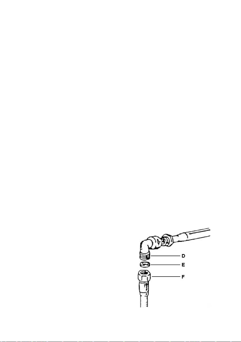
Ⱦɥɹ ɩɨɞɤɥɸɱɟɧɢɹ ɤ ɝɚɡɨɜɨɣ ɬɪɭɛɟ ɢɫɩɨɥɶɡɭɟɬɫɹ
ɫɟɨɞɢɧɢɬɟɥɶ
ɋɦ. ɪɢɫ. 6 ɧɢɠɟ.
D – ɫɨɟɞɢɧɢɬɟɥɶ
E – ɭɩɥɨɬɧɢɬɟɥɶ
F – ɝɚɡɨɜɚɹ ɬɪɭɛɚ
ɫ ɧɚɪɭɠɧɨɣ ɪɟɡɶɛɨɣ ½ ɞɸɣɦɚ.
ɜɢɠɭɳɢɯɫɹ ɩɪɟɞɦɟɬɨɜ, ɱɬɨ ɦɨɠɟɬ ɩɪɢɜɟɫɬɢ ɤ ɟɟ
ɟ, ɢ ɧɚ ɨɛɨɪɨɬɧɨɣ ɫɬɨɪɨɧɟ
Ɋɢɫ. 6.
8
Page 11

ȼɚɠɧɨ: ɞɥɹ ɬɨɝɨ, ɱɬɨɛɵ ɩɨɞɫɨɟɞɢɧɢɬɶ ɩɪɢɛɨɪ ɤ ɛɚɥɨɧɧɨɦɭ ɝɚɡɭ, ɦɟɠɞɭ ɬɪɭɛɨɣ ɢ ɝɚɡɨɜɵɦ ɛɚɥɨɧɨɦ
ɧɟɨɛɯɨɞɢɦɨ ɭɫɬɚɧɨɜɢɬɶ ɪɟɝɭɥɹɬɨɪ ɞɚɜɥɟɧɢɹ, ɫɨɨɬɜɟɬɫɬɜɭɸɳɢɣ ɞɟɣɫɬɜɭɸɳɢɦ ɧɨɪɦɚɦ.
ȼɧɢɦɚɧɢɟ: ɩɨɫɥɟ ɩɨɞɤɥɸɱɟɧɢɹ, ɩɪɨɜɟɪɶɬɟ, ɱɬɨɛɵ ɧɟ ɛ
ɦɵɥɶɧɭɸ ɜɨɞɭ, ɥɢɛɨ ɫɩɟɰɢɚɥɶɧɭɸ ɠɢɞɤɨɫɬɶ.
ɵɥɨ ɭɬɟɱɤɢ ɝɚɡɚ. ɂɫɩɨɥɶɡɭɣɬɟ ɞɥɹ ɷɬɨɝɨ
ɇȿ ɉɊɈȼȿɊəɃɌȿ ɍɌȿɑɄɍ ȽȺɁȺ ɉɊɂ ɉɈɆɈɓɂ ɈɌɄɊɕɌɈȽɈ ɉɅȺɆȿɇɂ
ȼɧɢɦɚɧɢɟ: ɡɚɩɪɟɳɚɟɬɫɹ ɢɫɩɨɥɶɡɨɜɚɬɶ ɝɢɛɤɢɟ ɪɟɡɢɧɨɜɵɟ ɲɥɚɧɝɢ ɢ ɫɨɟɞɢɧɢɬɟɥɢ, ɬɚɤ ɤɚɤ ɩɪɨɜɟɞɟɧɢɟ ɢɯ
ɤɨɧɬɪɨɥɹ ɧɟɜɨɡɦɨɠɧɨ.
ɇɚɫɬɪɨɣɤɚ ɬɢɩɚ ɝɚɡɚ.
Ⱦɚɧɧɭɸ ɩɨɜɟɪɯɧɨɫɬɶ ɦɨɠɧɨ ɢɫɩɨɥɶɡɨɜɚɬɶ ɫ ɪɚɡɥɢɱɧɵɦɢ ɬɢɩɚɦɢ ɝɚɡɚ. Ⱦɥɹ ɷɬɨɝɨ ɧɟɨɛɯɨɞɢɦɨ
ɩɪɨɢɡɜɟɫɬɢ ɡɚɦɟɧɭ ɠɢɤɥɟɪɨɜ
ȼ ɫɥɭɱɚɟ, ɟɫɥɢ ɡɚɩɚɫɧɵɟ ɠɢɤɥɟɪɵ ɧɟ ɩɨɫɬɚɜɥɹɸɬɫɹ ɜ ɤɨɦɩɥɟɤɬɚɰɢɢ ɩɨɜɟɪɯɧɨɫɬɢ, ɢɯ ɦɨɠɧɨ ɩɪɢɨɛɪɟɫɬɢ
ɜ ɚɜɬɨɪɢɡɢɪɨɜɚɧɧɵɯ ɋɟɪɜɢɫɧɵɯ ɰɟɧɬɪɚɯ.
Ⱦɥɹ ɜɵɛɨɪɚ ɜɟɪɧɨɝɨ ɬɢɩɚ ɠɢɤɥɟɪɚ ɞɥɹ ɡɚɦɟɧɵ, ɫɦ. ɬɚɛɥɢɰɭ ɧɢɠɟ.
ɀɢɤɥɟɪɵ ɨɩɪɟɞɟɥ
Ɂɚɦɟɧɚ ɠɢɤɥɟɪɨɜ.
:
ɋɧɢɦɢɬɟ ɪɟɲɟɬɤɢ ɢ ɤɪɵɲɤɢ ɝɨɪɟɥɨɤ ɫ ɩɨɜɟɪɯɧɨɫɬɢ; ɋɦ. ɪɢɫ. 7 ɧɢɠɟ.
ɹɸɬɫɹ ɩɨ ɞɢɚɦɟɬɪɭ, ɭɤɚɡɚɧɧɨɦɭ ɧɚ ɢɯ ɤɨɪɩɭɫɟ.
:
:
ɉɪɢ ɩɨɦɨɳɢ ɬɨɪɰɟɜɨɝɨ ɤɥɸɱɚ, ɫɧɢɦɢɬɟ ɫɬɚɪɵɣ
ɠɢɤɥɟɪ (J), ɢ ɡɚɦɟɧɢɬɟ ɟɝɨ ɧɚ ɧɨɜɵɣ ɠɢɤɥɟɪ,
ɫɨɨɬɜɟɬɫɬɜɭɸɳɟɝɨ ɪɚɡɦɟɪɚ.
:
ɉɨɫɬɚɜɶɬɟ ɝɨɪɟɥɤɢ ɢ ɪɟɲɟɬɤɢ ɧɚ ɩɪɟɠɧɢɟ ɦɟɫɬɚ.
ɝɚɡɨɜɵ ɯ ɝɨɪɟɥɨɤ.
Ɋɢɫ. 7.
ɌȺȻɅɂɐȺ ɀɂɄɅȿɊɈȼ
Ɍɢɩ ɝɚɡɚ G20 G30/G31
Ⱦɚɜɥɟɧɢɟ ɝɚɡɚ 20 mbar 28-30/37 mbar
ȽɨɪɟɥɤɚɆɚɤɫ. ɦɨɳɧɨɫɬɶ, kW Ɇɢɧ. ɦɨɳɧɨɫɬɶ, kW Ø ɠɢɤɥɟɪɚ
Ɇɚɥɟɧɶɤɚɹ 1.00 0.30 0.72 0.50
ɋɪɟɞɧɹɹ 1.75 0.44 0.97 0.65
Ȼɨɥɶɲɚɹ 3.00 0.75 1.15 0.85
Ɍɪɨɣɧɚɹ 3.30 1.50 1.24 0.91
9
Page 12

ɊȿȽɍɅɂɊɈȼɄȺ ɍɊɈȼɇə ɆɂɇɂɆȺɅɖɇɈȽɈ ɉɅȺɆȿɇɂ
ɉɪɢ ɡɚɦɟɧɟ ɬɢɩɚ ɝɚɡɚ, ɩɪɨɢɡɜɟɞɢɬɟ ɪɟɝɭɥɢɪɨɜɤɭ ɦɢɧɢɦɚɥɶɧɨɝɨ ɩɥɚɦɟɧɢ ɫɥɟɞɭɸɳɢɦ ɨɛɪɚɡɨɦ:
- ɡɚɠɝɢɬɟ ɝɨɪɟɥɤɭ ɢ ɫɧɢɦɢɬɟ ɩɟɪɟɤɥɸɱɚɬɟɥɶ;
- ɩɨɜɟɪɧɢɬɟ ɤɪɚɧ ɧɚ ɦɢɧɢɦɚɥɶɧɭɸ ɦɨɳɧɨɫɬɶ, ɡɚɬɟɦ ɩɨɫɬɚɜɶɬɟ ɧɚɫɚɞɤɭ ɨɬɜɟɪɬɤɢ ɜ ɪɟɝɭɥɢɪɨɜɨɱɧɵɣ
ɜɢɧɬ;
- ɡɚɬɹɧɢɬɟ ɪɟɝɭɥɢɪɨɜɨɱɧɵɣ ɜɢɧɬ ɞɥɹ
ɩɥɚɦɟɧɢ.
ɋɦ. ɪɢɫ. 7 ɜɵɲɟ.
ɉɪɢɦɟɱɚɧɢɟ: ɞɥɹ ɬɢɩɨɜ ɝɚɡɚ G30/G31 ɧɟɨɛɯɨɞɢɦɨ ɩɨɥɧɨɫɬɶɸ ɡɚɬɹɧɭɬɶ ɪɟɝɭɥɢɪɨɜɨɱɧɵɣ ɜɢɧɬ.
Ɂɚɬɟɦ ɩɪɨɜɟɪɶɬɟ ɧɚɫɬɪɨɣɤɭ ɫɥɟɞɭɸɳɢɦ ɨɛɪɚɡɨɦ:
- ɛɵɫɬɪɨ ɩɨɜɟɪɧɢɬɟ ɩɟɪɟɤɥɸ
ɩɨɝɚɫɥɨ ɥɢ ɩɥɚɦɹ.
- ɭ ɝɨɪɟɥɨɤ ɫ ɝɚɡ-ɤɨɧɬɪɨɥɟɦ ɩɥɚɦɹ ɞɨɥɠɧɨ ɫɥɟɝɤɚ ɤɚɫɚɬɶɫɹ ɬɟɪɦɨɩɚɪɵ
- ɟɫɥɢ ɜ ɬɟɱɟɧɢɟ ɧɟɫɤɨɥɶɤɢɯ ɦɢɧɭɬ ɩɥɚɦɹ
ɫɥɭɱɚɟ, ɩɨɜɬɨɪɢɬɟ ɜɵɲɟɭɤɚɡɚɧɧɵɟ ɞɟɣɫɬɜɢɹ, ɭɜɟɥɢɱɢɜ ɩɪɢ ɷɬɨɦ ɧɚɫɬɪɨɣɤɭ.
ɉɨɫɥɟ ɩɪɨɜɟɞɟɧɢɹ ɧɚɫɬɪɨɣɤɢ, ɩɥɚɦɹ ɞɨɥɠɧɨ ɛɵɬɶ ɦɚɥɟɧɶɤɢɦ, ɧɨ ɩɪɢ ɷɬɨɦ ɨɞɧɨɪɨɞɧɵɦ ɢ ɫɬɚɛɢɥɶɧɵɦ
ɩɨ ɜɫɟɣ ɨɤɪɭɠɧɨɫɬɢ ɝɨɪɟɥɤɢ.
ɭɦɟɧɶɲɟɧɢɹ ɩɥɚɦɟɧɢ, ɥɢɛɨ ɨɬɤɪɭɬɢɬɟ ɟɝɨ ɞɥɹ ɭɜɟɥɢɱɟɧɢɹ
ɱɚɬɟɥɶ ɫ ɦɚɤɫɢɦɚɥɶɧɨɣ ɧɚ ɦɢɧɢɦɚɥɶɧɭɸ ɦɨɳɧɨɫɬɶ, ɢ ɩɪɨɜɟɪɶɬɟ, ɧɟ
ɧɟ ɭɝɚɫɧɟɬ, ɪɟɝɭɥɢɪɨɜɤɚ ɩɪɨɢɡɜɟɞɟɧɚ ɤɨɪɪɟɤɬɧɨ. ȼ ɩɪɨɬɢɜɧɨɦ
ɗɄɋɉɅɍȺɌȺɐɂə ȽȺɁɈȼɈɃ ȼȺɊɈɑɇɈɃ ɉɈȼȿɊɏɇɈɋɌɂ
Ɉɩɢɫɚɧɢɟ ɪɚɡɥɢɱɧɵɯ ɬɢɩɨɜ ɩɨɜɟɪɯɧɨɫɬɟɣ
1.
2.
3.
4.
5.
6.
Ɋɢɫ. 8.1 Ɋɢɫ. 8.2
ɉɚɧɟɥɶ ɭɩɪɚɜɥɟɧɢɹ.
ɗɦɚɥɢɪɨɜɚɧɧɵɟ ɪɟɲɟɬɤɢ (ɥɟɜɚɹ ɢ ɩɪɚɜɚɹ).
ɑɭɝɭɧɧɵɟ ɪɟɲɟɬɤɢ (ɥɟɜɚɹ ɢ ɩɪɚɜɚɹ).
ɋɪɟɞɧɹɹ ɝɨɪɟɥɤɚ.
Ȼɨɥɶɲɚɹ ɝɨɪɟɥɤɚ.
Ɇɚɥɟɧɶɤɚɹ ɝɨɪɟɥɤɚ.
10
Page 13

ɍɉɊȺȼɅȿɇɂȿ ȽȺɁɈȼɈɃ ȼȺɊɈɑɇɈɃ ɉɈȼȿɊɏɇɈɋɌɖɘ
ɉɨɞɚɱɚ ɝɚɡɚ ɜ ɝɨɪɟɥɤɭ ɩɪɨɢɡɜɨɞɢɬɫɹ ɩɨɫɪɟɞɫɬɜɨɦ ɝɚɡɨɜɵɯ ɤɪɚɧɨɜ, ɪɟɝɭɥɢɪɭɟɦɵɯ ɩɟɪɟɤɥɸɱɚɬɟɥɹɦɢ, ɤɚɤ
ɩɨɤɚɡɚɧɨ ɧɚ ɪɢɫ. 9 ɧɢɠɟ.
ɋɨɨɬɜɟɬɫɬɜɭɸɳɢɟ ɫɢɦɜɨɥɵ ɧɚ ɪɚɡɥɢɱɧɵɯ ɦɨɞɟɥɹɯ ɦɨɝɭɬ ɛɵɬɶ ɧɚɧɟɫɟɧɵ ɤɚɤ ɧɚ
ɧɚ ɩɚɧɟɥɢ ɭɩɚɪɜɥɟɧɢɹ.
ɉɨɫɪɟɞɫɬɜɨɦ ɩɟɪɟɞɜɢɠɟɧɢɹ ɢɧɞɢɤɚɬɨɪɚ ɜ ɫɨɨɬɜɟɬɫɬɜɭɸɳɟɟ ɩɨɥɨɠɟɧɢɟ ɤɚɠɞɨɝɨ ɡɢ ɫɢɦɜɨɥɨɜ,
ɜɨɡɦɨɠɧɨ ɩɪɨɢɡɜɟɫɬɢ ɫɥɟɞɭɸɳɢɟ ɞɟɣɫɬɜɢɹ:
Ɣ
Ʉɪɚɧ ɡɚɤɪɵɬ (ɝɚɡ ɧɟ ɩɨɫɬɭɩɚɟɬ).
ɗɥɟɤɬɪɨɩɨɞɠɢɝ + ɦɚɤɫ. ɦɨɳɧɨɫɬɶ (ɦɚɤɫ. ɩɨɞɚɱɚ ɝɚɡɚ).
ɩɟɪɟɤɥɸɱɚɬɟɥɟ, ɬɚɤ ɢ
Ɇɢɧɢɦɚɥɶɧɚɹ ɦɨɳɧɨɫɬɶ (ɦɢɧ. ɩɨɞɚɱɚ ɝɚɡɚ ).
Ɋɢɫ. 9.
ɉɨɞɠɢɝ ɝɨɪɟɥɤɢ ɢ ɝɚɡ-ɤɨɧɬɪɨɥɶ
Ƚɚɡɨɜɵɟ ɩɨɜɟɪɯɧɨɫɬɢ ɨɫɧɚɳɟɧɵ ɷɥɟɤɬɪɢɱɟɫɤɢɦ ɩɨɞɠɢɝɨɦ, ɢɦɟɸɳɢɦɫɹ ɩɨɞ ɤɚɠɞɵɦ ɩɟɪɟɤɥɸɱɚɬɟɥɟɦ.
Ⱦɥɹ ɬɨɝɨ, ɱɬɨɛɵ ɩɨɠɞɟɱɶ ɝɨɪɟɥɤɭ, ɧɚɞɚɜɢɬɟ ɢ ɭɞɟɪɠɢɜɚ
ɦɚɫɤɢɦɚɥɶɧɨɣ ɦɨɳɧɨɫɬɢ, ɞɨ ɬɟɯ ɩɨɪ ɩɨɤɚ ɧɟ ɩɨɹɜɢɬɫɹ ɩɥɚɦɹ. Ɂɚɬɟɦ, ɩɨɜɟɪɧɢɬɟ ɩɟɪɟɤɥɸɱɚɬɟɥɶ ɢ
ɭɫɬɚɧɨɜɢɬɟ ɟɝɨ ɧɚ ɧɟɨɛɯɨɞɢɦɨɣ ɦɨɳɧɨɫɬɢ ɩɥɚɦɟɧɢ.
ɗɥɟɤɬɪɨɩɨɞɠɢɝ ɧɟɥɶɡɹ ɭɞɟɪɠɢɜɚɬɶ
ɜɤɥɸɱɢɬɫɹ, ɩɨɞɨɠɞɢɬɟ 1 ɦɢɧɭɬɭ, ɢ ɫɧɨɜɚ ɩɨɩɪɨɛɭɣɬɟ ɜɤɥɸɱɢɬɶ ɷɥɟɤɬɪɨɩɨɞɠɢɝ.
ɉɪɢɦɟɱɚɧɢɟ: ɟɫɥɢ ɝɚɡɨɫɧɚɛɠɟɧɢɟ ɜ ȼɚɲɟɦ ɪɚɣɨɧɟ ɧɟ ɩɨɡɜɨɥɹɟɬ ɥɟɝɤɨɝɨ ɡɚɠ
ɜɵɲɟɭɤɚɡɚɧɧɵɟ ɞɟɣɫɬɜɢɹ, ɭɛɟɞɢɜɲɢɫɶ, ɱɬɨ ɧɚ ɩɨɜɟɪɯɧɨɫɬɢ ɧɟɬ ɩɨɫɭɞɵ, ɢ ɩɨɜɟɪɧɢɬɟ ɩɟɪɟɤɥɸɱɚɬɟɥɶ ɧɚ
ɦɚɤɫɢɦɚɥɶɧɭɸ ɦɨɳɧɨɫɬɶ.
ȼɚɠɧɨ: Ⱦɚɧɧɵɟ ɝɚɡɨɜɵɟ ɩɨɜɟɪɯɧɨɫɬɢ ɢɦɟɸɬ ɫɢɫɬɟɦɭ ɝɚɡ-ɤɨɧɬɪɨɥɹ, ɤɨɬɨɪɚɹ ɩɟɪɟɤɪɵɜɚɟɬ ɩɨɞɚɱɭ ɝɚɡɚ
ɜ ɫɥɭɱɚɟ
, ɟɫɥɢ ɩɥɚɦɹ ɩɨɝɚɫɥɨ ɩɨ ɤɚɤɨɣ-ɥɢɛɨ ɩɪɢɱɢɧɟ. ɉɪɢ ɡɚɠɢɝɚɧɢɢ ɝɨɪɟɥɤɢ ɭɞɟɪɠɢɜɚɣɬɟ
ɩɟɪɟɤɥɸɱɚɬɟɥɶ ɜ ɬɟɱɟɧɢɟ 4-5 ɫɟɤɭɧɞ ɞɥɹ ɬɨɝɨ, ɱɬɨɛɵ ɧɚɝɪɟɥɚɫɶ ɬɟɪɦɨɩɚɪɚ ɝɚɡ-ɤɨɧɬɪɨɥɹ, ɜ ɩɪɨɬɢɜɧɨɦ
ɫɥɭɱɚɟ ɩɨɞɚɱɚ ɝɚɡɚ ɨɫɬɚɧɨɜɢɬɫɹ.
ɛɨɥɟɟ ɱɟɦ ɧɚ 15 ɫɟɤɭɧɞ. ȿɫɥɢ ɜ ɬɟɱɟɧɢɟ 15 ɫɟɤɭɧɞ ɝɨɪɟɥɤɚ ɧɟ
ɣɬɟ ɩɟɪɟɤɥɸɱɚɬɟɥɶ, ɩɨɜɟɪɧɭɜ ɟɝɨ ɜ ɩɨɥɨɠɟɧɢɟ
ɢɝɚɧɢɹ ɝɨɪɟɥɤɢ, ɩɨɜɬɨɪɢɬɟ
ȼɇɂɆȺɇɂȿ
ɉɟɪɟɤɥɸɱɚɬɟɥɶ ɞɨɥɠɟɧ ɜɫɟɝɞɚ ɧɚɯɨɞɢɬɶɫɹ ɜ ɩɨɥɨɠɟɧɢɢ ɦɟɠɞɭ ɦɚɤɫɢɦɚɥɶɧɨɣ ɢ ɦɢɧɢɦɚɥɶɧɨɣ
ɦɨɳɧɨɫɬɶɸ. ɇɟ ɪɚɫɩɨɥɚɝɚɣɬɟ ɩɟɪɟɤɥɸɱɚɬɟɥɶ ɦɟɠɞɭ ɦɚɤɫɢɦɚɥɶɧɨɣ ɦɨɳɧɨɫɬɶɸ ɢ ɩɨɥɨɠɟɧɢɟɦ ȼɵɤɥ.
ȿɫɥɢ ɝɨɪɟɥɤɚ ɡɚɠɢɝɚɟɬɫɹ
ɩɨɜɟɪɯɧɨɫɬɶ ɢ ɫɜɹɠɢɬɟɫɶ ɫ ɋɟɪɜɢɫɧɵɦ ɰɟɧɬɪɨɦ.
ȼɵɛɨɪ ɝɨɪɟɥɤɢ
ɋɢɦɜɨɥɵ, ɢɦɟɸɳɢɟɫɹ ɧɚ ɩɚɧɟɥɢ ɭɩɪɚɜɥɟɧɢɹ, ɪɹɞɨɦ ɫ ɩɟɪɟɤɥɸɱɚɬɟɥɹɦɢ, (ɫɦ. ɪɢɫ. 9 ɜɵɲɟ) ɭɤɚɡɵɜɚ
ɤɚɤɨɣ ɝɨɪɟɥɤɟ ɫɨɨɬɜɟɬɫɬɜɭɟɬ ɤɚɠɞɵɣ ɩɟɪɟɤɥɸɱɚɬɟɥɶ.
Ⱦɥɹ ɬɨɝɨ ɱɬɨɛɵ ɜɵɛɪɚɬɶ ɩɨɞɯɨɞɹɳɭɸ ɝɨɪɟɥɤɭ, ɧɟɨɛɯɨɞɢɦɨ ɭɱɢɬɵɜɚɬɶ ɞɢɚɦɟɬɪ ɩɨɫɭɞɵ, ɚ ɬɚɤɠɟ ɟɟ
ɨɛɴɟɦ. (ɫɦ. ɬɚɛɥɢɰɭ ɧɢɠɟ).
Ⱦɥɹ ɬɨɝɨ, ɱɬɨɛɵ
ɩɪɨɩɨɪɰɢɨɧɚɥɶɧɨ ɫɨɨɬɜɟɬɫɬɜɨɜɚɬɶ ɩɥɨɳɚɞɢ ɩɥɚɦɟɧɢ ɤɚɠɞɨɣ ɝɨɪɟɥɤɢ.
:
ɫ ɬɪɭɞɨɦ, ɥɢɛɨ ɟɫɥɢ ɩɥɚɦɹ ɜɵɫɨɤɨɟ ɢ ɧɟɫɬɚɛɢɥɶɧɨɟ, ɜɵɤɥɸɱɢɬɟ ɝɚɡɨɜɭɸ
ɨɛɟɫɩɟɱɢɬɶ ɯɨɪɨɲɢɟ ɪɟɡɭɥɶɬɚɬɵ ɜ ɩɪɢɝɨɬɨɜɥɟɧɢɢ ɛɥɸɞ, ɞɢɚɦɟɬɪ ɩɨɫɭɞɵ ɞɨɥɠɟɧ
11
ɸɬ,
Page 14

Ɍɚɛɥɢɰɚ ɞɢɚɦɟɬɪɚ ɩɨɫɭɞɵ
Ɍɢɩ ɝɨ ɪɟɥɤɢ
Ɇɚɥɟɧɶɤɚɹ
ɋɪɟɞɧɹɹ 160 200 160
Ȼɨɥɶɲɚɹ 200 240 160 200
Ɍɪɨɣɧɚɹ 240 260 200 220
ɂɋɉɈɅɖɁɈȼȺɇɂȿ ɊȿɒȿɌɈɄ
Ɋɟɲɟɬɤɢ ɩɪɟɞɧɚɡɧɚɱɟɧɵ ɞɥɹ ɛɨɥɟɟ ɛɟɡɨɩɚɫɧɨɝɨ ɢ ɩɪɨɫɬɨɝɨ ɢɫɩɨɥɶɡɨɜɚɧɢɹ ɜɚɪɨɱɧɨɣ ɩɨɜɟɪɯɧɨɫɬɢ.
ɉɪɟɠɞɟ ɱɟɦ ɢɫɩɨɥɶɡɨɜɚɬɶ ɩɨɜɟɪɯɧɨɫɬɶ, ɭɛɟɞɢɬɟɫɶ ɜ ɬɨɦ,
ɍɛɟɞɢɬɟɫɶ ɬɚɤɠɟ, ɱɬɨɛɵ ɪɟɡɢɧɨɜɵɟ ɨɩɨɪɵ ɩɨɞ ɪɟɲɟɬɤɚɦɢ ɛɵɥɢ ɪɚɫɩɨɥɨɠɟɧɵ ɤɨɪɪɟɤɬɧɨ.
Ⱥɞɚɩɬɟɪ ɞɥɹ ɦɚɥɟɧɶɤɨɣ ɩɨɫɭɞɵ (Ɋɢɫ. 10).
Ⱥɞɚɩɬɟɪ ɞɥɹ ɦɚɥɟɧɶɤɨɣ ɩɨɫɭɞɵ ɧɟɨɛɯɨ
ɦɚɥɟɧɶɤɨɝɨ ɞɢɚɦɟɬɪɚ. ɗɬɨ ɧɟɨɛɯɨɞɢɦɨ ɞɥɹ ɬɨɝɨ, ɱɬɨɛɵ ɩɪɟɞɨɬɜɪɚɬɢɬɶ ɩɚɞɟɧɢɟ ɦɚɥɟɧɶɤɨɣ ɩɨɫɭɞɵ, ɢ
ɨɛɟɫɩɟɱɢɬɶ ɟɟ ɭɫɬɨɣɱɢɜɨɟ ɩɨɥɨɠɟɧɢɟ ɧɚ ɪɟɲɟɬɤɟ.
ɫ ɚɞɚɩɬɟɪɨɦ
ȼɫɟ ɦɨɞɟɥɢɆɨɞɟɥɢ 60 ɫɦ. ɫ ɮɪɨɧɬ. ɭɩɪɚɜɥɟɧɢɟɦ
Ɇɢɧ. Ø, ɦɦ Ɇɚɤɫ. Ø, ɦɦ Ɇɢɧ. Ø, ɦɦ Ɇɚɤɫ. Ø, ɦɦ
60
Ɍɢɩ ɩɨɜɟɪɯɧɨɫɬɢ
140
ɞɢɦɨ ɫɬɚɜɢɬɶ ɧɚ ɦɚɥɟɧɶɤɭɸ ɝɨɪɟɥɤɭ ɩɪɢ ɢɫɩɨɥɶɡɨɜɚɧɢɢ ɩɨɫɭɞɵ
60
ɫ ɚɞɚɩɬɟɪɨɦ
ɱɬɨ ɪɟɲɟɬɤɢ ɭɫɬɚɧɨɜɥɟɧɵ ɩɪɚɜɢɥɶɧɨ.
140
ɩɟɪɟɞɧɹɹ – 180
ɡɚɞɧɹɹ - 200
Ɋɢɫ. 10. Ɋɢɫ. 11.
ɥɶɧɚɹ ɪɟɲɟɬɤɚ ɞɥɹ ɩɨɫɭɞɵ “WOK” (Ɋɢɫ. 11) – ɞɨɩɨɥɧɢɬɟɥɶɧɵɣ ɚɤɫɟɫɫɭɚɪ.
ɋɩɟɰɢɚ
Ɋɟɲɟɬɤɭ ɧɟɨɛɯɨɞɢɦɨ ɭɫɬɚɧɨɜɢɬɶ ɧɚ ɬɪɨɣɧɭɸ ɝɨɪɟɥɤɭ ɜ ɫɥɭɱɚɟ ɢɫɩɨɥɶɡɨɜɚɧɢɹ ɤɚɫɬɪɸɥɢ «WOK» ɫ
ɜɵɩɭɤɥɵɦ ɞɧɨɦ.
ɇɟ ɢɫɩɨɥɶɡɭɣɬɟ ɤɚɫɬɪɸɥɢ «WOK» ɫ ɜɵɩɭɤɥɵɦ ɞɧɨɦ
ɢɫɩɨɥɶɡɭɣɬɟ ɞɚɧɧɭɸ ɪɟɲɟɬɤɭ ɞɥɹ ɩɨɫɭɞɵ ɫ ɪɨɜɧɵɦ ɞɧɨɦ.
ɛɟɡ ɞɚɧɧɨɣ ɫɩɟɰɢɚɥɶɧɨɣ ɪɟɲɟɬɤɢ, ɢ ɧɟ
ɑɂɋɌɄȺ ɂ ɍɏɈȾ
Ⱦɚɧɧɵɣ ɩɪɢɛɨɪ ɧɟ ɧɭɠɞɚɟɬɫɹ ɜ ɫɩɟɰɢɚɥɶɧɨɦ ɭɯɨɞɟ, ɡɚ ɢɫɤɥɸɱɟɧɢɟɦ ɟɝɨ ɪɟɝɭɥɹɪɧɨɣ ɱɢɫɬɤɢ.
Ɍɟɦ ɧɟ ɦɟɧɟɟ, ɪɟɤɨɦɟɧɞɭɟɬɫɹ ɩɪɨɢɡɜɨɞɢɬɶ ɩɪɨɜɟɪɤɭ ɞɚɧɧɨɝɨ ɩɪɢɛɨɪɚ ɤɜɚɥɢɮɢɰɢɪɨɜɚɧɧɵɦ
ɩɟɪɫɨɧɚɥɨɦ ɪɚɡ ɜ 2 ɝɨɞɚ.
ȿɫɥɢ ɩɟɪɟɤɥɸɱɚɬɟɥɢ ɧɚɱɚɥɢ ɩɨɜɨɪɚɱɢɜɚɬɶɫɹ ɫ
ɩɨɞɚɱɭ ɝɚɡɚ, ɢ ɫɜɹɠɢɬɟɫɶ ɫ ɋɟɪɜɢɫɧɨɣ ɫɥɭɠɛɨɣ.
ɉɪɢ ɡɚɦɟɧɟ ɧɟɢɫɩɪɚɜɧɵɯ ɩɟɪɟɤɥɸɱɚɬɟɥɟɣ, ɧɟɨɛɯɨɞɢɦɨ ɡɚɦɟɧɢɬɶ ɢ ɢɯ ɫɨɨɬɜɟɬɫɬɜɭɸɳɢɟ ɭɩɥɨɬɧɢɬɟɥɢ.
Ⱦɥɹ ɬɨɝɨ, ɱɬɨɛɵ ɩɨɜɟɪɯɧɨɫɬɶ
ɟɟ ɢɫɩɨɥɶɡɨɜɚɧɢɹ.
ɉɨɞɨɠɞɢɬɟ, ɩɨɤɚ ɩɨɜɟɪɯɧɨɫɬɶ ɨɫɬɵɧɟɬ.
ɇɟ ɢɫɩɨɥɶɡɭɣɬɟ ɚɛɪɚɡɢɜɧɵɟ, ɥɢɛɨ ɠɟɫɬɤɢɟ ɦɨɸɳɢɟ ɫɪɟɞɫɬɜɚ ɢ ɦɚɬɟɪɢɚɥɵ ɞɥɹ ɱɢɫɬɤɢ ɩɨɜɟɪɯɧɨɫɬɢ.
ɨɫɬɚɜɚɥɚɫɶ ɜ ɯɨɪɨɲɟɦ ɫɨɫɬɨɹɧɢɢ, ɩɪɨɢɡɜɨɞɢɬɟ ɟɟ ɨɱɢɫɬɤɭ ɩɨɫɥɟ ɤɚɠɞɨɝɨ
ɬɪɭɞɨɦ, ɥɢɛɨ ɟɫɥɢ ȼɵ ɱɭɜɫɬɜɭɟɬɟ ɡɚɩɚɯ ɝɚɡɚ, ɩɟɪɟɤɪɨɣɬɟ
12
Page 15

ɇɟ ɢɫɩɨɥɶɡɭɣɬɟ ɜɨɞɧɵɟ, ɥɢɛɨ ɩɚɪɨɜɵɟ ɨɱɢɫɬɢɬɟɥɢ ɩɨɞ ɞɚɜɥɟɧɢɟɦ ɞɥɹ ɱɢɫɬɤɢ ɞɚɧɧɨɝɨ ɩɪɢɛɨɪɚ.
ɇɟ ɢɫɩɨɥɶɡɭɣɬɟ ɜɨɫɩɥɚɦɟɧɹɸɳɢɟɫɹ ɥɢɛɨ ɫɩɢɪɬɨɫɨɞɟɪɠɚɳɢɟ ɦɨɸɳɢɟ ɫɪɟɞɫɬɜɚ.
ɗɦɚɥɢɪɨɜɚɧɧɵɟ ɩɨɜɟɪɯɧɨɫɬɢ.
ȼɫɟ ɷɦɚɥɢɪɨɜɚɧɧɵɟ ɱɚɫɬɢ ɩɨɜɟɪɯɧɨɫɬɢ ɧɟɨɛɯɨ
ɦɵɥɨɦ, ɥɢɛɨ ɫɩɟɰɢɚɥɶɧɨɝɨ ɦɨɸɳɟɝɨ ɫɪɟɞɫɬɜɚ.
Ɂɚɬɟɦ ɬɳɚɬɟɥɶɧɨ ɨɩɨɥɨɫɧɢɬɟ ɩɨɜɟɪɯɧɨɫɬɶ ɢ ɩɪɨɬɪɢɬɟ ɟɟ ɧɚɫɭɯɨ.
ɉɨɜɟɪɯɧɨɫɬɢ ɢɡ ɧɟɪɠɚɜɟɸɳɟɣ ɫɬɚɥɢ.
ɑɢɫɬɤɭ ɩɨɜɟɪɯɧɨɫɬɟɣ ɢɡ ɧɟɪɠɚɜɟɸɳɟɣ ɫɬɚɥ
ɢ ɫɩɟɰɢɚɥɶɧɵɯ ɦɨɸɳɢɯ ɫɪɟɞɫɬɜ, ɤɨɬɨɪɵɟ ɢɦɟɸɬɫɹ ɜ ɩɪɨɞɚɠɟ.
Ɂɚɬɟɦ ɬɳɚɬɟɥɶɧɨ ɨɩɨɥɨɫɧɢɬɟ ɩɨɜɟɪɯɧɨɫɬɶ ɢ ɩɪɨɬɪɢɬɟ ɟɟ ɧɚɫɭɯɨ. Ɋɟɤɨɦɟɧɞɭɟɬɫɹ ɢɫɩɨɥɶɡɨɜɚɬɶ
ɡɚɦɲɟɜɭɸ ɬɤ
Ɋɟɲɟɬɤɢ.
ɋɧɢɦɢɬɟ ɪɟɲɟɬɤɢ ɫ ɩɨɜɟɪɯɧɨɫɬɢ. ɂɫɩɨɥɶɡɭɣɬɟ ɦɵɥɶɧɵɣ ɪɚɫɬɜɨɪ, ɥɢɛɨ ɫɩɟɰɢɚɥɶɧɨɟ ɦɨɸɳɟɟ ɫɪɟɞɫɬɜɨ
ɢ ɜɥɚɠɧɭɸ ɫɚɥɮɟɬɤɭ.
ɗɦɚɥɢɪɨɜɚɧɧɵɟ ɪɟɲɟɬɤɢ ɦɨɠɧɨ ɦɵɬɶ ɜ ɩɨɫɭɞɨɦɨɟɱɧɨɣ ɦɚɲɢɧɟ.
Ƚɨɪɟɥɤɢ.
ɋɧɢɦɢɬɟ ɝɨɪɟɥɤɢ,
Ɂɚɬɟɦ ɩɪɨɬɪɢɬɟ ɢɯ ɧɚɫɭɯɨ, ɢ ɭɫɬɚɧɨɜɢɬɟ ɧɚ ɩɪɟɠɧɢɟ ɦɟɫɬɚ.
Ⱦɥɹ ɦɨɞɟɥɟɣ ɫ ɷɥɟɤɬɪɨɩɨɞɠɢɝɨɦ, ɜɫɟɝɞɚ ɩɪɨɜɟɪɹɣɬɟ,
ɱɬɨɛɵ ɷɥɟɤɬɪɨɞ “E” ɛɵɥ ɱɢɫɬɵɦ.
ɋɦ. ɪɢɫ. 12.
Ⱦɥɹ ɦɨɞɟɥɣ ɫ ɝɚɡ-ɤɨɧɬɪɨɥɟɦ, ɨɱɢɫɬɢɬɟ ɬɟɪɦɨɩɚɪɭ “T”
(ɪɢɫ. 12), ɞɥɹ ɬɨɝɨ, ɱɬɨɛɵ ɨɛɟɫɩɟɱɢɬɶ ɤɨɪɪɟɤɬɧɨɟ
ɮɭɧɤɰɢɨɧɢɪɨɜɚɧɢɟ ɫɢɫɬɟɦɵ ɝɚɡ-ɤɨɧɬɪɨɥɹ.
ɚɧɶ.
ɫɨɫɬɨɹɳɢɟ ɢɡ 2-ɭɯ ɱɚɫɬɟɣ, ɢ ɩɪɨɦɨɣɬɟ ɢɯ ɫɨɨɬɜɟɬɫɬɜɭɸɳɢɦ ɦɨɸɳɢɦ ɫɪɟɞɫɬɜɨɦ.
ɞɢɦɨ ɱɢɫɬɢɬɶ ɩɪɢ ɩɨɦɨɳɢ ɝɭɛɤɢ ɢ ɪɚɫɬɜɨɪɚ ɜɨɞɵ ɫ
ɢ ɧɟɨɛɯɨɞɢɦɨ ɨɫɭɳɟɫɬɜɥɹɬɶ ɩɪɢ ɩɨɦɨɳɢ ɜɥɚɠɧɨɣ ɫɚɥɮɟɬɤɢ
Ɋɢɫ. 12
ɋȿɊȼɂɋɇȺə ɋɅɍɀȻȺ ɂ ɁȺɉȺɋɇɕȿ ɑȺɋɌɂ
Ɋɟɦɨ ɧɬ ɩɪɢɛɨɪɚ, ɜ ɨɫɨɛɟɧɧɨɫɬɢ, ɷɥɟɤɬɪɢɱɟɫɤɢɯ ɟɝɨ ɱɚɫɬɟɣ, ɞɨɥɠɟɧ ɨɫɭɳɟɫɬɜɥɹɬɶɫɹ ɬɨɥɶɤɨ
ɤɜɚɥɢɮɢɰɢɪɨɜɚɧɧɵɦ ɩɟɪɫɨɧɚɥɨɦ. ɋɜɹɠɢɬɟɫɶ ɫ ɋɟɪɜɢɫɧɨɣ ɫɥɭɠɛɨɣ, ɭɤɚɠɢɬɟ ɬɢɩ ɩɪɨɛɥɟɦɵ, ɦɨɞɟɥɶ
ɩɪɢɛɨɪɚ, ɢ ɟɝɨ ɫɟɪɢɣɧɵɣ ɧɨɦɟɪ, ɭɤɚɡɚɧɧɵɣ ɧɚ
ɤɨɬɨɪɚɹ ɧɚɯɨɞɢɬɫɹ ɧɚ ɞɧɟ ɩɨɜɟɪɯɧɨɫɬɢ.
Ⱦɥɹ ɪɟɦɨɧɬɚ ɞɨɥɠɧɵ ɢɫɩɨɥɶɡɨɜɚɬɶɫɹ ɬɨɥɶɤɨ ɨɪɢɝɢɧɚɥɶɧɵɟ ɡɚɩɚɫɧɵɟ ɱɚɫɬɢ.
Ɉɪɢɝɢɧɚɥɶɧɵɟ ɡɚɩɚɫɧɵɟ ɱɚɫɬɢ, ɫɟɪɬɢɮɢɰɢɪɨɜɚɧɧɵɟ ɩɪɨɢɡɜɨɞɢɬɟɥɟɦ, ɢɦɟɸɬɫɹ ɬɨɥɶɤɨ ɜ
ɚɜɬɨɪɢɡɢɪɨɜɚɧɧɵɯ ɋɟɪɜɢɫɧɵɯ ɰɟɧɬɪɚɯ, ɢ ɚɜɬɨɪɢɡɢɪɨɜɚɧɧɵɯ
ɡɚɜɨɞɫɤɨɣ ɬɚɛɥɢɱɤɟ ɫ ɬɟɯɧɢɱɟɫɤɢɦɢ ɞɚɧɧɵɦɢ,
ɩɭɧɤɬɚɯ ɩɪɨɞɚɠɢ ɡɚɩɱɚɫɬɟɣ.
13
Page 16

1 ɍɌɂɅɂɁȺɐɂə
2. ɍɩɚɤɨɜɤɚ.
ɗɥɟɦɟɧɬɵ ɭɩɚɤɨɜɤɢ (ɤɚɪɬɨɧ, ɩɨɥɢɫɬɢɪɨɥ, ɩɨɥɢɷɬɢɥɟɧɨɜɵɣ ɩɚɤɟɬ) ɞɨɥɠɧɵ ɛɵɬɶ ɭɬɢɥɢɡɢɪɨɜɚɧɵ ɜ
ɫɨɨɬɜɟɬɫɬɜɢɢ ɫ ɦɟɫɬɧɵɦɢ ɩɪɚɜɢɥɚɦɢ ɩɨ ɨɯɪɚɧɟ ɨɤɪɭɠɚɸɳɟɣ ɫɪɟɞɵ. Ɉɛɪɚɬɢɬɟɫɶ ɜ ɫɩɟɰɢɚɥɶɧɵɣ ɰɟɧɬɪ
ɩɨ ɫɛɨɪɭ ɞɚɧɧɨɝɨ ɬɢɩɚ
3. ȼɚɪɨɱɧɚɹ ɩɨɜɟɪɯɧɨɫɬɶ.
Ɉɬɤɥɸɱɢɬɟ ɩɨɜɟɪɯɧɨɫɬɶ ɨɬ ɫɟɬɢ ɷɥɟɤɬɪɨɩɢɬɚɧɢɹ.
ɉɪɟɠɞɟ ɱɟɦ ɩɟɪɟɞɚɬɶ ɩɨɜɟɪɯɧɨɫɬɶ ɧɚ ɭɬɢɥɢɡɚɰɢɸ, ɩɪɢɜɟɞɢɬɟ ɟɟ ɜ ɧɟɝɨɞɧɨɫɬɶ, ɩɟɪɟɪɟɡɚɜ
ɷɥɟɤɬɪɨɩɪɨɜɨɞ.
ɨɬɯɨɞɨɜ.
Ⱦɚɧɧɵɣ ɩɪɢɛɨɪ ɩɨɦɟɱɟɧ ɫɢɦɜɨɥɨɦ ɫɨɨɬɜɟɬɫɬɜɢɹ ȿɜɪɨɩɟɣɫɤɨɦɭ ɪɟɝɥɚɦɟɧɬɭ 2002/96/EC, ɪɟɝɥɚɦɟɧɬɭ
WEEE, ɩɪɟɞɭɫɦɚɬɪɢɜɚ
ɉɪɨɜɟɞɹ ɩɪɚɜɢɥɶɧɭɸ ɭɬɢɥɢɡɚɰɢɸ ɞɚɧɧɨɝɨ ɩɪɢɛɨɪɚ, ȼɵ ɜɧɟɫɟɬɟ ɜɤɥɚɞ ɜ ɡɚɳɢɬɭ ɨɤɪɭɠɚɸɳɟɣ ɫɪɟɞɵ, ɢ
ɨɯɪɚɧɭ ɡɞɨɪɨɜɶɹ.
ɋɢɦɜɨɥ ɢɦɟɸɳɢɣ
ɞɚɧɧɵɣ ɩɪɢɛɨɪ ɧɟ ɹɜɥɹɟɬɫɹ ɛɵɬɨɜɵɦ ɨɬɯɨɞɨɦ. Ⱦɚɧɧɵɣ ɩɪɢɛɨɪ ɧɟɨɛɯɨɞɢɦɨ ɫɞɚɬɶ ɜ ɫɨɨɬɜɟɬɫɬɜɭɸɳɢɣ
ɰɟɧɬɪ ɩɨ ɫɛɨɪɭ ɢ ɭɬɢɥɢɡɚɰɢɢ ɷɥɟɤɬɪɢɱɟɫɤɢɯ
ɍɬɢɥɢɡɢɪɭɣɬɟ ɞɚɧɧɵɣ ɩɪɢɛɨɪ ɜ ɫɨɨɬɜɟɬɫɬɜɢɢ ɫ ɞɟɣɫɬɜɭɸɳɢɦɢ ɧɨɪɦɚɦɢ ɩɨ ɭɬɢɥɢɡɚɰɢɢ ɧɟɛɵɬɨɜɵɯ
ɨɬɯɨɞɨɜ.
Ⱦɥɹ ɛɨɥɟɟ ɩɨɞɪɨɛɧɨɣ ɢɧɮɨɪɦɚɰɢɢ ɩɨ ɭɬɢɥɢɡɚɰɢɢ ɞɚɧɧɨɝɨ ɩɪɢɛɨɪɚ, ɨɛɪɚɬɢɬɟɫɶ ɜ ɫɨɨɬɜɟɬɫɬɜɭɸɳɢɣ
ɨɪɝɚɧ ɜ
ȼɚɲɟɦ ɝɨɪɨɞɟ, ɥɢɛɨ ɜ ɩɭɧɤɬ ɩɪɨɞɚɠɢ, ɝɞɟ ȼɵ ɩɪɢɨɛɪɟɥɢ ɞɚɧɧɵɣ ɩɪɢɛɨɪ.
ɸɳɟɦɭ ɩɪɚɜɢɥɚ ɭɬɢɥɢɡɚɰɢɢ ɷɥɟɤɪɢɱɟɫɤɨɝɨ ɢ ɷɥɟɤɬɪɨɧɧɨɝɨ ɨɛɨɪɭɞɨɜɚɧɢɹ.
ɫɹ ɧɚ ɞɚɧɧɨɦ ɩɪɢɛɨɪɟ, ɥɢɛɨ ɧɚ ɟɝɨ ɞɨɤɭɦɟɧɬɚɰɢɢ, ɭɤɚɡɵɜɚɟɬ ɧɚ ɬɨ, ɱɬɨ
ɢ ɷɥɟɤɬɪɨɧɧɵɯ ɩɪɢɛɨɪɨɜ.
14
Page 17

INSTRUCTIONS MANUAL
Built-in gas hobs
HG 675 X – 60 cm gas hob
HG 675 CX – 60 cm gas hob
HG 675 CN – 60 cm gas hob
HG 675 CW – 60 cm gas hob
15
Page 18

16
Page 19

1 DECLARATION OF COMPLIANCE
This appliance complies with the following European Directives:
93/68: General Regulations
90/396: “Gas Appliances”
2006/95/CE: “Low voltage”
89/336/CEE: Electromagnetic compatibility
CE Regulation ʋ 1935/2004: this appliance is suitable to come in contact with food products.
2002/95/CE: RoHS directive
2 GENERAL WARNINGS
Read carefully the instructions manual before starting to use the appliance. This manual contains
important information for safe installation, use, maintenance, cleaning and handling of the appliance.
This instructions manual is an integral part of the appliance. Keep it in safe and easily reachable place for the
whole life cycle of the hob.
Keep any spare parts supplied with the appliance.
Packaging materials (plastic sheets, polystyrene etc.) can be dangerous for children. Keep packaging
materials out of reach of children.
The packaging materials are recyclable, and marked with the recycling symbol.
Dispose of the appliance according to the current laws.
This appliance is not intended for use by persons (including children) with reduced physical, sensory or
mental capabilities, or lack of experience and knowledge, unless they are being supervised by a person
responsible for their safety.
Supervise children properly and do not let them play with the appliance.
The appliance must be used for cooking and reheating food only. Any other improper use of the appliance
can be dangerous.
Do not use the hob to heat the room. It can be dangerous.
Check that the appliance has not been damaged during transportation.
Do not store flammable materials or temperature-sensitive objects such as cleansers, sprays, vacuum
packed containers, canned food, etc. on the hob. This presents a fire / explosion risk.
For maintenance, moving, installation and cleaning of the appliance, use suitable prevention and protection
equipment (gloves, etc.).
Never try to remove the plug from the main supply socket by pulling the cable.
Any work on the appliance must be done with the appliance disconnected from the electrical power supply.
Never clean the appliance with high pressure water or steam cleaning equipment.
It is not permitted to modify, tamper with or attempt repairs on the appliance, especially with tools
(screwdrivers and the like), either inside or outside the appliance.
Electrical safety is guaranteed only it the appliance is connected to a suitable earth connection.
Attention: earth connection is required by law.
Make sure the power cable has not been damaged. It must be replaced by the technical service centre in
order to avoid dangerous situations.
Repairs must only be carried out by authorized personnel, especially on the electrical parts. Inappropriate
repair work may cause serious accidents, damage the appliance and equipment and lead to improper
operation.
Only original spare-parts must be used for repairs in the authorized service centre.
Appliances repaired in technical service centres must undergo routine testing, especially concerning the
earth circuit continuity.
The manufacturer is not responsible for any damage to persons or property, caused by improper
installation, use or maintenance of the appliance.
The manufacturer declines all responsibility if the safety standards are not observed.
The manufacturer reserves the right to make any modifications to its products which result
necessary or useful without any prior notice.
17
Page 20

TECHNICAL CHARACRETISTICS
Voltage and power supply frequency: 220-240 V ~ 50/60 Hz
For the detailed information about the technical characteristics of the oven, see the technical data label on
the back of the last page of the present manual, or the product data plate, that is located on the bottom of
the appliance.
INSTALLATION
Remove the appliance from the package and check that the product and power cord are NOT damaged.
Otherwise, contact the retailer before operating the appliance.
Packaging (e.g. paper, polystyrene) may be hazardous for children (danger of suffocation). Keep packaging
out of the reach of children.
The product must be installed and connected correctly to the mains power supply, following the
manufacturer's instructions and only by QUALIFIED PERSONNEL.
Before performing any type of work, always check out that the appliance is DISCONNECTED from the
mains power supply.
To guarantee proper operation of the built-in appliance, the kitchen furniture unit must have the following
characteristics:
:
the panels adjacent to the hob must be constructed in heat resistant materials;
:
in case of veneered wood furniture units, the glue must be heat resistant to temperatures up to
100°C;
The dimensions of the hole to be performed in the worktop
and the minimum distances between rear and side walls and
the sizes of the appliances are shown in the figure 1 below.
Figure 1.
18
Page 21

Important:
If the hob is installed and there is no oven below it, you need to put a separator panel between the bottom of
the hob and the top of the furniture below, which should be positioned at a minimum distance of 10 mm
below the hob.
If the hob is installed over an oven, place a separator panel at a minimum distance of 15 mm below the hob,
and follow the oven manufacturer’s instructions, ensuring sufficient aeration as specified in figure 2 below.
In any of the above cases, the electrical connection of the two appliances must be carried out separately,
both for electrical purpose and also to facilitate removal.
It is advisable to use an oven equipped with an internal forced cooling system.
WITHOUT OVEN BELOW WITH OVEN BELOW
F = 10mm (min.) G = 15mm (min.) E = 180cm²
H = 50mm (min.) D = 120cm² C = 30mm (min.)
Figure 2.
Fixing the hob to the worktop.
To fix the hob in the housing, proceed as follows, see figure 3 below:
:
Position the special gasket supplied (C) along the outer perimeter of the worktop, following the scheme
shown in figure 1 above, so that the ends of the gasket meet exactly without overlapping.
:
Position the hob into the worktop, ensuring that it is placed exactly in the centre.
:
Fix the hob onto the worktop using the special fixing brackets (A) and fixing screws (B) supplied with the
appliance, as shown in figure 3 below.
Important: the correct installation of the sealing gasket ensures complete protection against infiltration of
liquids.
19
Page 22

Figure 3.
Installation area and removal of combustion fumes.
The appliance must be installed and must operate in suitable areas in compliance with the standard
regulations and local laws.
The technician installing the appliance must observe the current laws governing ventilation and removal of
combustion fumes.
The air required for combustion is 2m
3
/h per kW of power (gas) installed.
Installation area
In the area where the gas appliance will be installed, there must be sufficient natural air supply to allow the
gas to burn correctly.
The natural flow of air must take place by means of an opening made through an outer wall of the room and
it should have a working section of at least 100 cm
In case of appliances without safety valves, the wall opening section should be of minimum 200 cm
2
(A).
2
(A).
See figure 4 below.
C = Hood for exhaust removal of combustion fumes
E = Electric extractor fan for removal
of combustion fumes
A = Opening for air supply
Figure 4.
20
Page 23

The opening A must be free and keep assured that it is not obstructed from the inside or outside. Preferably
position it on the floor level, on the opposite side of the fume exhaust devices.
If the area does not allow such solution, the air could be supplied by an adjacent suitable ventilated room, as
long as it is not a bedroom, a low-pressure area or a dangerous area.
Removal of combustion fumes
Combustion fumes produced by gas appliances must get outside by means of a hood (C) connected either
directly to an exhaust duct or to the outside. See figure 4 above.
If a hood cannot be installed, an electric extractor fan (E) must be fitted to the outside wall or the window.
See figure 4 above. This electric extractor fan must have a sufficient capacity to guarantee a change of air of
the kitchen (or area) of at least 3 to 5 times its volume.
4. ELECTRICAL CONNECTION
Before connecting the appliance to the electricity supply, check if the voltage and frequency corresponds to
that indicated on the product plate, and the power supply cable is suitable for the appliance capacity
indicated on the product plate.
Assembly of the power cable
BROWN - LIVE (L)
BLUE - NEUTRAL (N)
YELLOW-GREEN - EARTH ( Ũ )
Figure 5.
1. Open the terminal board by placing a screwdriver under the side flaps on the cover, pull and then open the
cover.
2. Install the power supply cable, unscrew the screws on the cable grip and the three screws on contacts LN- Ũ and then attach the wires under the screw heads respecting the colours:
3. Attach the cable to the appropriate cable holder.
4. Close the terminal board cover.
See figure 5 above.
Attention: earth connection is required by law.
Connecting the power supply cable to the mains
For direct connection to the mains supply, it is necessary to use a device that ensures that the mains power
is disconnected, with a distance between the contacts that allows complete disconnection in compliance with
surge category III and installation regulations.
Assemble a standard plug for the capacity indicated on the product plate.
21
Page 24

The power supply cable must be positioned in such a way that it does not exceed the room temperature by
50°C at any point.
The installer is responsible for correct electricity connection and adherence to safety regulations.
Before connection to the mains supply, make sure that:
- the socket has a ground connection and it complies with legal regulations.
- the socket is able to withstand the hob’s maximum power capacity indicated on the product plate.
- the power supply voltage is within the values indicated on the product plate.
- the socket is compatible with the appliance plug. If they are not compatible, replace the socket or the plug.
- do not use extension cords or multiple sockets.
- once the appliance is installed, the electrical cable and the electrical power socket must be easily
reachable.
- the cable must not be compressed.
- the cable must be regularly checked and if necessary, replaced by authorized technicians only.
The manufacturer declines any responsibility if any of the above instructions is not adhered to.
Replacement of the power cable.
If the power cable needs to be replaced, use the cables having the same characteristics as the originally
supplied cable, suitable for the operating capacity and temperature (type T90°C).
The yellow- green earth cable must be longer than the other 2 conductors by approximately 2 cm.
For connecting gas hobs use the power cable having the following sizes: Ø 0,75mm².
The power cable must be replaced by the technical service centre in order to avoid dangerous situations.
CONNECTION TO GAS SUPPLY
The gas supply system must be in compliance with the current standards in the country it is used.
The type of gas for which the hob has been regulated is indicated in the serial number plate located on the
bottom of the hob and on the packaging, as well as on the back of the last page of the present instructions
manual.
Prior to the connection settings, the hob must be adapted to the type of gas that will be used.
If using metal hoses, ensure these do not come into contact with movable parts that could damage them.
The gas connection must be carried out by QUALIFIED PERSONNEL ONLY, in compliance with the local
laws.
The gas supply connector is type ½ “G.
See figure 6 below.
D – gas supply connector
E – seal
F – gas pipe
Figure 6.
22
Page 25

Important: to connect the appliance to LPG supply, place a pressure regulator which is compliant with the
current standards between the pipe and the gas tank.
Attention: when finished, check that there are no gas leaks. Use soap and water or special liquids to
ensure that there are no gas leaks.
DO NOT USE OPEN FLAME WHEN SEARCHING FOR GAS LEAKS.
Warning: the use of rubber flexible hose fastened with hose clamps is prohibited because it cannot be
inspected.
Adapting the hob to the gas in use.
It is possible to use different types of gas by replacing the injectors of the gas burners.
If spare injectors are not supplied with the appliance, they are available in the authorized Service centers.
Please, see the table above in order to choose the right type of injectors for replacement.
The injectors are identified by their diameter stamped on the body of the injector itself.
Replacing the injectors.
:
Remove the grids and burner caps from the hob;
See figure 7 below.
:
Using a socket wrench, replace the injectors (J)
with the suitable ones for the type of gas used.
:
Replace the burners and the grids to their
original places.
INJECTORS TABLE
Type of gas G20 G30/G31
Gas pressure 20 mbar 28-30/37 mbar
Burner type Max power input, kW Min power input, kW injector Ø
Auxiliary 1.00 0.30 0.72 0.50
Semi-Rapid 1.75 0.44 0.97 0.65
Rapid 3.00 0.75 1.15 0.85
Triple Ring 3.30 1.50 1.24 0.91
ADJUSTING THE MINIMUM FLAME WHEN CHANGING THE GAS TYPE
When changing the type of gas, the adjustment of the flame must be carried out as follows:
- light the burner and remove the knob;
- turn the tap to the minimum setting and insert a screwdriver in the rod;
- tighten and reduce the flame, or loosen to increase the flame.
See figure 7 above.
Note: for gas type G30/G31 fully tighten the regulating screw.
Then check the following:
- quickly turn the knob form max. to min. position and check if the flame doesn’t blow out.
- for the burners with gas safety thermocouple the flame must slightly lick the thermocouple
- if after several minutes the flame doesn’t blow out, the adjusting has been made correctly. Otherwise,
repeat the operation of adjusting the minimum flame, increasing the setting.
Figure 7.
23
Page 26

After the adjusting operation the flame must result small, but uniform and stable all around the burner crown.
USING THE GAS HOB
Description of different types of hobs
Figure 8.1 Figure 8.2
1.
Control panel.
2.
Enameled grids (left and right).
3.
Cast-Iron grids (left and right).
4.
Semi-rapid burner.
5.
Rapid burner.
6.
Auxiliary burner.
HOW TO USE THE GAS HOB
The release of the gas into the burners is controlled by the taps which are controlled by the knobs as shown
in Figure 9 below.
The corresponding symbols of different models may be printed either on the knobs or on the control panel.
By moving the indicator in correspondence of the printed symbols, the following adjustments can be made:
Ɣ
Tap closed, (no gas released).
Ignition + Maximum capacity (maximum gas released).
Minimum capacity, (minimum gas released).
Figure 9.
Burner ignition and flame failure safety device
The gas hobs have the electric under knob ignition.
To light one of the burners, keep the knob pressed down while turning it to the maximum position until it
lights. Next, adjust the flame by turning the knob to the suitable flame position.
24
Page 27

The ignition device must not be pressed for more that 15 seconds. If the burner does not start in 15 seconds,
wait for at least 1 minute before trying again the electric ignition.
Note: If the local gas supply is particularly hard to ignite, repeat the operation assuring that there is no pan
on the pan support and turn the knob to the maximum setting position.
Important: These hobs are equipped with the flame failure safety device that blocks the gas flow in case
if there is no flame burning, for any reason. When lighting the burner, you need to press the knob and keep it
pressed for about 4-5 seconds so as the thermocouple warms up deactivating the safety valve, which
otherwise would block the gas flow.
WARNINGS:
Note: the knob must be always positioned between the maximum and minimum, and never between the
maximum and off position.
If the burner is difficult to light on, or if the flame is high or irregular, turn off the hob immediately and call the
Service centre.
Choosing the right burner
The symbols stamped on the control panel next to the knobs (see figure 9 above) indicate which knob
corresponds to each burner.
To choose the most suitable burner, you must consider the diameter of the pan as well as the pan capacity.
(see the table below).
The diameter of the pan should be proportioned to the burner heating surface in order to ensure good
cooking performances.
Pan diameter table
Type of burner
Min. Ø, mm Max. Ø, mm Min. Ø, mm Max. Ø, mm
Auxiliary 60
with reducer
Semi-Rapid 160 200 160 front – 180
Rapid 200 240 160 200
Triple Ring 240 260 200 220
All models 60 cm front control
Type of hob
140 60
with reducer
140
rear - 200
USING THE GRIDS
The grids are designed to make the appliance easy and safe to use.
Ensure that the grids are properly positioned before using the appliance.
Furthermore, make sure that the protective rubber feet are correctly positioned.
Adapter grid for small pots or pans (figure 10).
The Grid for small pots or small pans is placed on top of the auxiliary burner grid (the smallest one) for pots
or pans of reduced diameter, used to prevent small pans from falling and to secure a balanced position of the
smaller cookware.
Figure 10. Figure 11.
25
Page 28

Special “WOK” support grid (Figure 11) – optional.
The WOK support grid is placed on top of the triple crown burner when using a “WOK” pan, with rounded
bottom.
Never use a Wok pan without this special grid and never use the wok grid for flat-bottom cookware.
CLEANING AND MAINTENANCE
The appliance does not require any particular maintenance, except regular cleaning.
Anyhow, it is recommended to have the appliance checked by qualified personnel once every 2 years.
If the knobs become difficult to turn, or if there is a gas smell, close the gas supply and call the service centre
immediately.
Faulty knobs must be replaced along with their gasket.
To maintain the hob in good working conditions, clean it regularly after every use.
Let it cool down before cleaning.
Never use abrasive or sharp substances or materials to clean the surface of the hob.
Never clean the appliance with high pressure water or steam cleaning equipment.
Do not use flammable or alcoholic cleaners.
Enameled hobs.
All the enameled parts must be cleaned with a sponge and soapy water or specific detergents.
Rinse and dry the hob carefully after cleaning.
Stainless Steel hobs.
The stainless steel hobs should be cleaned with damp cloth and special detergents available in commerce.
Rinse and dry the hob carefully after cleaning. It is recommended to use a chamois leather to dry the hob.
Grids.
Remove the grids from the hob in order to clean them. Use soapy water or a specific detergent and a damp
cloth.
The enameled grids can be washed in the dishwasher.
Burners.
The burners, comprising 2 parts, can be removed and cleaned using suitable detergents.
After cleaning, dry the burners carefully, and replace them in their original seats.
For models with electric ignition, always check that the electrode “E” is clean.
See figure 12 below.
In models with safety device, clean the thermocouple “T”
(figure 12) in order to allow regular operation of the
safety valve.
Figure 12
26
Page 29

TECHNICAL SERVICE AND SPARE PARTS
Repairs must only be carried out by authorized personnel, especially on the electrical parts. It is
recommended to contact an Authorized Service Centre, indicating the type of fault, appliance model and
serial number located on the appliance data plate.
The plate is located on the bottom of the appliance.
For all repairs only original spare parts must be used.
The original spare parts, certified by the manufacturer, can be found only at the Authorized Service Centre
and in Authorized Spare Parts Stores.
DISPOSAL
Packaging.
1
The parts of the hob packaging (cardboard, EPS expanded polystyrene, PE plastic bags) should be disposed
of in compliance with local environmental regulations and using appropriate separated collection channels.
2
Hob.
Disconnect the hob from the power supply.
Before scrapping the appliance, make it unusable by cutting the power cord.
This appliance is marked in compliance with European Directive 2002/96/EC, Waste Electrical and Electronic
Equipment (WEEE). By making sure that this product is properly disposed of, the user contributes to
preventing potential environmental and health damage.
The symbol on the product, or on the documentation that goes with it, indicates that this product
must not be considered as domestic waste. It must instead be turned over to suitable collection centres for
the recycling of electrical and electronic equipment.
Dispose of it in accordance with local standards for waste disposal.
For further information on the treatment, recovery and recycling of this product, contact the proper local
authority, the domestic waste collection service or the retailer where the product was purchased.
27
Page 30

28
Page 31

Page 32

H01A7510
 Loading...