

Kortho qic i series User Manual
MANUAL
QiC i-series
Thermal Transfer Printer
Edition: H325 IAE Rev.: 004
English
kortho

kortho QiC i-series H325 IAE Rev.: 004
ii
bv korthofah
P.O. box: 3040
2220 CA, Katwijk
The Netherlands
Tel: +31 71 40 60 480
Fax: +31 71 40 32 807
E-mail: export@kortho.nl
Internet: www.kortho.com, www.kortho.eu
Document date: 23/03/2016
Manual: H325 AE QiC 30i-53i-107i EN 004
Number of pages: 186
The basis for this manual is:
Series: QiC i-series
Production year: 2016
Original language: English
Standard models: QiC 30i/53i/107i + TsC12
QiC Control version: V1.0-23102013A
Copyright 2016 bv korthofah
All Rights Reserved
QiC, QiC Draw, the kortho logo and the bv Korthofah logo are trademarks of Korthofah BV. All other
brand and product names in this manual are the trademarks or registered trademarks of their respective
holders.
Printed in the EC 2016
In light of continuous development and improvement, Korthofah BV reserves the right to modify the
specifications without prior notice. The figures printed in this manual may slightly differ from the Kortho
QiC i–series thermaltransfer printers. Information in this document is subject to change without notice.
No part of this document may be reproduced or transmitted in any form or by any means, electronic or
mechanical, without the written permission of Korthofah BV.

H325 IAE Rev.: 004 kortho QiC i-series
iii
Preface
Welcome to the QiC i-series manual.
Read the manual before you start and read it carefully. This will avoid unnecessary problems and loss of
performance.
This manual is meant for all personnel who are involved with the QiC i-series, which includes the QiC 30i,
the QiC 53i and the QiC 107i. The purpose of this manual is to get familiar with the QiC i-series. This
involves operational, safety, transport & storage, installation, commissioning, fault diagnosis and
maintenance instructions.
The general construction of the different type of coding units of the QiC i-series is the same. Because of this
there is no need to show pictures of each individual model. All pictures shown in this manual are of the QiC
30i.
All personnel must read the first four sections named INTRODUCTION, TECHNICAL DESCRIPTION,
PRINT PROCESS DESCRIPTION and SAFETY. The other sections provide instructions or information for
different aspects of the QiC i-series.
Keep this manual on a sensible and safe place for future use.
Contact Korthofah BV or your local distributor if you have any questions.
Conventions in this manual:
The printers of the QiC i-series will be referred to as the printer.
Any material that is used to print on is called substrate.
The customer is the person or company who is the owner of the printer.
Follow the instruction order as indicated when you carry out any of the procedures described.
Instruction format:
1. Instruction. Comment(s).
a. Sub-instruction. Comment(s).
b. Sub-instruction. Comment(s).
2. Instruction. Comment(s).
Symbols in this manual
In this manual, the following symbols are used:
WARNING:
This symbol indicates a potentially hazardous situation which, if instructions are not followed,
could result in death or serious injury.
CAUTION:
This symbol indicates a potentially hazardous situation which, if instructions are not followed, may
result in minor or moderate injury or damage to property.
The statements above are notes for your safety.
Beware:
A notice with useful information for the user in relation to the product. It attends the user to
possible problems.
Note:
Gives the user suggestions and helps the work to be carried more rapidly.
i

kortho QiC i-series H325 IAE Rev.: 004
iv
Glossary
Bitmap: A data file or structure. A set of bits that represents a graphic image, with each bit
or group of bits corresponding to a pixel in the image.
Host: A machine or production system that handles the product or substrate and can be
connected by an interface to the printer, e.g. a printer alarm to stop the machine.
Index: Distance between two printed areas on the used ribbon, also known as ‘ribbon
gap’.
Label: A design file from which the printer generates the bitmap to print. This design file
can contain a unique combination of text, numeric, date, time, barcode and/or
graphical items.
Label memory: Memory on the MMI board in which the labels can be stored. From this memory
labels can be selected for printing (stored in the print memory).
Pixel: A pixel is the smallest portion of a bitmap. For a printer one pixel represents one
dot (= one sequence of heating up of a single heating element of the print head).
Print: The result of printing a label on a substrate.
Print memory: Memory on the main board (PX2) in which the label to be printed is stored. Only
one label can be printed at the same time, so only one label can be stored in this
memory.
Print request: A signal generated by a sensor or host machine. It is a trigger to start a print cycle.
Print cycle: The moment from which the printer accepts a print request until the printer is
ready to accept a new print request.
Product: In this manual, the substrate the printer prints on, e.g. a packaging foil.
QiC Draw: A design tool on a PC to create and edit labels. It also contains a service module
which can be used during service/problem solving.
Ribbon: Thermal transfer ribbon, pigment carrier foil.
Sensor: A product detection device connected to the control unit.
Substrate: This is the material to print on, e.g. packaging foil.

H325 IAE Rev.: 004 kortho QiC i-series
v
Table of contents
Preface .................................................................................................................................. iii
Symbols in this manual ......................................................................................................... iii
Glossary ................................................................................................................................ iv
Table of contents ................................................................................................................... v
1 INTRODUCTION
1.1 Qualified personnel ............................................................................................................ 1-1
1.2 Elementary personal protection ......................................................................................... 1-1
1.3 Intended Use ..................................................................................................................... 1-1
1.4 Specifications ..................................................................................................................... 1-2
1.4.1 Coding unit ....................................................................................................... 1-2
1.4.2 Control unit ....................................................................................................... 1-2
1.4.3 Ribbon .............................................................................................................. 1-3
1.4.4 Label features ................................................................................................... 1-4
1.4.5 Life span ........................................................................................................... 1-5
1.4.6 Electrostatic charge .......................................................................................... 1-5
1.4.7 Shock & vibration ............................................................................................. 1-5
2 TECHNICAL DESCRIPTION
2.1 The printer system ............................................................................................................. 2-1
2.2 Coding unit ......................................................................................................................... 2-2
2.3 Control unit......................................................................................................................... 2-4
2.4 Air supply ........................................................................................................................... 2-4
2.5 Label design ...................................................................................................................... 2-5
2.5.1 QiC Draw label design software ....................................................................... 2-5
2.5.2 NiceLabel ......................................................................................................... 2-6
3 PRINT PROCESS DESCRIPTION
3.1 Print cycle .......................................................................................................................... 3-1
3.2 Printhead............................................................................................................................ 3-1
3.3 Coding unit ......................................................................................................................... 3-2
3.4 User interface .................................................................................................................... 3-2
3.4.1 Menu structure ................................................................................................. 3-3
3.4.2 LED indicators on control unit .......................................................................... 3-4
3.4.3 LED indicators and front button on coding unit ................................................ 3-4
3.4.4 Keyboard .......................................................................................................... 3-5
3.4.5 System information ........................................................................................... 3-9
3.4.6 Menu structure ................................................................................................. 3-9
4 SAFETY
4.1 General .............................................................................................................................. 4-1
4.1.1 Warning messages ........................................................................................... 4-1
4.1.2 Caution messages ............................................................................................ 4-1
4.1.3 Beware messages ............................................................................................ 4-2
4.1.4 Notes ................................................................................................................ 4-3
4.2 Control unit......................................................................................................................... 4-4
4.2.1 General information .......................................................................................... 4-4
4.2.2 Power supply .................................................................................................... 4-4
4.2.3 Precautions before power-up ........................................................................... 4-6

kortho QiC i-series H325 IAE Rev.: 004
vi
4.2.4 Precautions when opening the control unit ...................................................... 4-6
4.3 Anti-static precautions ........................................................................................................ 4-7
4.3.1 Printhead .......................................................................................................... 4-7
4.3.2 Printed circuit boards ........................................................................................ 4-7
5 TRANSPORT & STORAGE
5.1 Printer equipment ............................................................................................................... 5-1
5.1.1 Shipping and handling ...................................................................................... 5-1
5.1.2 Pre-transport procedure ................................................................................... 5-1
5.1.3 Pre-storage procedure ...................................................................................... 5-2
5.2 Ribbon ................................................................................................................................ 5-2
5.2.1 Handling and storage ....................................................................................... 5-2
5.2.2 Transport information ....................................................................................... 5-3
6 INSTALLATION
6.1 Requirements ..................................................................................................................... 6-1
6.1.1 Provided by the customer: ................................................................................ 6-1
6.1.2 Equipment ......................................................................................................... 6-1
6.2 Unpacking .......................................................................................................................... 6-1
6.2.1 Coding unit........................................................................................................ 6-1
6.2.2 Control unit TsC12 ............................................................................................ 6-2
6.2.3 Printhead cleaning set ...................................................................................... 6-2
6.3 Mounting the coding unit .................................................................................................... 6-3
6.3.1 Coding unit mounting support ........................................................................... 6-3
6.3.2 Substrate adjustment ........................................................................................ 6-3
6.3.3 Air supply .......................................................................................................... 6-4
6.4 Mounting the control unit .................................................................................................... 6-4
7 COMMISSIONING
7.1 Initial setup ......................................................................................................................... 7-1
7.1.1 Load the ribbon on the magazine ..................................................................... 7-1
7.1.2 Aligning the printhead to the platen .................................................................. 7-2
7.2 Preparing the control unit ................................................................................................... 7-3
7.3 Optimising the print quality ................................................................................................. 7-3
7.4 User settings ...................................................................................................................... 7-5
8 OPERATION
8.1 Powering up ....................................................................................................................... 8-1
8.2 Operational ......................................................................................................................... 8-2
8.2.1 Start printing ..................................................................................................... 8-2
8.3 Operator data input ............................................................................................................ 8-2
8.3.1 Text item input menu ........................................................................................ 8-3
8.3.2 Date advance input menu ................................................................................. 8-4
8.3.3 Number start value input menu ........................................................................ 8-5
8.4 Label management ............................................................................................................ 8-6
8.4.1 Selecting a label for printing ............................................................................. 8-6
8.4.2 Transferring labels to the control unit ............................................................... 8-6
8.4.3 Moving a label................................................................................................... 8-9
8.4.4 Deleting a label ............................................................................................... 8-10
8.4.5 Showing a preview ......................................................................................... 8-11
8.5 Magazine handling ........................................................................................................... 8-12
8.5.1 Removing the magazine ................................................................................. 8-12
8.5.2 Placing the magazine ..................................................................................... 8-12
8.5.3 (Re)placing ribbon .......................................................................................... 8-13

H325 IAE Rev.: 004 kortho QiC i-series
vii
8.6 Adjusting printer settings ................................................................................................. 8-13
8.6.1 System settings .............................................................................................. 8-14
8.6.2 Printer settings ............................................................................................... 8-20
8.6.3 Signal settings ................................................................................................ 8-21
8.6.4 Network settings ............................................................................................. 8-23
8.6.5 Label settings ................................................................................................. 8-25
8.6.6 Print settings ................................................................................................... 8-27
9 DIAGNOSTICS / TROUBLESHOOTING
9.1 Diagnostics ........................................................................................................................ 9-1
9.1.1 Test labels ........................................................................................................ 9-1
9.1.2 Printer ............................................................................................................... 9-3
9.1.3 Fonts ................................................................................................................. 9-6
9.1.4 Diagnostics ....................................................................................................... 9-6
9.1.5 Test ................................................................................................................... 9-8
9.1.6 Reset Ribbon .................................................................................................... 9-9
9.2 Information ....................................................................................................................... 9-10
9.2.1 General ........................................................................................................... 9-10
9.2.2 System Info .................................................................................................... 9-11
9.2.3 Health ............................................................................................................. 9-12
9.2.4 Upgrade .......................................................................................................... 9-12
9.2.5 Backup............................................................................................................ 9-14
9.2.6 Report ............................................................................................................. 9-16
9.3 Screen calibration ............................................................................................................ 9-18
9.4 Fault finding ..................................................................................................................... 9-19
9.4.1 Control unit ..................................................................................................... 9-19
9.4.2 Coding unit ..................................................................................................... 9-20
9.4.3 Print request signal sensor ............................................................................. 9-22
9.5 Error/warning messages .................................................................................................. 9-22
9.6 Poor print quality .............................................................................................................. 9-23
10 MAINTENANCE
10.1 Daily maintenance ........................................................................................................... 10-1
10.1.1 Printhead ........................................................................................................ 10-1
10.1.2 Platen ............................................................................................................. 10-2
10.2 Maintenance after replacing the ribbon roll ..................................................................... 10-2
10.3 Weekly maintenance ....................................................................................................... 10-3
10.4 Half yearly and yearly maintenance ................................................................................ 10-3
10.5 Printhead replacement ..................................................................................................... 10-3
10.5.1 Printhead safety notes .................................................................................... 10-3
10.5.2 Printhead replacement ................................................................................... 10-4
10.6 Updating firmware and software ...................................................................................... 10-5
11 DISMANTLING & DISPOSAL
11.1 Dismantling ...................................................................................................................... 11-1
11.1.1 System............................................................................................................ 11-1
11.1.2 Coding unit ..................................................................................................... 11-1
11.1.3 Control unit ..................................................................................................... 11-1
11.1.4 Sensor devices ............................................................................................... 11-1
11.1.5 Ribbon ............................................................................................................ 11-1
11.2 Disposal ........................................................................................................................... 11-2
11.2.1 Disposal method ............................................................................................. 11-2
11.2.2 Waste separation ........................................................................................... 11-2
Index

kortho QiC i-series H325 IAE Rev.: 004
viii
Keywords ............................................................................................................................... I
Figures ................................................................................................................................. III
Appendices
Appendix A Specifications.................................................................................................... A-1
Appendix B Dimensions ....................................................................................................... B-1
Appendix C Part lists & illustrations ..................................................................................... C-1
Appendix D Connections ...................................................................................................... D-1
Appendix E NiceLabel driver tutorials .................................................................................. E-1
Appendix F Quick reference ................................................................................................ F-1
Appendix G Error list ........................................................................................................... G-1
Appendix H EC Declaration of conformity ............................................................................ H-1

H325 IAE Rev.: 004 kortho QiC i-series
1-1
1 INTRODUCTION
1.1 Qualified personnel
Operators are qualified when they have read and understand sections 1 to 8 of this manual. A specific
preliminary training is not required.
Technicians that carry out repairs and technical maintenance on the printer equipment should have
secondary technical education or comparable technical level of knowledge through practical experience.
Installation or servicing of the printer must only be performed by qualified personnel of Korthofah BV or a
local distributor, which is designated by Korthofah BV.
For customer installations authorisation must be obtained from Korthofah BV or a local distributor, which is
designated by Korthofah BV.
1.2 Elementary personal protection
When installing or servicing the equipment ensure that the host machine is stopped.
When installing or servicing the equipment ensure the control unit of the printer is switched off.
Please read the SAFETY section for more information
1.3 Intended Use
The QiC i-series Thermal Transfer Printers are industrial printers and are designed to print directly on
substrates e.g. packaging foils. The printer can print labels with fixed and/or dynamic items. Dynamic items
are items like operator input text, number, date and time. Beside text related items, the printer can also print
items such as barcodes, shift-codes and graphics.
The labels will be designed with a PC based design tool and downloaded by the user. The labels can be
downloaded to the control unit by Ethernet or by USB thumbdrive. Ethernet can be used to download a label
to the print memory. By using the USB thumbdrive many labels can be copied to the label memory. While
selecting a label for printing the label will be transferred form the label memory to the print memory. The
print memory can only hold one label.
Normal use means use under normal conditions as described in this manual i.e. use ribbons recommended
by Korthofah BV and use only original spare parts.
The printer may not be used in areas which have a fire or explosion hazard.
Korthofah BV does not accept any liability for damage to the equipment or personal injury resulting from
improper use of the equipment or improper maintenance. Neither does Korthofah BV accept any liability for
the normal wear-and-tear of the equipment.
INTRODUCTION
kortho QiC i-series H325 IAE Rev.: 004
1-2
1.4 Specifications
Only general specifications are described in this section. Refer to Appendix A for more detailed
specifications.
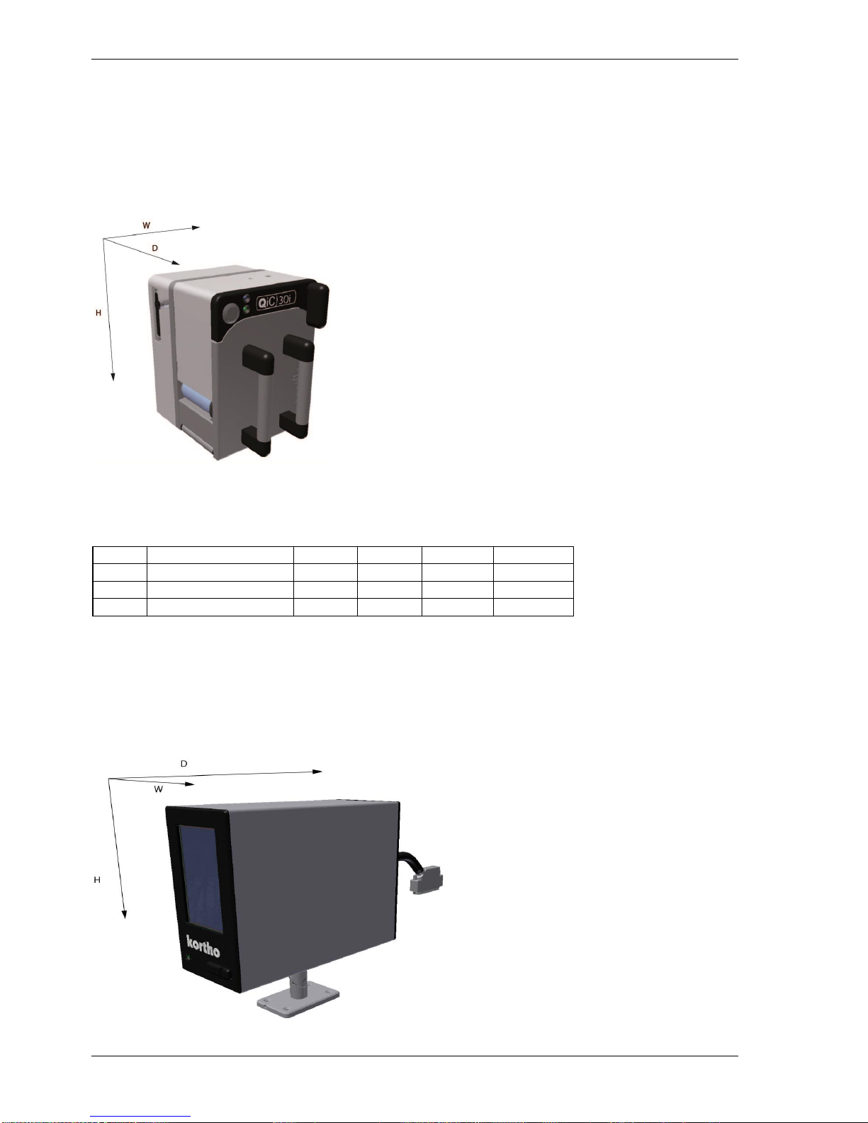
1.4.1 Coding unit
Fig. 1.1 Coding units, global dimensions
A general impression of the coding unit dimensions is given in Fig. 1.1. The dimensions (H x W x D) of the
coding units are (bracket excluded, see section 6.3.1 and 6.3.2 ):
Part.nr.
Printer
Height
Width
Depth
Print area
816629
Coding unit QiC 30i
196
166
192
53x30
816311
Coding unit QiC 53i
196
214
192
53x107
815722
Coding unit QiC 107i
196
214
244
107x107
The ambient temperature must be between 5 °C and 40 °C, with a relative humidity between 10% and 90%
(non-condensing).
Use only Kortho thermal transfer ribbon for this printer.
1.4.2 Control unit
Fig. 1.2 Control unit, global dimensions
INTRODUCTION
H325 IAE Rev.: 004 kortho QiC i-series
1-3
A general impression of the control unit TsC12 dimensions is given in Fig. 1.2. The dimensions (H x W x D)
of the control unit TsC12 are 186mm x 98mm x 239mm.
As the different printer type require different settings there is a control unit available for each type of coding
unit.
Part.nr.
Description
817332
Control unit TsC12, QiC 30i
818242
Control unit TsC12, QiC 53i
818255
Control unit TsC12, QiC 107i
The electrical requirements for the power supply of the 30i and 53i printers are:
Voltage rating: 100-120 / 200-240 Vac;
Frequency rating: 50 and 60Hz;
Current rating: 1,55A / 0,75A
Power rating: 150VAmax.
Fuse rating: 2x T3,15A 250Vac (slow acting).
The electrical requirements for the power supply of the 107i printers are:
Voltage rating: 100-120 / 200-240 Vac;
Frequency rating: 50 and 60Hz;
Current rating: 2A / 1A
Power rating: 200VAmax.
Fuse rating: 2x T3,15A 250Vac (slow acting).
All external equipment that is connected to the control unit interface must be double insulated to qualify the
whole installation as a separated extra-low voltage (SELV, Class II) system.
CAUTION:
Make sure the interface cable is no longer than 30m. Using a cable longer than 30m can cause EMC
interference.
The control unit has a bespoke hardware user interface, communication ports and host I/O-ports.
The ambient temperature must be between 5 °C and 40 °C, with a relative humidity between 10% and 90%
(non-condensing).
1.4.3 Ribbon
The ribbon supplied by Korthofah BV is specifically selected for the QiC i-series thermal transfer printers. It
guarantees an optimum print head protection and so print head life time in combination with an optimum
print result. In order to guarantee an optimum print result on each packaging material Korthofah BV
supplies a wide range of different ribbon types. In addition, ribbons are available in a variety of colours.
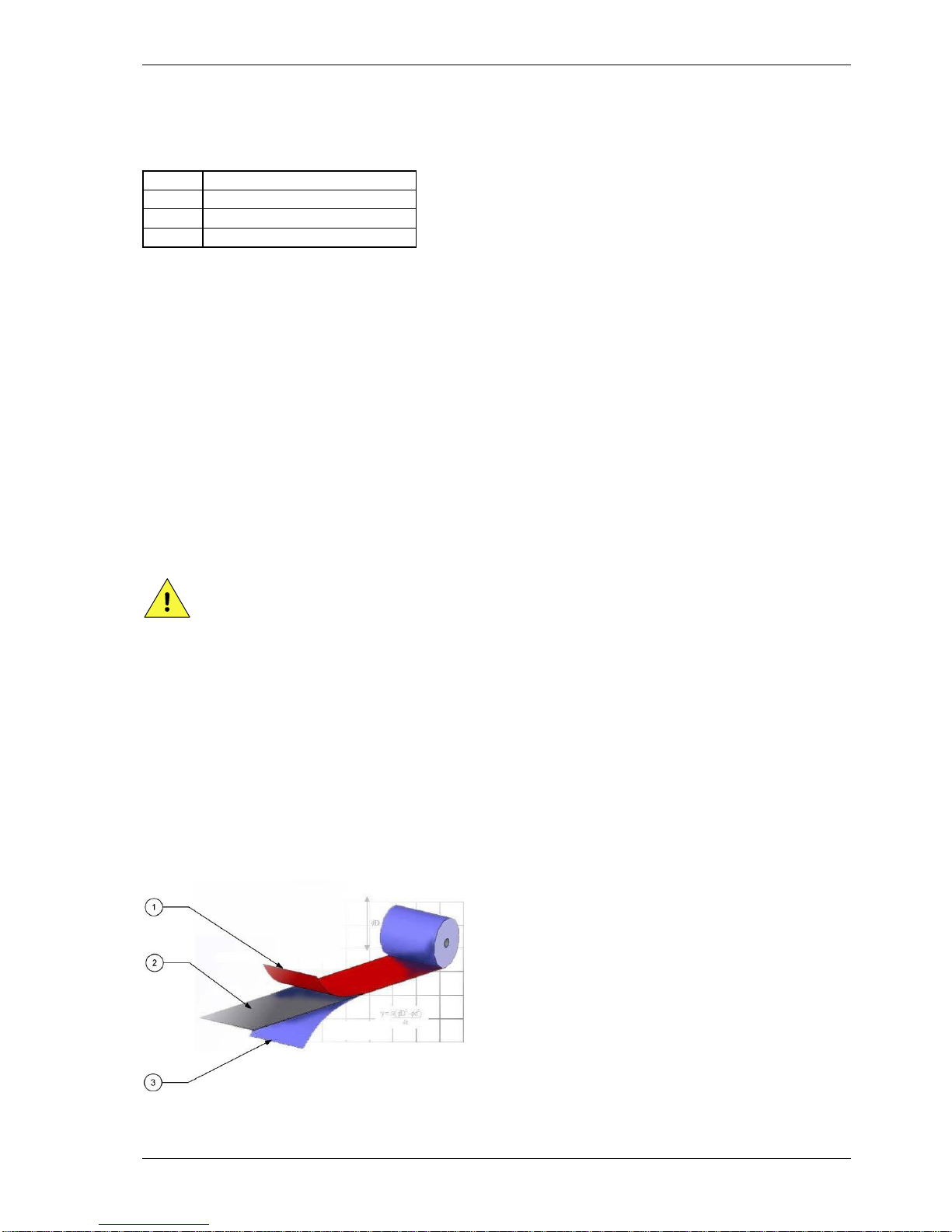
1. Back coating
2. Carrier film
3. Ink/pigment

INTRODUCTION
kortho QiC i-series H325 IAE Rev.: 004
1-4
Fig. 1.3 Ribbon
Ribbon is composed of three layers: Back coating, Carrier film and Ink.
The back coating contains extremely small beads of silicon which protect the sensitive printhead from
abrasion, provides excellent heat conductivity to enable the ink to transfer to the substrate and reduces the
formation of static electricity, which is harmful to the printer and its operator. Cheaper ribbons without this
protection layer can damage the printhead.
The polyester film carrier provides the mechanical stability ensuring the ribbon doesn’t break under the
stresses of acceleration yet allows the heat developed by the thermal printhead to be transferred into the ink.
The ink formulation balances wax and resins to produce the optimum print quality based upon printhead
technology, the substrate being printed, print speed and environmental conditions (e.g. ambient temperature
and humidity).
The thermal ribbon should be stored in a dark, dry and cool place.
The recommended ambient temperature while printing is between 10 °C and 30 °C.
1.4.4 Label features
Label:
Name: User defined name.
Test label: A label that is permanently available (cannot be deleted) and specifically designed
for making test prints to check the print quality and the correct setting of several
parameters.
Items: Text, multiple line text, number, date, time, shiftcode, barcode, line and box items
and graphic. These items are placed in a label with the label design software.
Data: Fixed and variable.
Size: Maximal 96kB.
Max. items: 7 number items per label. 1000 external or 400 internal characters per text item
(including check characters).
Font:
Internal: 6 fonts are preinstalled on the system; Liberation Sans, Liberation Serif, Tahoma,
Century Gothic, Arial black and ArabDigit Black. In addition extra fonts can be
stored. The system offers full downloadable font support for Windows TrueType
fonts. The font ArabDigit Black can only be used for Arabic digits, e.g. time, date and
numbers. The other internal fonts can be used to print fixed and variable text e.g.
time, date and operator input text, see section 9.1.3.
External: fonts used in a label but not installed on the system. External fonts will be treated as
fixed data/text. So if an external font is used in e.g. a time item, the system will start
printing the time at which the label has been loaded in the print memory, but will
not update it during the print process. I.e. the system will print the same time during
the complete production batch.
Barcode formats: Several barcode formats are available among which Codabar, Code 2 of 5, Code128,
Data Matrix, EAN128, EAN13, EAN8, RSS-14, UPC A. For a complete list see section
Appendix A. Barcodes will be printed as fixed items.
Items:
Graphic: In jpg, jepg or bmp format (black/white).
Dynamic: Number, date, time and shiftcode.
Operator input: Text, number, date.
Label download: Through Ethernet or a USB thumbdrive. Ethernet can be used to download a label to
the print memory. By using the USB thumbdrive a lot of labels can be copied to the

INTRODUCTION
H325 IAE Rev.: 004 kortho QiC i-series
1-5
label memory. While selecting a label for printing the label will be transferred form
the label memory to the print memory. The print memory can only hold one label.
Storage capacity: 55MB (approximately 570 labels of the maximum label size).
1.4.5 Life span
The life span of the equipment is five years, except for the printhead, under normal use and in compliance
with the indicated maintenance periods.
The life span can be negatively influenced by improper/uninformed use of the equipment or improper
maintenance, repair or modification by unqualified personnel, or repair with non-original parts. No claims
for guarantee or compensation for damages will be accepted in such instances.
1.4.6 Electrostatic charge
Make sure that the substrate is not able to build up an electrostatic charge near the printhead, i.e. use
conductive rolls and bearings for substrate guidance, place an ESD brush or an ionizing air bar just before
the printer.
An electrostatic charge will disturb the print by electrostatic influence on the printhead, this may cause
permanent printhead failure.
1.4.7 Shock & vibration
The printer should be installed on a low vibration location.
It is recommended that the coding unit is protected from shock and vibration, as this will have severe impact
on the printed label quality and printhead life.

INTRODUCTION
kortho QiC i-series H325 IAE Rev.: 004
1-6
H325 IAE Rev.: 004 kortho QiC i-series
2-1
2 TECHNICAL DESCRIPTION
This section is meant for all users. It describes all the main parts of the printer system.
2.1 The printer system
Fig. 2.1 The printer system
A typical thermal transfer system is shown in Fig. 2.1. The substrate is placed on an intermittent packaging
machine and passes between the coding unit and the platen. As the substrate stops moving, the printer
receives a print-request signal from the host machine or print sensor and the selected label will be printed on
the substrate.
The thermal printhead receives the label line by line from the buffer memory and prints it on the substrate.
The resolution is always 12 dots/mm (300 DPI) in width and, when the substrate is not moving while
printing, 12 dots/mm (300 DPI) in length.
While the printhead returns to his home position the label variables will be updated.
After printing a label the printer is in stand-by mode again and awaiting the next print request signal.
After receiving the next print request signal the time and date items will be updated after which the system
will print the completely updated label.
The coding unit is connected to the control unit. All connections between printer and peripheral devices are
made on the control unit i.e. print request signal, alarm signals and Ethernet connection.
1. Coding unit
2. Platen
3. Frame
4. Substrate
5. Control unit (not shown)
TECHNICAL DESCRIPTION
kortho QiC i-series H325 IAE Rev.: 004
2-2
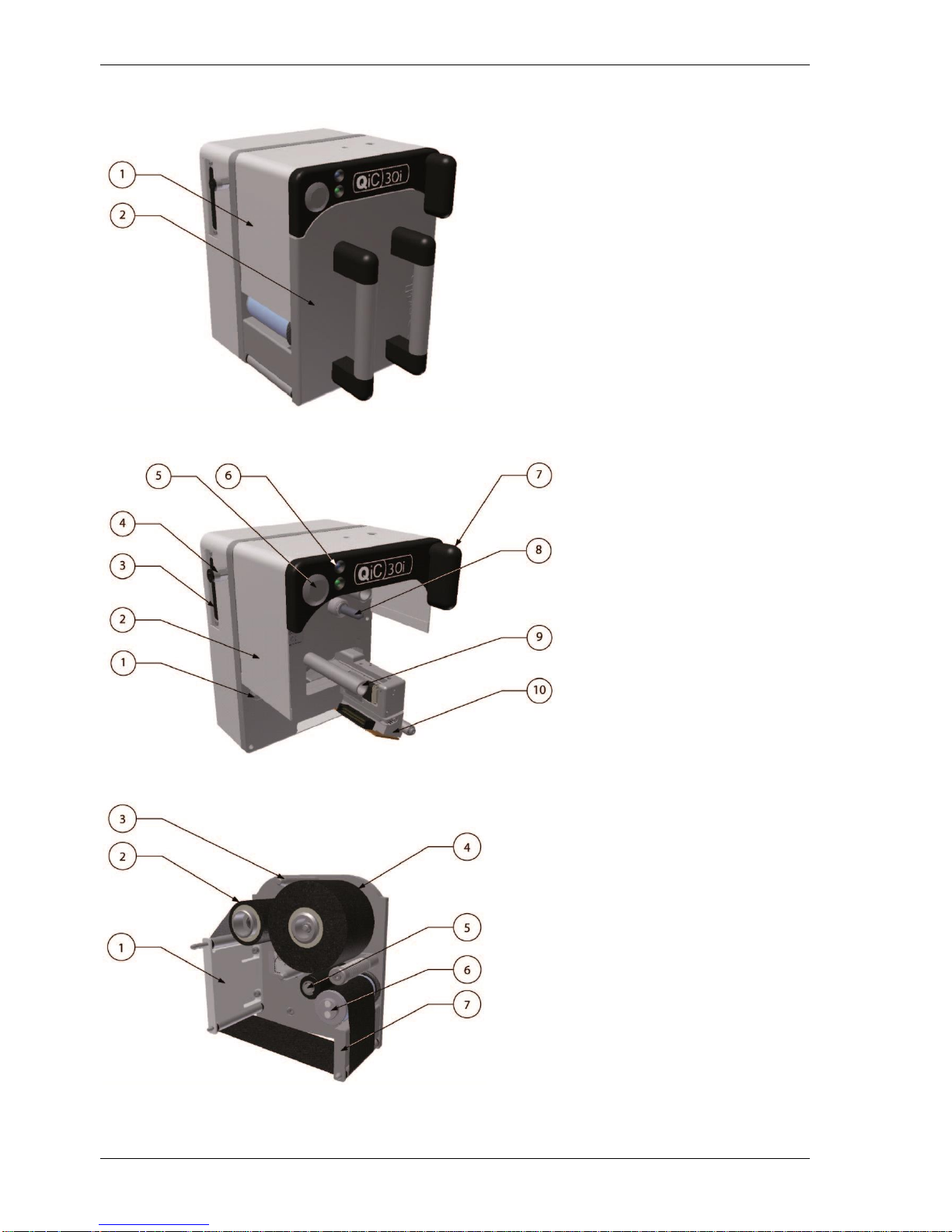
2.2 Coding unit
Fig. 2.2 Coding unit, parts
Fig. 2.3 Coding unit, interior parts front
Fig. 2.4 Magazine, parts
1. Printer body
2. Magazine
1. Ribbon movement sensor
2. Finger guard
3. Connection to control unit
4. Connection to air supply
5. Front button (S)
6. Status LED
7. Magazine handle
8. Magazine ribbon drive
9. Magazine guide
10. Printhead
1. Finger guard
2. Used ribbon
3. Guide post
4. New roll of ribbon
5. Pressure roller
6. Ribbon sensor roller
7. Finger guard
TECHNICAL DESCRIPTION
H325 IAE Rev.: 004 kortho QiC i-series
2-3
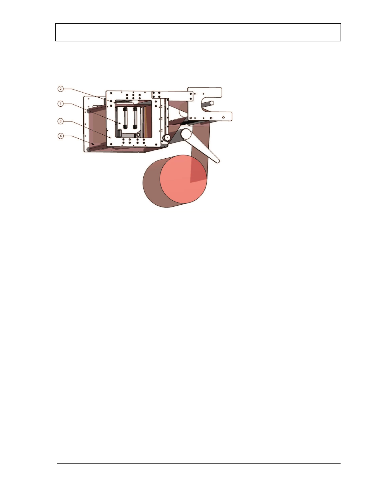
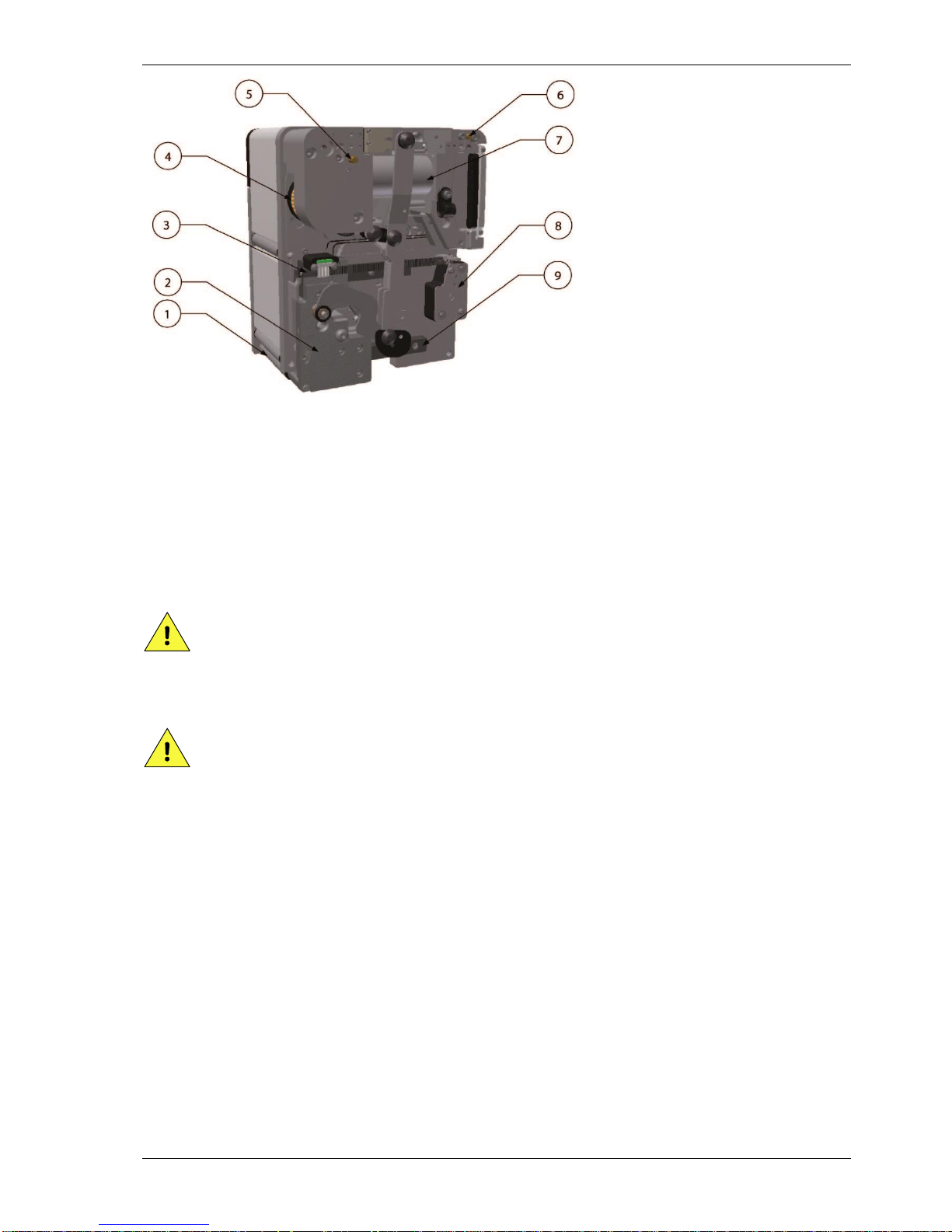
Fig. 2.5 Coding unit, interior parts back
The coding unit comprises several key components.
The printer body contains all the mechanical and sensors necessary to drive the printhead and index the
ribbon. The printer body connects to the control unit and supports the magazine.
The magazine is fitted to the printer body and guides the ribbon during printing. It is easily removed and
stable when placed on a flat surface during ribbon changes.
CAUTION:
Do not place any your fingers in the opening in the main plate of the coding unit once the
magazine has been removed. This as there is a small change one cuts oneself on sharp edges on
parts inside the coding unit and there is a very small change one becomes trapped due to moving
parts inside the coding unit.
CAUTION:
Be careful when touching / exchanging the printhead. The printhead could be very warm and has some
sharp edges on which one can cut oneself.
If required a spare magazines can be used for very fast changeovers (e.g. during a production run).
1. Peel-off roller
2. Printhead carriage
3. Encoder strip
4. Clutch
5. Return speed adjustment
6. Print speed adjustment
7. Carriage drive cylinder
8. Ribbon encoder
9. Rail plate
TECHNICAL DESCRIPTION
kortho QiC i-series H325 IAE Rev.: 004
2-4
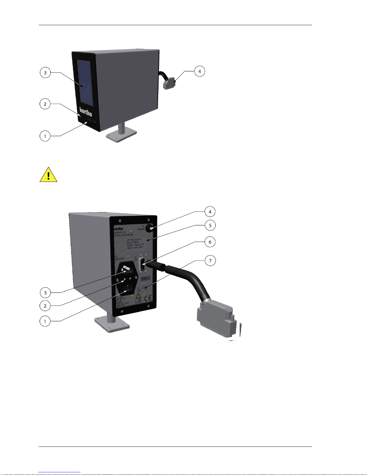
2.3 Control unit
Fig. 2.6 Control unit + adjustable support
CAUTION:
Do not use an extension cable for connecting the USB thumbdrive to the control unit, but place the
USB thumbdrive directly in the control unit. Using an extension cable can cause EMC interference.
Fig. 2.7 Control unit, connections
2.4 Air supply
The printer requires an air supply that is clean and dry (ISO 8573-1:2010 [4:4:3]). The air pressure should be
set to 0,4 MPa (4 bar) for the QiC 30i and 53i and to 0,5 MPa (5 bar) for the QiC 107i.
1. USB connection
2. Pre-heat status LED
3. Touch screen
4. Printer data/power cable
1. Switch Mains power
2. Mains fuses
3. Mains supply (X1)
4. Pre-heat fuse (F1)
5. Serial no. label
6. Interface connector (X3)
7. LAN connector (X2)
TECHNICAL DESCRIPTION
H325 IAE Rev.: 004 kortho QiC i-series
2-5
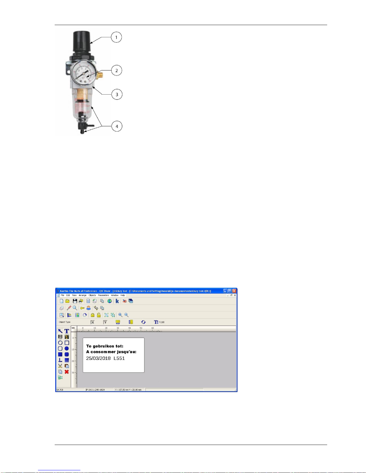
Fig. 2.8 Air regulator
2.5 Label design
A label can be designed by QiC Draw or NiceLabel in combination with the Windows driver. Other software
can be used in combination with the Windows driver, but depending on the software, most internal label
functions will not be available. Please consult Korthofah or your local distributor for further information.
2.5.1 QiC Draw label design software
The label design software is called QiC Draw.
With this software package one can create labels for the QiC printer series. Besides the label design options,
the program also offers several service diagnostic tools. It runs on an IBM-compatible PC with Microsoft
Windows NT, 2000, XP, 7 or 8 installed.
For full details on installing and using the package, see the separate QiC Draw manual.
Fig. 2.9 QiC Draw main window
1. Pressure regulator
2. Pressure gauge
3. Air distribution manifold
4. Water separation bowl with
a manual drain valve

TECHNICAL DESCRIPTION
kortho QiC i-series H325 IAE Rev.: 004
2-6
2.5.2 NiceLabel
Labels can also be created by using NiceLabel or any other windows based program using the Kortho
printer driver for NiceLabel. When using this driver in combination with the NiceLabel software one can use
the full options this software program offers including variable text and data fields. One should note that
using the NiceLabel Windows driver in combination with any other program will limit the label item
options to fixed items. For information about the installation of the driver and the use of the NiceLabel, see
Appendix E.

H325 IAE Rev.: 004 kortho QiC i-series
3-1
3 PRINT PROCESS DESCRIPTION
3.1 Print cycle
The purpose of the printer is to print a label on a substrate. A label is digital data and is stored in the print
memory of the control unit. The control unit converts the label into a bitmap. The printhead receives this
bitmap pixel-column by pixel-column and uses it to fire the heating elements of the printhead.
The ribbon that is placed between the printhead and the substrate is heated by the printhead heating
elements. While a heating element is hot, the pigment of the locally heated ribbon will be transferred onto
the substrate. By firing the heating elements in the right sequence the selected label will be printed on to the
substrate.
The printhead contains 640 heating elements (12 dots per mm at a printhead width of 53,3mm). The vertical
resolution is controlled by a linear encoder that is linked to the printhead carriage. The resolution of this
encoder is also 12 dots per mm.
The print cycle is initiated with a “print request” signal. The print request signal can e.g. be generated by a
spot photocell, a relay switch or a PLC inside the host machine.
Once the print request signal is received by the control unit, the following sequence will be started:
1. Printhead down.
2. Printhead carriage forward.
3. Firing of the heating elements in the sequence determined by the label bitmap.
When the print is completed:
4. Printhead up.
5. Printhead backwards (ribbon will be transported at the same time).
When enough ribbon has been transported to make the next print on unused new ribbon:
6. Clutch will be activated (ribbon transport will stop).
When the printhead is back in its home position:
7. Pressure will be taken of the carriage drive cylinder.
8. Clutch will be deactivated.
When a print has been made, the bitmap will be updated, if necessary, for variable label items such as time,
date and number items. When this is done, the Busy output is de-activated and the printer is ready for the
next print request.
3.2 Printhead
The printhead has high productivity and reliability by using its unique face-down IC bonding method
instead of the conventional wire bonding method. It is seen in a range of industrial coding and marking
applications, as a versatile technology able to print on a wide variety of substrates.
The printhead consists of an alumina ceramic base plate. This base plate is covered by a glass layer, a heater
line layer and finally an abrasion-resistant ceramic coating. The structure and materials chosen guarantee a
high quality print and an optimal life time of the printhead.

PRINT PROCESS DESCRIPTION
kortho QiC i-series H325 IAE Rev.: 004
3-2
For making a high quality print with the printhead it is important that:
The right amount of energy is applied to the heating elements (customer setting).
The pre-heat is set to the optimum value (customer setting).
The printhead, with the ribbon and substrate in between, is pressed against a platen with the right
force (factory pre-set).
The ambient temperature is between 5 °C - 40 °C (41 °F - 104 °F).
The ribbon and the substrate are matched. Various ribbons are available each with its own specific
characteristics.
The environment and especially the substrate is clean. Some materials, like small hard particles, can
damage the printhead. Due to this white lines will appear in the print. This type of damage is
permanent.
The printhead maintenance, refer to section 10.1.1. Important factors in regards to this are:
o Abrasion: the process of wearing down by friction—will occur during normal operation of the
printer. However, it can be minimized through proper care and maintenance and by using a
high quality ribbon.
o Contamination: when particulate matter—such as dust—damages the printhead, it becomes
contaminated.
o Corrosion: Gradual deterioration of the printhead may occur because of the substrate being
used, incorrect cleaning agents or the environment.
o Electrostatic Discharge (ESD): Electrostatic discharge may occur due to improper handling,
charging of non-conductive substrate and ribbon moving through dry air.
o Moisture: If your printer is operating in a humid or damp environment, this moisture may
damage the printhead.
o Residue: The build-up of residue—or foreign materials—may occur with improper
maintenance, incorrect cleaning agents, inferior substrate or incorrect application setup.
Aggressive cleaning requires the use of Kortho’s specially-formulated cleaning swabs.
3.3 Coding unit
The coding unit can be positioned in almost any position. When positioning the system it is important to
take the following issues into account:
The magazine should face the operator for easy access and clear view on the indicators.
Print in the opposite direction of the substrate movement. This makes sure the substrate will not
move during the print process.
When printing in a vertical position, it is preferable to print upwards.
3.4 User interface
The user interface on the control unit consists of a touch panel displaying the menu structure of operator
menus and a LED indicator showing whether the system is preheating the printhead. Beside this, a
multifunctional button (test print/ reset error/reset ribbon length) and 2 LED indicators are present on the
coding unit.
The touch panel consists of a resistive touch screen and a TFT panel. For accurate operation it is important to
apply the pressure on a relatively small area e.g. by using a stylus. To prevent using a stylus all the time, the
user interface has been optimized for finger touch.
PRINT PROCESS DESCRIPTION
H325 IAE Rev.: 004 kortho QiC i-series
3-3
3.4.1 Menu structure
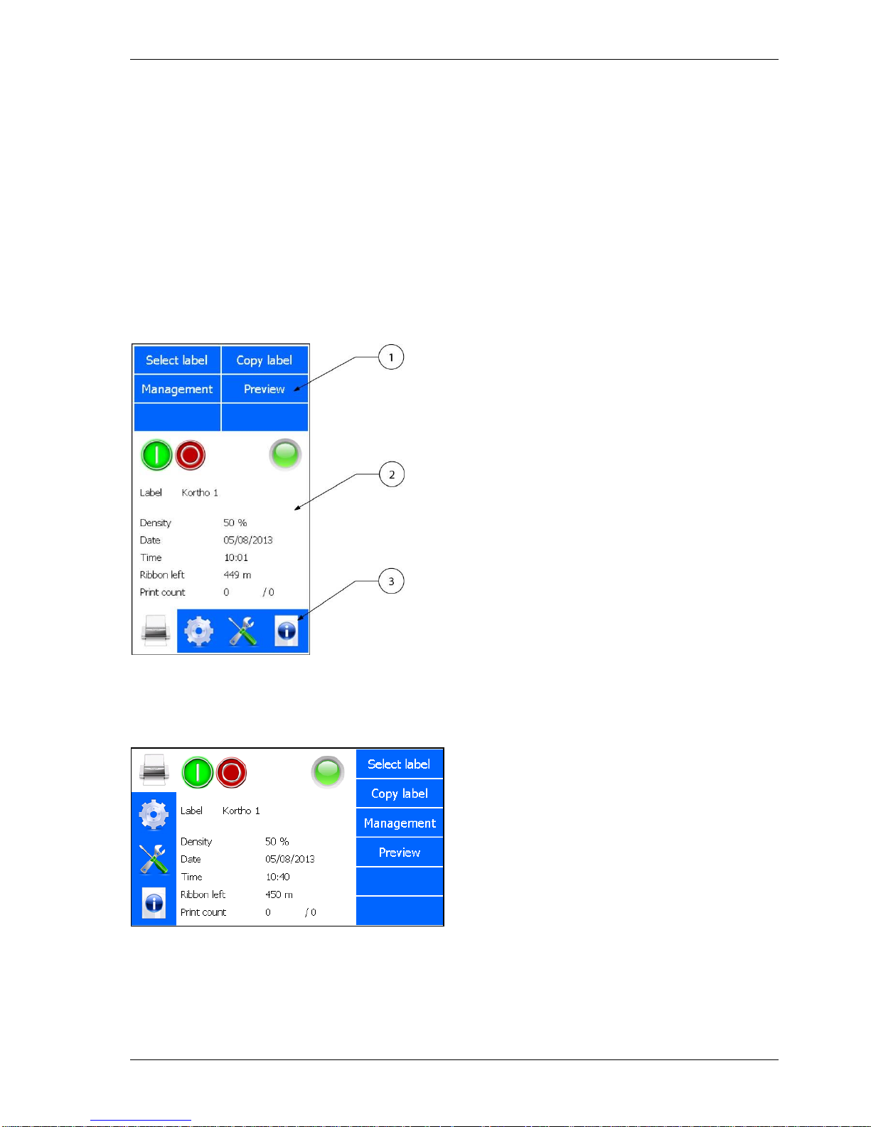
The screen is divided in three parts, see Fig. 3.1. Section 1 shows the submenus available when the printer
icon is selected. When the other icons in section 3 are selected, different submenus will be shown. Section 2 is
showing the status of the printer and the Start (I) \ Pause (0) button. Depending on the button selected in
section 1 and 3 the content of this section will change.
The content can be settings, status information or general information. Section 3 is showing the 4 main menu
options:
1. Label selection/Label management.
2. Printer settings.
3. Diagnostics.
4. Information.
Fig. 3.1 Screen layout, main menu portrait
The standard factory setting for the menu is portrait mode. Alternatively the screen can be displayed in
landscape mode. The screen can be rotated by steps of 90 degrees, see section 8.6.1.
Fig. 3.2 Screen layout, main menu landscape
1. Section 1, sub menu items
2. Section 2, status, options and
preview area
3. Section 3, main menu items

PRINT PROCESS DESCRIPTION
kortho QiC i-series H325 IAE Rev.: 004
3-4
3.4.2 LED indicators on control unit
The status screen of the control unit shows a LED indicator which is showing the same as the status LED on
the coding unit, see section 3.4.3.
The green LED indicator, on the front bottom left corner of the control unit enclosure, indicates whether the
heating element for preheating the printhead is energised (heating). When starting up the printer, the LED
will light continuously.
When at temperature, the LED will start flashing. If the LED remains off during printing, the temperature of
the printhead is above the set temperature of the preheat setting.
The thermal printhead produces heat, so if the system is printing a lot, the printhead will be heated by the
energy it produces and the preheating system simply shuts down.
3.4.3 LED indicators and front button on coding unit
There are two LED indicators and a single front button (S) mounted on the coding unit. This is particularly
useful for operators during the replacement of ribbon or solving a ribbon break as all the necessary controls
are located above the magazine.
Fig. 3.3 LED indicators and front button
The front button has several functions:
1. Following a ribbon break, printer malfunction or head being lifted: pressing the front button (S) will
attempt to reset the condition. However, if the condition remains e.g. the ribbon breakage is not
recovered, then the button will not reset the printer.
2. If the printer is ready to print i.e. label loaded, head locked and no printer fault: pressing the front
button will trigger a single print when the system is set in pause mode.
3. After placing a new roll of ribbon: pressing and holding the front button for about 4 seconds will
reset the ribbon left value to the length of a full roll.
4. After a firmware update or if the system is not responding properly: pressing the front button while
switching on the printer will reset most of the variables to the factory setting. To reset the control
unit:
1. Press front button (S).
2. Switch on the control unit and keep front button pressed
3. When the status led starts flashing, release the front button.
The Power LED shows if the 5VDC is present in the coding unit
The Status LED displays several conditions:
Constant green: System ready for printing.
Blinking green: No label loaded.
Fast blinking green: Internal data communication activity.
Constant orange: Ribbon break, head unlocked or printer fault.
Blinking orange: Low ribbon warning.
Blinking red/orange: System reset.
1. Front button (S)
2. Power LED (bleu)
3. Status LED (green/orange)
PRINT PROCESS DESCRIPTION
H325 IAE Rev.: 004 kortho QiC i-series
3-5
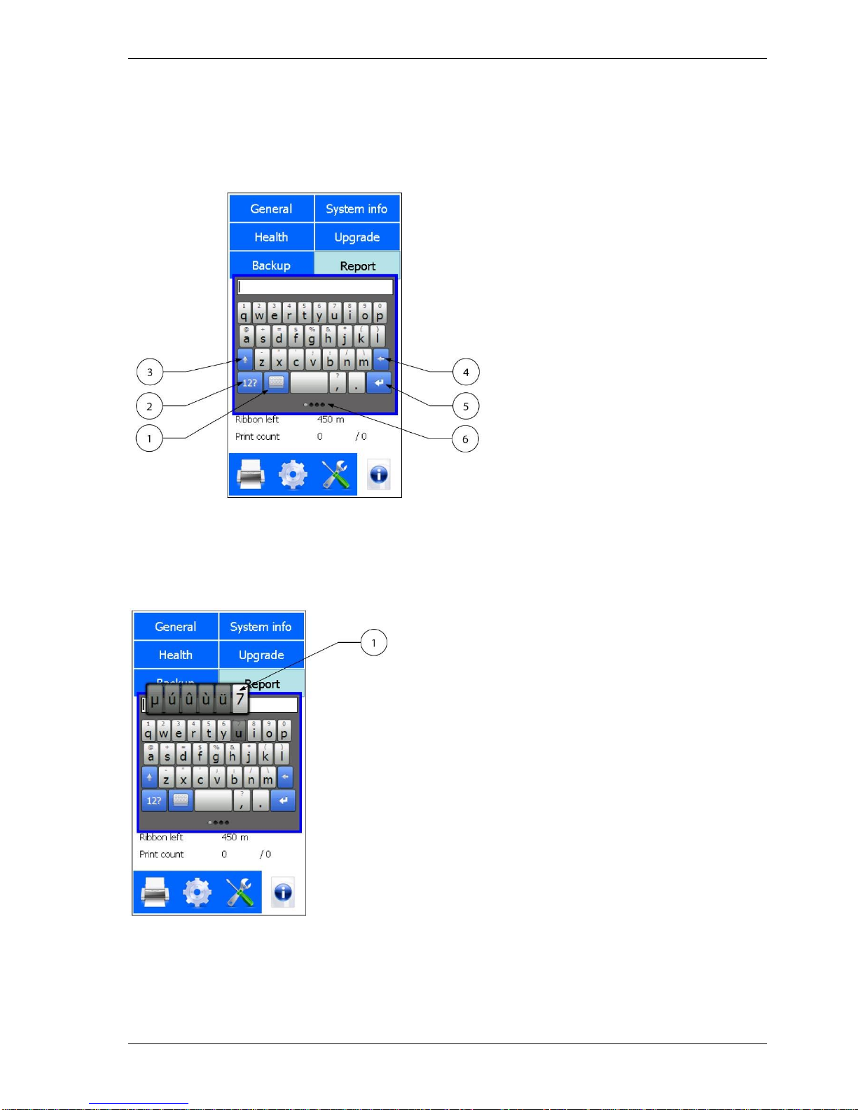
3.4.4 Keyboard
Data and settings can be entered through a keyboard that will be displayed on the TFT panel.
The keyboard has four screens. The first screen is shown below. The tiny round indicators at the bottom of
the screen show which of the four keyboard screens is currently displayed. One can select another keyboard
by either using the relevant buttons or by swiping over the round indicators at the bottom of the screen.
Fig. 3.4 First keyboard screen
To use the keyboard superscript alphanumerics:
1. Touch and hold the desired key.
2. Drag your finger to the left or right to select the character of choice.
Fig. 3.5 First keyboard screen, alternative alphanumerics
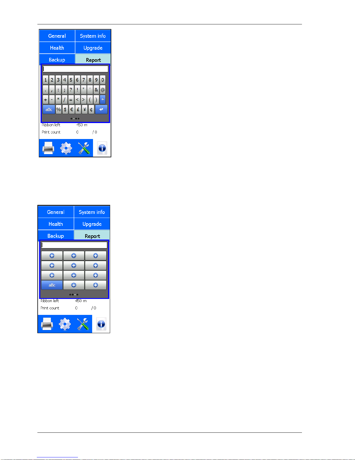
An alternative way to select a digit is to touch the numeric and special characters button. The second
keyboard screen will appear.
1. Special functions button
2. Numeric and special characters
button
3. Shift
4. Backspace
5. Enter
6. Round indicators
1. Alternative alphanumerics
PRINT PROCESS DESCRIPTION
kortho QiC i-series H325 IAE Rev.: 004
3-6
Fig. 3.6 Second keyboard screen, numeric and special characters
For entering commonly used text the third keyboard screen can be used. One can store frequently used texts
in this keyboard. To enter this screen either swipe over the round indicators at the bottom of the screen or
touch the special functions button in the first screen to enter the fourth screen and touch FX.
Fig. 3.7 Third keyboard screen, commonly used text
To program the buttons in the third screen:
1. Touch the special functions button on the first keyboard screen.
2. Touch the FX button.
The screen as shown in Fig. 3.7 will appear.
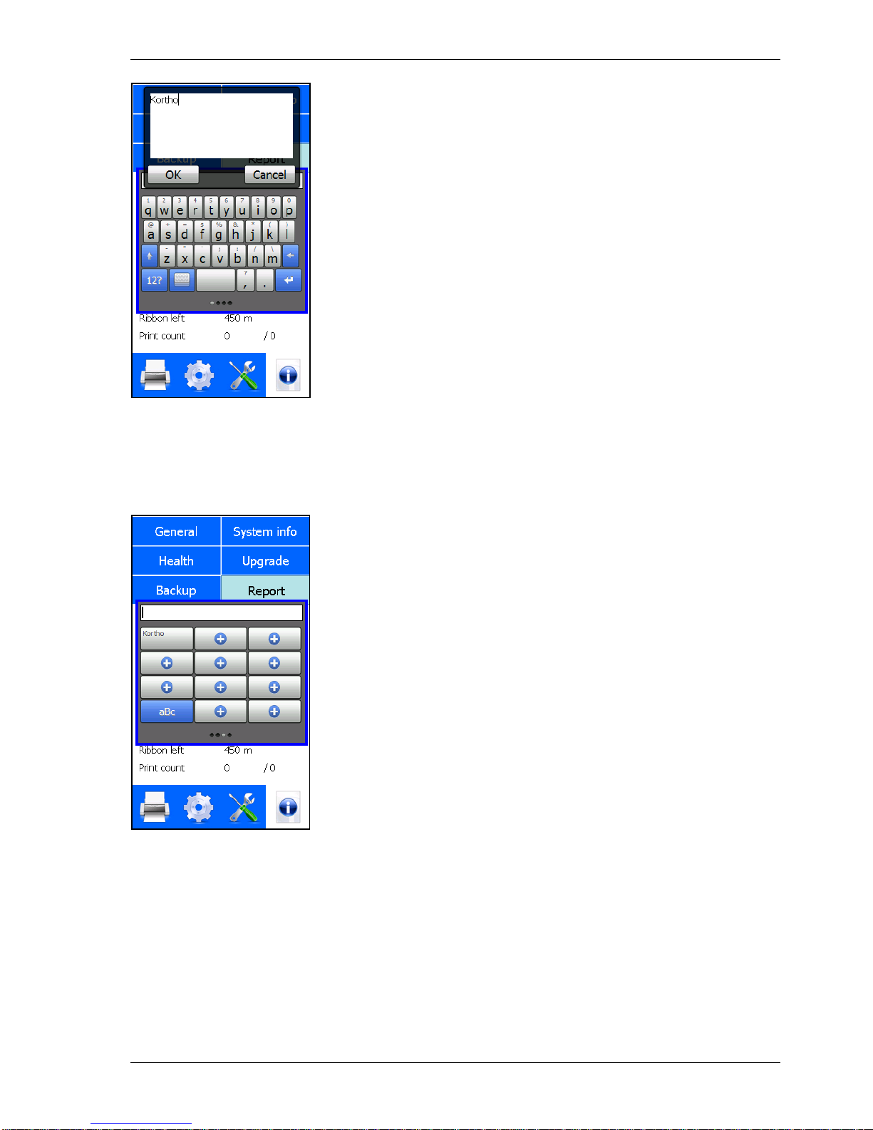
3. Touch one of the + buttons and enter the data to be stored (only one line can be stored), see Fig. 3.8.
PRINT PROCESS DESCRIPTION
H325 IAE Rev.: 004 kortho QiC i-series
3-7
Fig. 3.8 Programming third keyboard screen buttons, entering text
4. Touch the OK button to store the text.
The button is now labelled with the text entered, see Fig. 3.9. Touching this button enters the text where
required.
Fig. 3.9 Programming third keyboard screen buttons, entering text
The text in a button can be deleted or modified later on.
A text placed by using the third keyboard screen will be treated as normal text, so the text can be deleted or
modified if required.
PRINT PROCESS DESCRIPTION
kortho QiC i-series H325 IAE Rev.: 004
3-8
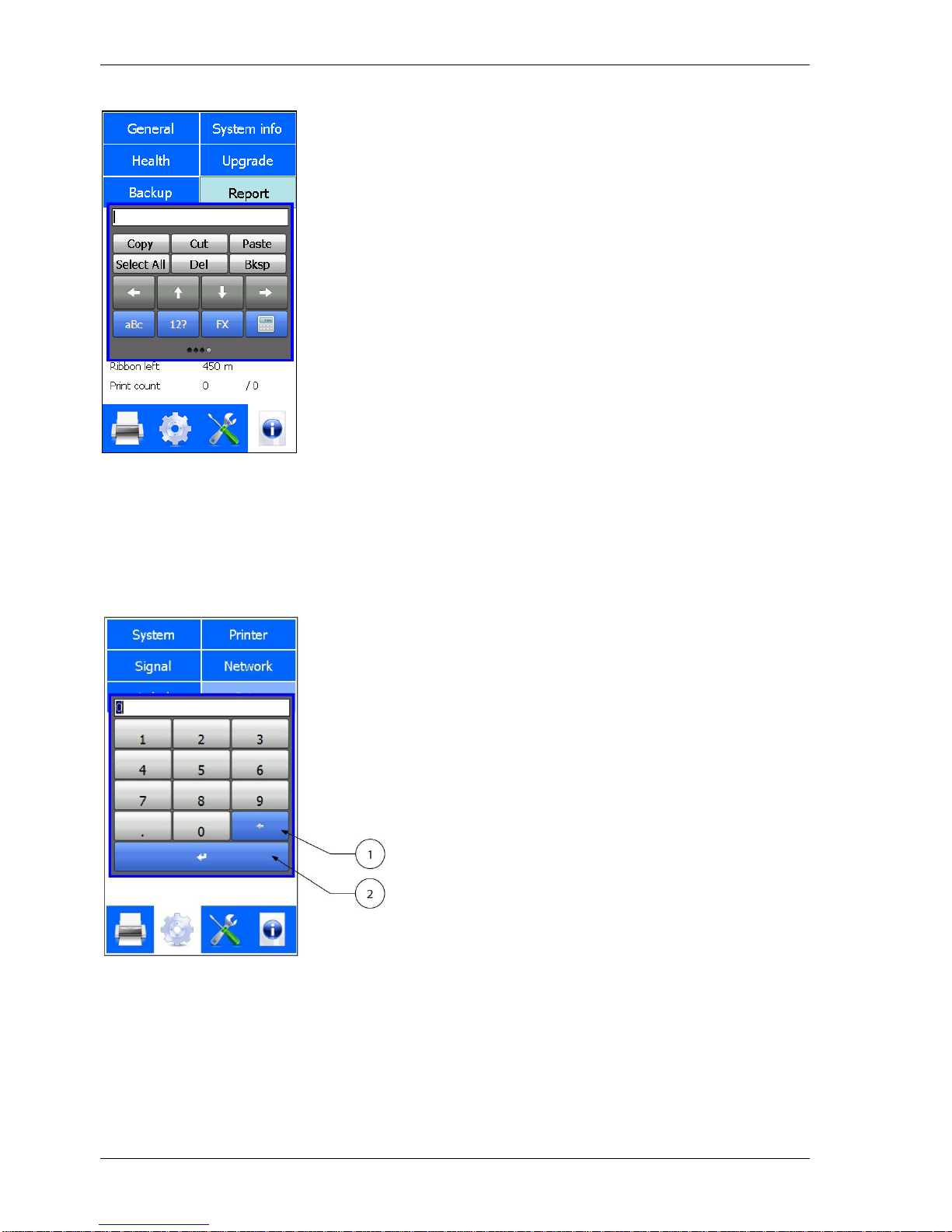
To edit text and use cursor controls, touch the keyboard button. This following screen will appear:
Fig. 3.10 Fourth keyboard screen, edit text and use cursor controls
To return to the first screen touch the aBc button.
To return to the second screen touch the 12? button.
To return to the third screen touch the FX button.
Beside the standard keyboards there is a numeric keyboard available for all numeric items/entries, see figure
Fig. 3.11.
Fig. 3.11 Numeric keyboard
1. Backspace
2. Enter
PRINT PROCESS DESCRIPTION
H325 IAE Rev.: 004 kortho QiC i-series
3-9
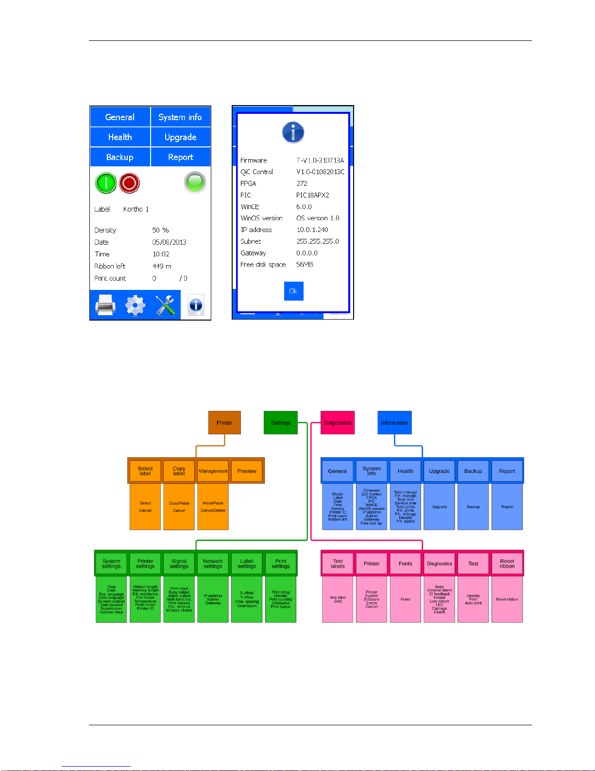
3.4.5 System information
The firmware versions installed on the control unit can be displayed on screen by pressing System Info in the
Information menu.
A B
Fig. 3.12 Entering the System information screen
3.4.6 Menu structure
Fig. 3.13 Standard menu structure
Refer to Appendix F for a full-scale sheet of the menu structure.

PRINT PROCESS DESCRIPTION
kortho QiC i-series H325 IAE Rev.: 004
3-10
 Loading...