

Kortek KT-1982F, KT-1782DF, KT-2182F, KT-1982DF, KT-1782F Service Manual
SERVICE MANUAL
COLOR CRT MONITOR
KT-1982F / KT-1982DF
KT-1782F / KT-1782DF
KT-2182F
KORTEK CORPORATION
DOC. NO KT-XX82X-SM
DATE 2004 .02. 02
REV. NO 0
REV. DAT E -

- 2 -
1. PRECAUTIONS -------------------------------------------------- 3
2. PRODUCT SPECIFICATION -------------------------------- 6
3. OPERATING INSTRUCTION -------------------------------- 9
4. ADJUSTMENTS ------------------------------------------------- 11
5. TROUBLE SHOOTING GUIDE ---------------------------- 19
6. PART LIST ------------------------------------------------------- 29
7. BLOCK DIAGRAM --------------------------------------------- 34
8. CONNECTING DIAGRAM ----------------------------------- 35
9. SCHEMATIC ----------------------------------------------------- 36
10. PRINT CIRCUIT BOARD ---------------------------------- 38
CONTENTS

- 3 -
1-1. Safety precautions
Warnings :
Service should not be attempted by anyo ne unfamiliar with the
necessary on this Monitor.
The followings are the necessary precautions to be observed before servicing.
1) For continued safety, do not attempt to modify the circuit board.
2) Disconnect the AC power before servicing.
3) When the chassis is operating, semiconductor heat sinks are potential
shock hazards.
1-1-1 Servicing the high voltage volume are CRT Warnings
A High Voltage volum e replaced in the wrong direction may cause excessive
X-Ray emissions.
1) Adjust in order to 26KV with signal at Anode.
2) When the troubleshooting a monitor with excessively High Voltage, avoid
being unnecessarily close to the monitor. Do not operate the monitor for
longer than is necessary to locate the cause of excessive voltage.
3) Excessive High Voltage can produce potentially hazardous X-Ray RADIATION. To avoid such hazards, the high voltage m ust be above the
specified lim it. The nominal value of the High voltage of this Monitor is
26KV±0.3KV at zero beam current(m inimum brightness) under a 120V
AC power source. The High Voltage must not (under any circum stances)
exceed 29KV. Each tim e a monitor requires servicing, the High Voltage
should be checked following the High Voltage check procedure on this
manual. It is recommended the reading of the voltage be recorded as a
part of the service record. It is im portant to use an accurate and reliable
High Voltage meter.
4) When the High Voltage regulator is operating properly, there is no possibility of an X-Ray problem.
5) The CRT is especially designed to prohibit X-ray emission. To ensure
continued X-ray protection, replace the CRT only with one that is the
sam e or equivalent type as the original.
6) Handle the CRT only when wearing shatterproof goggles and after completely.
7) Do not lift the CRT by the neck.
1.Precautions
- 4 -
1-1-2. Fire and Shock Hazard
Before returning the monitor to the user,perform the following safety checks:
1) Inspect each lead dress to make certain that the leads are not pinched or
that hardware is not lodged between the chassis and other metal parts
in the monitor.
2) Inspect all protective devices such as nonm etallic control knobs, insulating
materials, cabinet backs, adjustment and com partment cover or shields
isolation resistor-capacitor networks, m echanical insulations, etc.
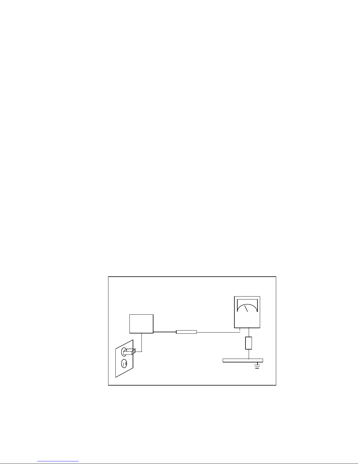
3) To be sure that no shock hazard exists, check for leakage current in the
following manner.
a. Plug the AC line cord directly into a 120 or 230 Volt AC outlet.
(Do not use an isolation transformer for this test)
b. Using two clip leads, connect a 1.5KΩ, 10Watt resistor paralleled by a
0.15Uf capacitor in serial with an exposed metal chassis part and a
known earth ground, such as an electrical conductor and electrical
ground connected to a earth ground.
c. Use a SSVM or VOM with 1000 ohms per-volt or sensitivity to measure
the AC voltage drop across the resistor.
d. Connect the resistor to an exposed metal part having a return path to
the chassis(m etal cabinet, screw heads, knobs, shafts, escutcheon,etc)
and measure the AC voltage drop across the resistor.
e. Any reading of 5.25 volt RMS(this corresponds to 3.5 milliampere AC)
or more is excessive and indicates a potential shock hazard. Correct
the shock hazard before returning the monitor to the user.
Figure 1-1. Leakage Current Test Circuit
LEAKAGE
CURRENT
TESTER
(READING SHOULD)
NOT BE ABOVE
0.5m A
TEST AL L
EXPOSED METAL
SURFACES
DEVICE
UNDER
TEST
2-WIRE
CORD
ALSO TEST WITH
PLUG REVERSED
(USING AC ADAPTER
PLUG AS REQUIRED)
Earth
ground

- 5 -
1-1-3. Product safety notices:
Some electrical and mechanical parts have special safety related characteristics
which are often not evident from visual inspection. The protection they give
may not be obtained by replacing them with components rated for higher voltage,wattage,etc. Parts that have special safety characteristics are identified by
△
on schematics and parts lists.
A substitute replacement that does not have the sam e safety characteristics
as the recommended replacement part might create shock, fire and or other
hazards. Product safety is under review continuously and new instructions
whenever appropriate.
1-2. Servicing Precautions
WARNING 1 : First read the "Safety Precaution" section of this manual. if
unfo reseen circumstances create conflict between the servicing
precautions and safety precautions,always fo llow the safety
precautions.
WARNING 2 : A High Voltag e volume replaced in the wrong direction may
cause excessive X-ray emissions.
WARNING 3 : An electrolytic capacitor in stalled with the wrong polarity might
explode.
1) Servicing precautions are printed on the chassis, and should be followed
closely
2) Always unplug the units AC power cord from the AC power source before
attempting to :(a) remove or reinstall any component or assem bly, (b)
disconnect PCB plugs or connectors,(c) connect all test com ponents in
parallel with an electrolytic capacitor.
3) after servicing, always check that the screws, components and wiring have
been correctly reinstalled. Make sure that the area around the serviced
part has not been dam aged.
4) Check the insulation between the blades of the AC plug and accessible
conductive parts(examples:m etal panels,input terminals and earphone jacks).
5) Never defeat any of the +B voltage interlocks. Do not apply AC power to
the unit(or any of its assemblies) unless all solid-state heat sinks are
correctly installed.
6) Always connect a test instruments ground lead to the instrum ent chassis
ground before connecting the lead; always remove the instruments lead last.
- 6 -
2-1 SPECIFICATION
2. Product Specifications
CDT
Display Area (mm)
Bandwidth Maximum 140MHz
Scanning Frequency
(Auto Scanning)
Horizontal
Vertical
30-82KHz
50-120Hz
Microprocessor User Saving Mode 13 M odes
User Control
Display
Digital
Language
Position,Size,Pincushion,T rapezoid,H/Vcorner,
Pin-B,Trapezoid,Parallel,Tilt,Moire,Zoom
Color T emperature,Recall,Manual Degauss
Eng/Ger/F ra/Esp/Port
Display color Color T emperature 9300°K, 6500°K, User Color
Resolution Maximum M ode 1280 X 1024 @ 75Hz
Signal Input Connect 15 pin D-sub(Fem ale) or Option
Safety & EMC
Safety
EMC
UL,CSA,TUV,CB,DHHS
FCC,CE
Power Voltage AC 90-264V, 60 / 50±3Hz
Power Consumption Nomal Operation
Input Current
at 120V
Input Current
at 240V
≤
100 Watts
Operating :≤1.5Amps rms.
Turn on :≤30Amps Peak.
Operating :≤0.8Amps rms.
Turn on :≤60Amps Peak.
Linearity Cross Pattern
Horizontal : 5%
Vertical : 5%
Environment
Temperature
Humidity
Operating : 0 to +40
℃
Storage : -40 to +60
℃
Operating : 10 to 85%
Storage : 5 to 95%
KT-1982F KT-1982DF KT-1782F KT-1782DF KT-2182F
Tu be
19"Normal flat 19"Dyna flat 17"Dyna flat 17"Normal flat 21"Normal flat
Tu be Size(Diagonal)
494.8mm 494.8mm 444.0mm 444.0mm 548.0mm
Viewable Size(Diagonal) 457.2mm 457.2mm 406.7mm 401.0mm 508.0mm
Dot Pitch
0.26㎜(H) 0.25㎜(H) 0.25㎜(H) 0.28㎜(H) 0.25㎜(H)
Deflection Angle
90
°
90
°
90
°
90
°
90
°
Fo cusing Method
Double Double Double Double Double
Norm al (H*V)
360*270 360*270 320*240 320*240 400*300
Maximum (H*V)
370*278 370*278 330*248 330*248 410*308
- 7 -
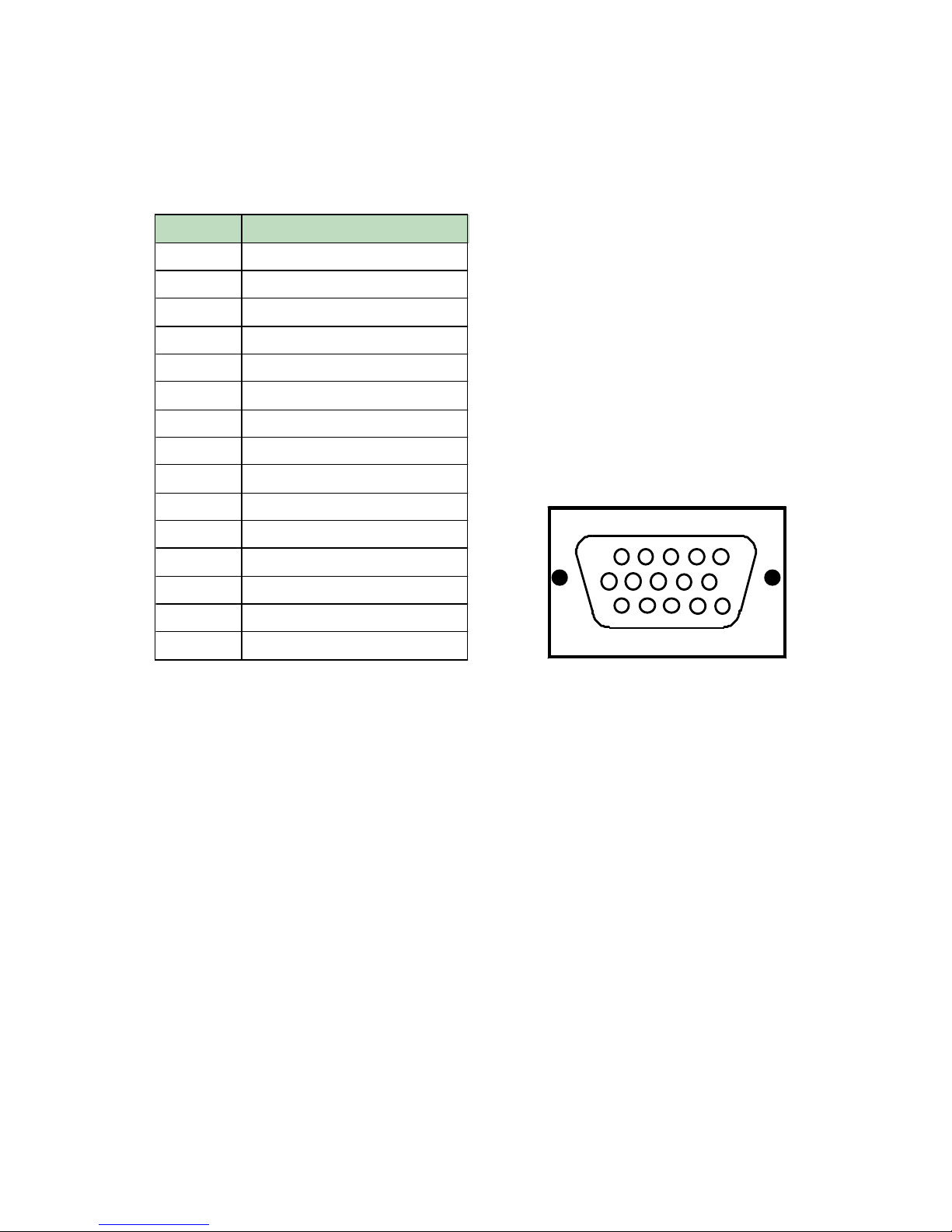
2-2 D-SUB SIGNAL CABLE SPECIFICATION
PIN NO PIN NAME
1 RED
2 GREEN
3 BLUE
4 GND
5 GND (DDC)
6 R-GND
7 G-GND
8 B-GND
9 N.C
10 SELF RASTER
11 GND
12 SDA (DDC)
13 H-SYNC
14 V-SYNC
15 SCL (DDC)
1 2 3 4 5
6 7 8 9 10
11 12 13
14 15
- 8 -
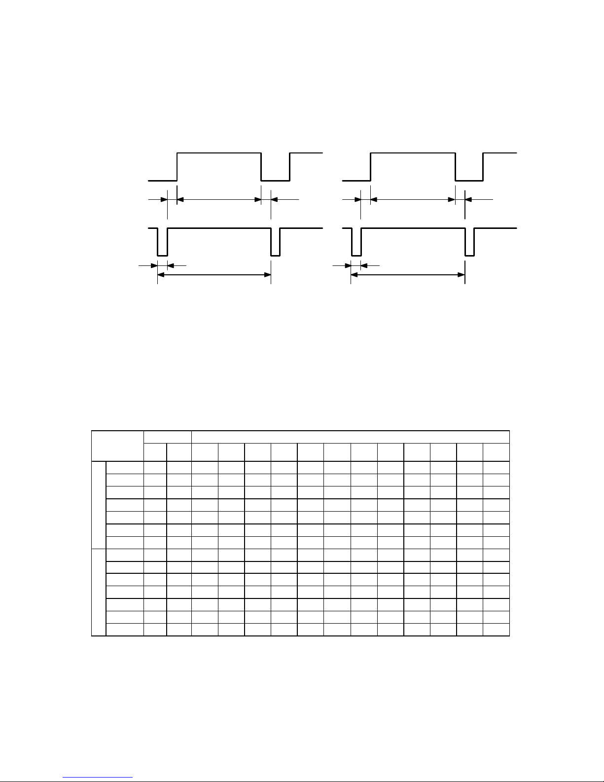
2-3 TIMING CHART
DESCRPTION
I.B.M VESA
720*400 640*480 1024*768
(I)
640*480 800*600 800*600 800*600 1024*768 800*600 1024*768 1280*1024 1024*768 1280*1024 1024*768
H
f KHz
31.469 31.469 35.52 37.860 37.88 46.875 48.077 48.363 53.674 56.476 63.702 68.677 79.976 81.400
A uS
31.778 31.778 28.15 26.413 26.40 21.333 20.800 20.677 18.631 17.707 15.698 14.561 12.504 12.285
B uS
3.813 3.813 3.92 1.270 3.20 1.616 2.400 2.092 1.138 1.813 1.358 1.016 1.067 0.988
C uS
1.907 1.907 1.25 4.603 2.20 3.232 1.280 2.262 2.702 1.920 1.812 2.201 1.837 1.624
D uS
25.422 25.422 22.80 20.317 20.00 16.162 16.000 15.754 14.222 13.653 12.075 10.836 9.481 9.037
E uS
0.636 0.636 0.18 0.762 1.00 0.323 1.120 0.369 0.569 0.320 0.453 0.508 0.119 0.635
POL.
NEG NEG POS POS POS POS POS NEG POS NEG NEG POS NEG POS
V
f Hz
70.087 59.940 86.906 72.809 60.317 75Hz 72.188 60.00 85.061 70.00 60.00 84.997 75.025 100.00
O mS
14.268 16.683 11.50 13.735 16.58 13.333 13.853 16.667 11.756 14.272 16.640 11.765 13.329 10.000
P mS
0.064 0.064 0.113 0.079 0.11 0.064 0.125 0.124 0.056 0.106 0.047 0.044 0.038 0.037
Q mS
1.080 1.048 0.563 0.740 0.61 0.448 0.478 0.60 0.503 0.513 0.471 0.524 0.475 0.516
R mS
12.711 15.253 10.81 12.678 15.84 12.8 12.480 15.88 11.179 13.599 16.075 11.183 12.804 9.435
S mS
0.413 0.318 0.014 0.238 0.03 0.021 0.770 0.062 0.019 0.053 0.047 0.015 0.013 0.012
POL.
POS NEG POS POS POS POS POS NEG POS NEG NEG POS POS POS
VIDEO
SYNC
HORIZONTAL VERTICAL
A
B
C D
E
O
P
Q R
S
A : LINE TIME TOTAL B :HORIZONTAL SYNC WIDTH
C : BACK PORCH D : ACTIVE TIME
E : FRONT PORCH
O : F RAME TIME TOTAL P : VERTICAL SYNC WIDTH
Q : BACK PORCH R : ACTIVE TIME
S : FRONT PORCH
- 9 -
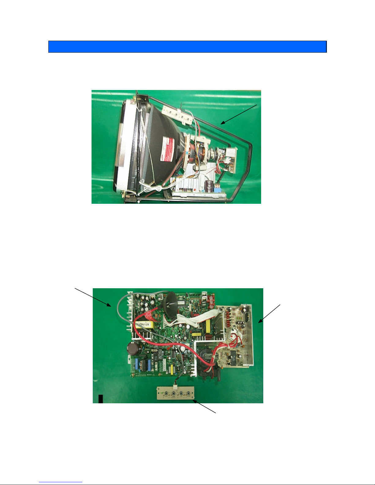
3-1 FRONT FRAME
3.2 MAIN PCB ASS'Y
3. Operating Instruction
KORTEK
STANDARD FRAME
(X-FRAM)
MAIN PCB
SOCKET PCB
CONTROL PCB
- 10 -
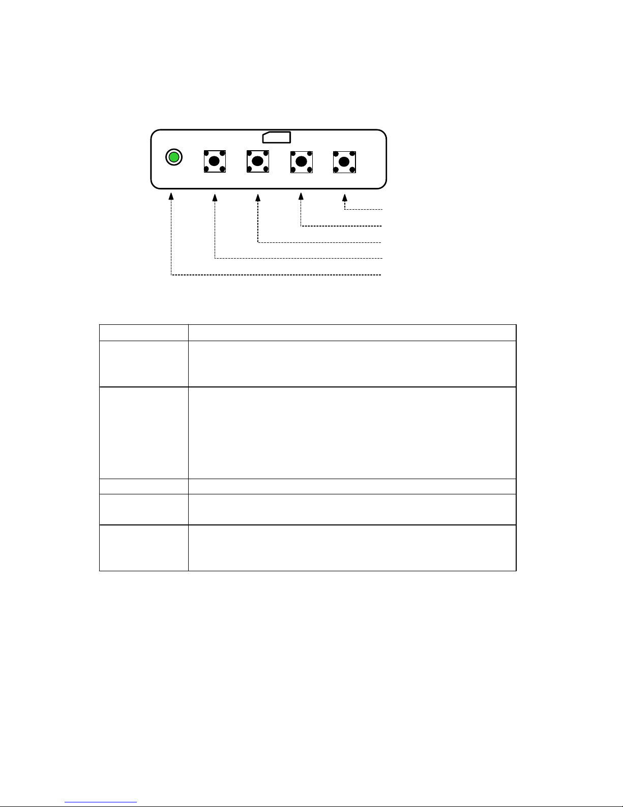
3-3. Function of Control
Control Function
LED
(Power Indicator)
The light of power LED changes according to each state.
◎
on mode : Green LED.
◎
power saving mode : green LED blinking.
MENU(Sellect)
When you press this button, the MENU appears.The MENU will
disappear in 10 seconds if you don't operate any button.
When you press EXIT button again, the MENU disappears.
This button is used to select the control item on the MENU.
In M ENU, the control item could be selected and unselected by
this button.
EXIT This button is used to exit the value of any selected control.
UP
This button is used to increase the value of any selected control.
This button is used to locate to the next control item for select.
DOWN
This button is used to decrease the value of any selected control.
This button is used to locate to the previous control item for
select.
UP
DOWN
MENU (SELECT)
EXIT (DEGAUSSING)
LED

- 11 -
4-1. Adjustment Control
4-1-1. Before making Adjustments
1) Orientation
When servicing, always face the m onitor to east.
2) Warm-up tim e
The monitor m ust be on for 30 minutes before starting alignment. Warm-up
time is especially critical in color temperature and white balance
adjustments.
3) Signal
Analog, 0.714Vp-p positive at 75Ω, internal termination.
4) High Voltage Adjustment
Signal : without signal
Adjustment : 26KV±0.3KV.
PROCEDURE
①
Disconnect the AC line cord from the power source.
②
Connect positive end of High Voltage probe to anode cap of CRT, negative
end of to GND(main chassis)
③
First of all Disconnect AC cord and than disconnect High voltage probe.
5) Screen Voltage
- signal : 1024 x 768 (48KHz) , Full white
- Bright : max
- Contrast : max
- Adjustment (SAM SUNG SDI) : 580±10V
4-1-2 TURN ON THE FACTORY OSD MANUAL METHOD
1) press on the "UP" key.
2) connect the AC line cord from the power source.
3) At this time OSD menu changed factory mode.
4.Adjustments
◑
HV AC VF
BRIGHTNESS
31.4KHz
60Hz
OSD
OSD
i
- 12 -
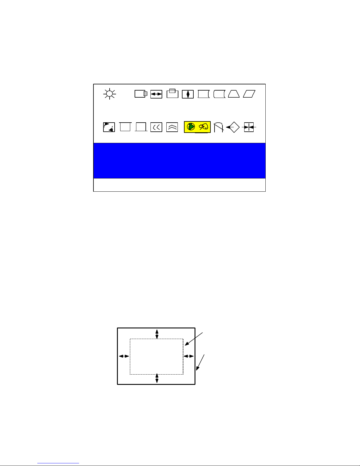
4-2. Display Control Adjustment
Click on the "MENU" button (OSD MENU).
This m enu is user's OSD manual.(user's manual)
1) Click on the "MENU" button.
2) Click on the "UP"or "DOWN" and move any function control.
3) Press the "MENU(SELECT)" button.
4) "UP" or "DOWN" button is used to control the value of any function.
5) When you press exit button, the MENU disappears.
4-2-1 Screen center adjustment
width : 21"(400mm),19"(360mm),17"(320mm)
height : 21"(300mm),19"(270mm),17"(240mm)
signal : 1024 x 768 (48KHz)
|A-B|≤ 4.0mm , |C-D|≤ 4.0mm
a) Horizontal size adjustment
adjustment : use to "H-SIZE"
◑
BRIGHTNESS
31.4KHz 60Hz
DISPLAY AREA
SQUARE CORNER
A
D
C
B

- 13 -
b) Vertical size adjustment
adjustment : use to "V-SIZE"
c) Horizontal position adjustment
adjustment : use to "H-POS"
d) Vertical position adjustment
4-2-2 Trapezoid adjustment
frequency : all mode
signal pattern : cross hatch
4-2-3 Pin balance adjustment
frequency : all mode
signal pattern : cross hatch
4-2-4 Parallelogram adjustment
frequency : all mode
signal pattern : cross hatch
A
B
A
B
|A-B|< 2.5mm
D1 D2 D1
|D1|,|D2|≤1mm
5mm
 Loading...