

KORINS EPIP-40 /30A(I), EPIP-40 /20A(I), EPIP-40 /40A(I) Instruction Manual
1 Characteristic
• PWM or ON/OFF series battery charging
• state of charge (SOC) battery regulation
• battery Ah setting, boost charging, equalizing charging, float charging
• automatic load reconnection, manual load switch
• automatic selection of voltage (12 V / 24 V) • temperature compensation
• lighting control and timer setting options during nighttime(for type –T)
EPIP-40 SERIES SOLAR CHARGE CONTROLLER
• LCD display: SOC as a fuel gauge, all system parameters in digital value, system
status as symbols
─for solar PV system
• full circuit protection, electronic fuse • field adjustable parameters by four buttons
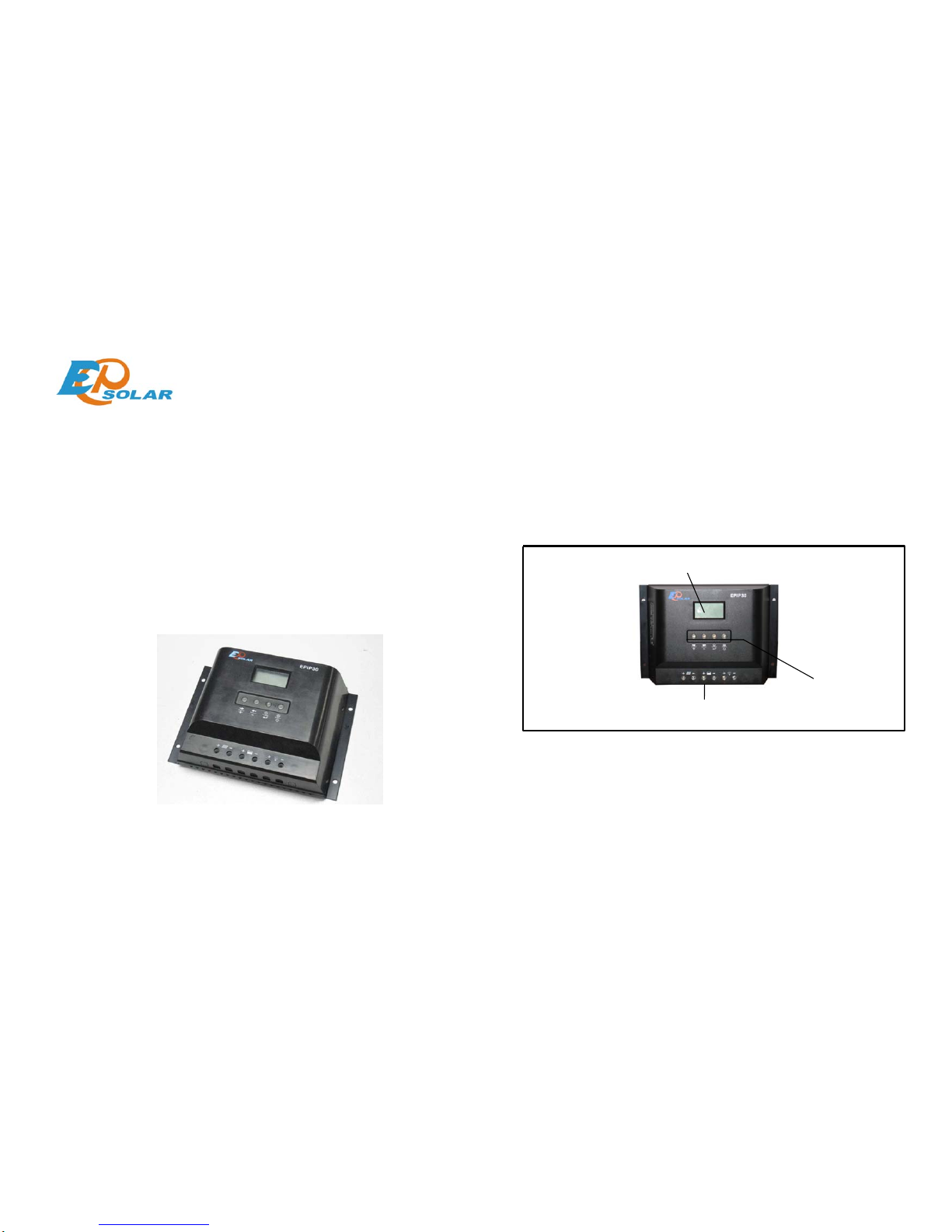
2 Controller panel instructions
INSTRUCTION MANUAL
Customer service:86-10-82894856,82894896
Terminal board
LCD digital and figure display
4 key setting
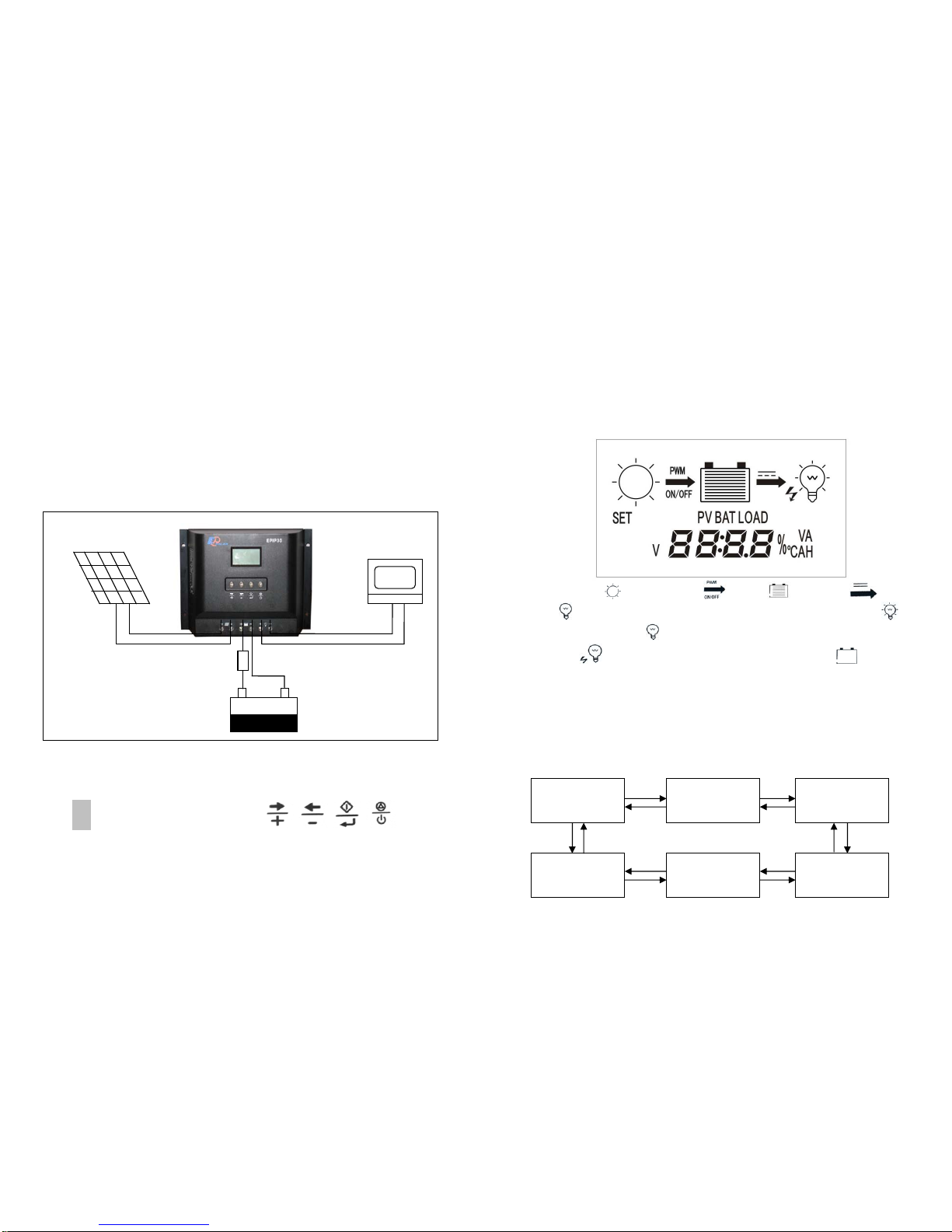
3Installation:
Connect the individual components to the symbols provided, they are solar panel,
battery and loads in order. Only install the regulator near the battery on a suitable
surface. This surface should be solid, stabile, even, dry and nonflammable. The battery
cable should be as short as possible (1-2 m) and have a suitable cable diameter
size to minimize loss, e.g. use 2.5 mm² at 10 A and 2 m length; 4 mm² at
20 A and 2m length; 6 mm² at 30 A and 2 m length.
Observe the following connection sequence during commissioning:
1. Connect the battery to the charge regulator - plus and minus, note the fuse current
should be 2 or 2.5 times of the rated current.
2. Connect the photovoltaic module to the charge regulator
- plus and minus
3. Connect the consumer to the charge regulator - plus and minus
Please observe that the automatic adjustment to 12V / 24V systems
does not function properly, if this sequence order is not followed. An
improper sequence order can damage the battery!
4 Operation & instructions:
4.1 Keys & instructions(from left to right)
¾ K1: reading status, switch to next figure;Setting status, switch to next
function or increase the setting data.
¾ K2:Reading status, switch to the previous figure; setting status, switch
to the previous function or decrease the setting data.
¾ K3: On reading status, press K3, then on setting status; on setting
status, press K3, and save the data, back to reading status.
¾ K4: cancel/power switch, on setting status, no saving with K4. On
reading status, K4 is power switch while loads are working. Recovery
key while it’s short-circuited or over load.
4.2 Display instructions:LCD display as the setting market:
System assembly
Solar module
Battery
fuse
load
LCD displays
、charging mode 、battery 、DC output and
load
,Press K4 while the system is connected, then it shows load ,
while over load, the load flashes,while short circuit protection, load and
lightning flashes,while battery over discharging, the battery flashes,
it stopped while its charged.LCD display “PV”,“BAT”, “LOAD” for solar module,
battery or load separately.“SET” shows on setting status;bottom of LCD display
the specifications & unit “V”,“A”,“AH”,“℃”;
+
-
+ -
+
-
4.3 Operation instructions:
4.3.1 System is on reading status after its assembly. The LCD display: xx.xV;
4.3.2 Reading specifications::On reading status, press K1, K2 and will repeating
the following specifications.
Battery temperature
XX.X ℃
Battery voltage
XX.X V
Battery capacity
XXXX AH
4.3.3 battery capacity modify: while display battery capacity XXXXAH,press k3
Load current Charging current
XX.X A
Voltage of solar module
XX.X V XX.X A
 Loading...