

Page 1

Korenix JetWave 2800 Series
Industrial Outdoor Wireless Access Point
User Manual
V1.0 Apr. 2013
Page 2

Copyright
Copyright © 2013 all rights reserved. No part of this publication may be reproduced, adapted, stored in
a retrieval system, translated into any language, or transmitted in any form or by any means without
the written permission of the supplier.
About This Manual
This user manual is intended to guide professional installer to install the JetWave 2800 and how to
build the infrastructure centered on it. It includes procedures to assist you in avoiding unforeseen
problems.
Conventions
For your attention on important parts, special characters and patterns are used in this manual:
This indicates an important note that you must pay attention to.
This indicates a warning or caution that you have to abide.
Bold: Indicates the function, important words, and so on.
Note:
Warning:
Page 3

Federal Communication Commission Interference Statement
This equipment has been tested and found to comply with the limits for a Class B digital device,
pursuant to Part 15 of the FCC Rules. These limits are designed to provide reasonable protection
against harmful interference in a residential installation. This equipment generates uses and can
radiate radio frequency energy and, if not installed and used in accordance with the instructions, may
cause harmful interference to radio communications. However, there is no guarantee that
interference will not occur in a particular installation. If this equipment does cause harmful
interference to radio or television reception, which can be determined by turning the equipment off and
on, the user is encouraged to try to correct the interference by one of the following measures:
- Reorient or relocate the receiving antenna.
- Increase the separation between the equipment and receiver.
- Connect the equipment into an outlet on a circuit different from that to which the receiver is
connected.
- Consult the dealer or an experienced radio/TV technician for help.
This device complies with Part 15 of the FCC Rules. Operation is subject to the following two
conditions: (1) This device may not cause harmful interference, and (2) this device must accept any
interference received, including interference that may cause undesired operation.
FCC Caution: Any changes or modifications not expressly approved by the party responsible for
compliance could void the user's authority to operate this equipment.
Page 4

FCC Radiation Exposure Statement:
This equipment complies with FCC radiation exposure limits set forth for an unco ntrolled environment.
To avoid the possibility of exceeding radio frequency exposure limits, you shall beep a distance of at
least 100cm between you and the antenna of the installed equipment. This transmitter must not be
co-located or operating in conjunction with any other antenna or transmitter.
The availability of some specific channels and/or operational frequency bands are country
dependent and are firmware programmed at the factory to match the intended destination. The
firmware setting is not accessible by the end user.
Page 5

Content
Chapter 1 Introduction ......................................................................................................................... 1
Introduction ......................................................................................................................................... 1
Appearance ........................................................................................................................................ 2
Key Features ...................................................................................................................................... 2
Typical Application ........................................................................................................... ................... 3
Chapter 2 Hardware Installation ......................................................................................................... 4
Preparation before Installation ............................................................................................................ 4
Professional Installation Required .................................................................................................. 4
Safety Precautions .......................................................................................................................... 4
Installation Precautions ................................................................................................................... 5
Product Package ............................................................................................................................. 5
Hardware Installation .......................................................................................................................... 7
Connect up ...................................................................................................................................... 7
Pole Mounting ............................................................................................................................... 10
Using the External Antenna .......................................................................................................... 12
Chapter 3 Web Settings ..................................................................................................................... 14
Factory Default Settings ................................................................................................................... 14
System Requirements ...................................................................................................................... 15
How to Login the Web-based Interface ............................................................................................ 15
System Setup ................................................................................................................................... 17
Wireless Settings .............................................................................................................................. 21
Administration ................................................................................................................................... 34
Utility ................................................................................................................................................. 38
Status ................................................................................................................................................ 42
Logout(admin) .................................................................................................................................. 45
Chapter 4 Utility .................................................................................................................................. 46
JetWave Viewer Utility ...................................................................................................................... 46
Chapter 5 Troubleshooting ............................................................................................................... 49
Appendix A. ASCII .............................................................................................................................. 51
Revision History ................................................................................................................................. 52
Page 6

Chapter 1 Introduction Page 1
Chapter 1 Introduction
Introduction
The JetWave 2800 is an industrial IEEE 802.11a/b/g/n Wireless AP which offers a high performance
and reliability wireless solution for both 2.4GHz and 5GHz RF bands. With the JetWave 2800 wireless
access point, a network designer will easily achieve the integration of wired and wireless networks.
With the next generation 802.11n MIMO technology, the AP (up to 3 independent RF modules) offer
high data link rate up to 350Mbps in each single radio options, and provide the redundant wireless
connections to increase the reliability of the entire wireless network. The JetWave 2800 can function
as an access, client, or bridge device.
The advanced features include Korenix patented super roaming technology which seamlessly
enabling the applications of high-speed mobility, RSTP, VLAN, and QoS (WMM). For the wireless
security communication, 64/128/152-bit WEP, WPA/WPA2/802.11i, enable/disable SSID broadcasts,
MAC access control, IEEE 802.11X/RADIUS are supported. The JetWave 2800 provides an industrial
level of immunity to electromagnetic interference and heavy electrical surges. The JetWave 2800
provides PoE compliant power inputs and it can be powered via PoE switch/injector through Ethernet
cable. The IP67 waterproof enclosure (JetWave 2800) with wide -35~70°C ope rating temperature
design allows users to install the device under harsh environmental conditions.
Page 7
Chapter 1 Introduction Page 2
Appearance
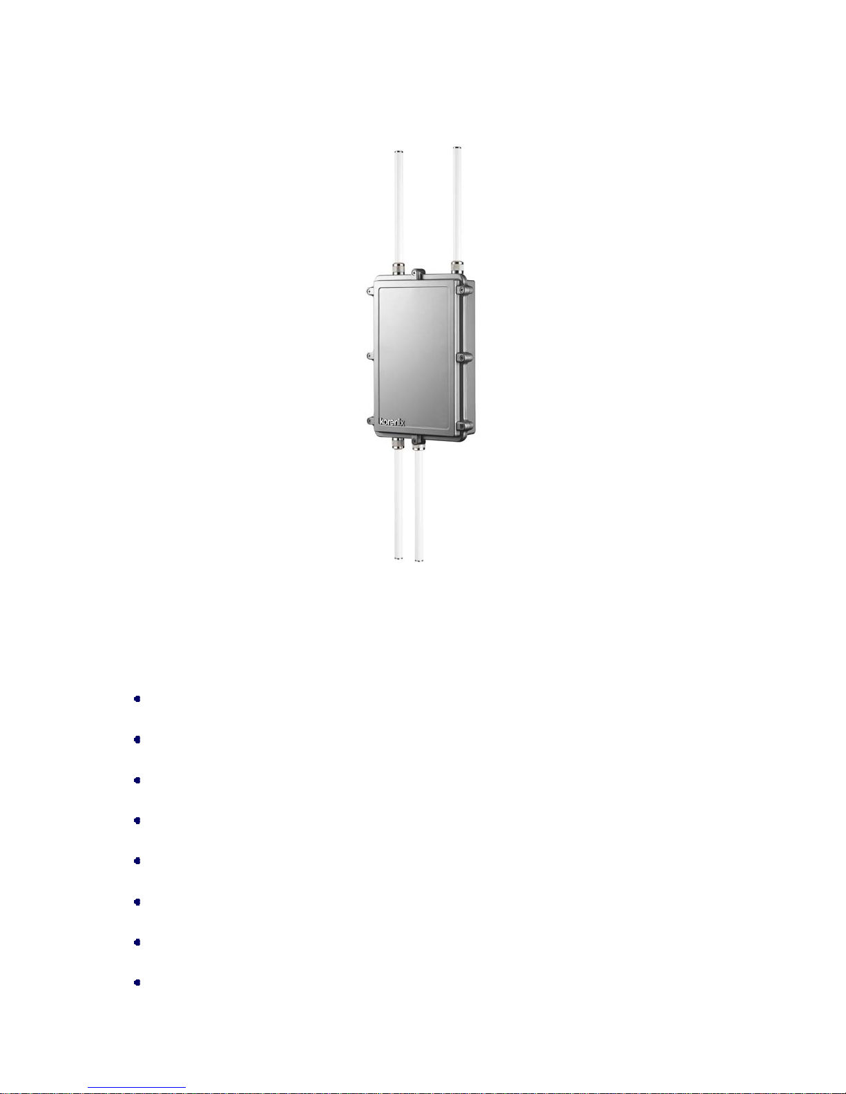
Figure 1 JetWave 2800
Key Features
Single/Dual/Triple RF Configurable: 802.11a/b/g/n and 2.4G/5G
Superb performance: 3RF with 1GbE up to 350Mbps
Strong TX output power extends distance and coverage
High RX sensitivity enhances receiving signal quality
2x2 MIMO doubles data rate
Supports Super Roaming, Mesh, and Mobility mode (2800-M)
Supports high performance multiple hopping mode (2800-H)
Wireless QoS (WMM) for video precedence transmission
Page 8
Chapter 1 Introduction Page 3
High gain weatherproof fiberglass antenna by selection
Gigabit PoE power input, PoE injector included
IP67 aluminum housing, -35~70°C outdoor solution
T ypical Application
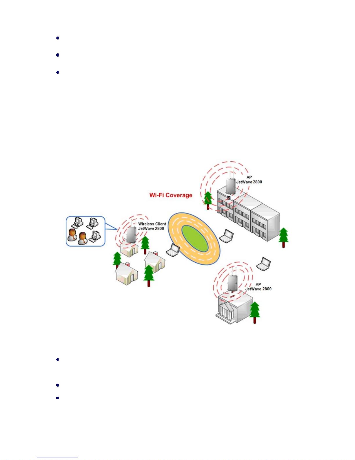
This section describes the typical applications of JetWave 2800. By default, it is set to AP mode which
allows it to establish a wireless coverage; besides, it is also able to join any available wireless network
under wireless client mode. The JetWave 2800 is able to deliver stable and efficient broadband
connectivity for various applications.
Figure 2 Typical Application
Besides, the JetWave 2800 can also be applied into the following environments:
Cost-effectively provide long distance backhaul for remote areas (e.g. village, oil well, island,
mountain and etc.)
Establish local backhaul for campus, farm and factory
Provide and access for video streaming or surveillance for industrial and mining enterp rises
Page 9

Chapter 2 Hardware Installation Page 4
Chapter 2 Hardware Installation
This chapter describes safety precautions and product information you have to know an d check before
installing JetWave 2800.
Preparation before Installation
Professional Installation Required
1. Please seek assistance from a professional installer who is well trained in the RF installation and
knowledgeable in the local regulations.
2. The JetWave 2800 is distributed through distributors and system installers with professional
technicians and will not be sold directly through retail stores.
Safety Precautions
1. To keep you safe and install the hardware properly, please read and follow these safety
precautions.
2. If you are installing JetWave 2800 for the first time, for your safety as well as others’, please
seek assistance from a professional installer who has received safety training on the hazards
involved.
3. Keep safety as well as performance in mind when selecting your installation site, especially
where there are electric power and phone lines.
4. When installing JetWave 2800, please note the following things:
♦ Do not use a metal ladder;
♦ Do not work on a wet or windy day;
♦ Wear shoes with rubber soles and heels, rubber gloves, long sleeved shirt or jacket.
5. When the system is operational, avoid standing directly in front of it. Strong RF fields are present
when the transmitter is on.
Page 10

Chapter 2 Hardware Installation Page 5
Installation Precautions
To keep the JetWave 2800 well while you are installing it, please read and follow these installation
precautions.
1. Users MUST use a proper and well-installed surge arrestor and grounding kit with JetW ave 28 00;
otherwise, a random lightening could easily cause fatal damage to JetWave 2800. EMD
(Lightning) DAMAGE IS NOT COVERED UNDER WARRNTY.
2. Users MUST use the safety certificated PoE switch/injector with the JetWave 2800. The
Industrial PoE Switch is recommended.
3. Users MUST power off the JetWave 2800 first before connecting the external antenna to it;
otherwise, damage might be caused to the JetWave 2800 itself.
Product Package
The product package you have received should contain the following items. If any of them are not
included or damaged, please contact your local vendor for support.
JetWave 2800 ×1
Pole Mounting Kit ×1
Waterproof Cap for RJ-45 ×1
Quick Installation Guide ×1
Product CD ×1
Product CD contains Quick Installation Guide and User Manual!
Note:
Page 11
Chapter 2 Hardware Installation Page 6
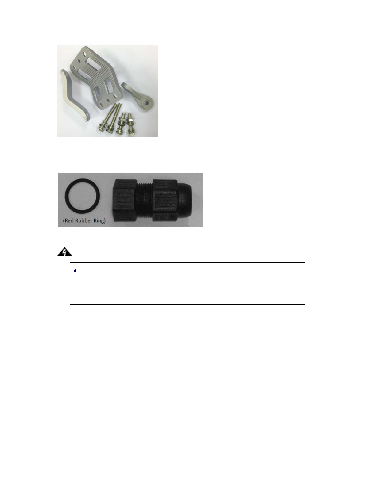
Pole Mounting kit
Waterproof Cap for RJ-45
Users MUST use the safety certificated PoE Switch/Injector with the JetWave 2800.
Use of other non-safety certificated PoE Switch/Injector is easier to cause damage in
the field environment.
Warning:
Page 12
Chapter 2 Hardware Installation Page 7
Hardware Installation
Connect up
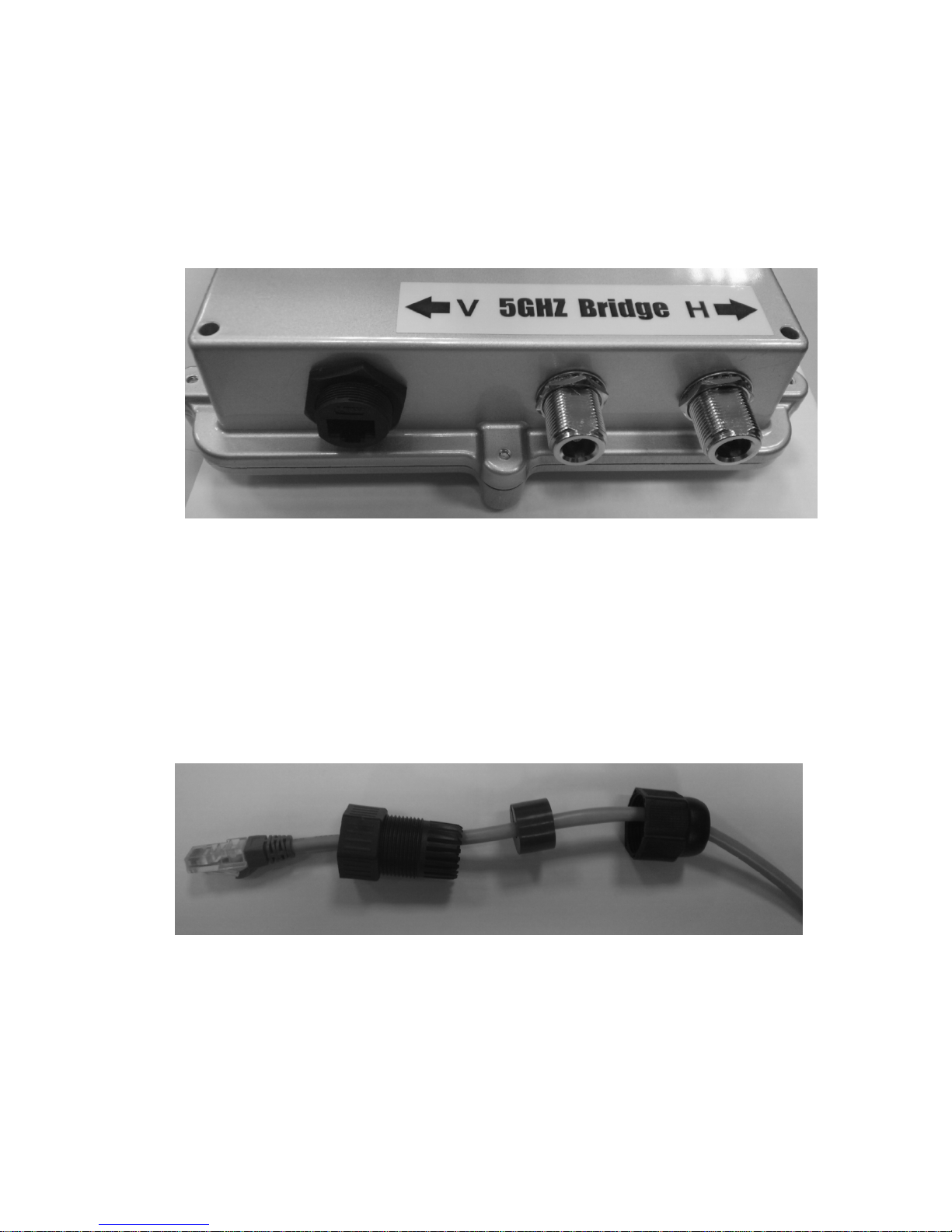
1. Connect the Ethernet cable to the Ethernet Port in the bottom of the JetWave 2800. The
Ethernet port is an IEEE 802.3at compliant PoE port.
Figure 3 The Ethernet port in the bottom of the AP.
2. To have better waterproof protection outside, please follow the below step to install the
Waterproof Cap for RJ-45.
Step 1: Insert the Ethernet Cable to the Waterproof Cap for RJ-45. You may re-assemble the
RJ-45 connector to insert the cap, make sure the cable distance from the PoE switch to the AP.
Check the cable connection is correct before installed it in the field.
Figure 4 Assemble the Ethernet Cable
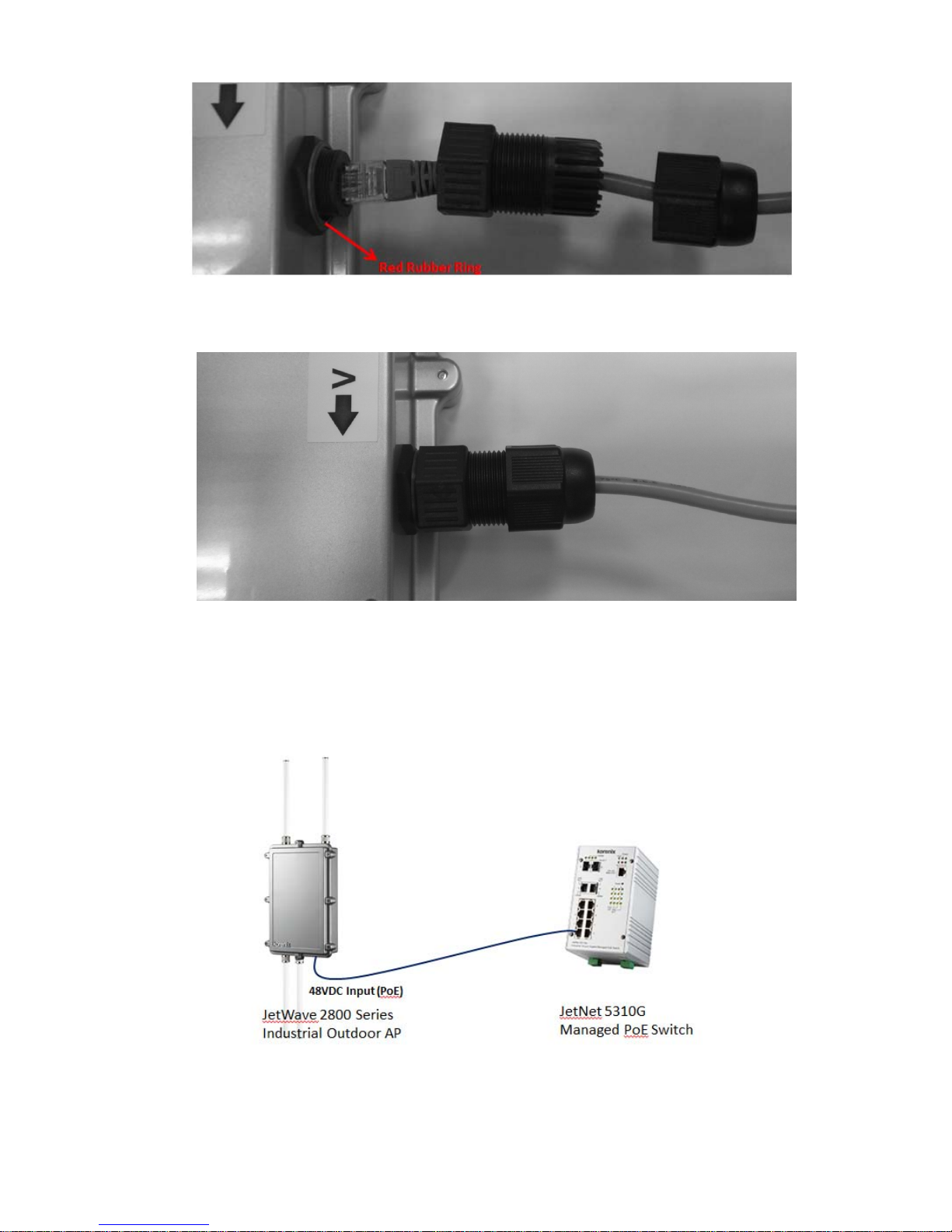
Step 2: Put the red rubber ring to the RJ-45 connector first. Plug the Ethernet Cable into the
RJ-45 port. Note that the CAT 5E/6 cable is recommended.
Page 13
Chapter 2 Hardware Installation Page 8
Figure 5 Connect to the RJ-45 connector
Step 3: Lock the Waterproof Cap for the RJ-45 port.
Figure 6 The Ethernet Cable is well installed.
3. Connect another end of the Ethernet cable to the PoE Switch or PoE Injector. Then the AP can
be powered and user can access its management interface through the cable. Below figure is an
example of Connect AP to the PoE Switch.
Figure 7 Example of Connect AP to the PoE Switch
Page 14

Chapter 2 Hardware Installation Page 9
The AP does not provide PoE injector inside the box.
Please choose Korenix Industrial IEEE 802.3at compliant PoE Switch as power input
source. Thus Korenix can provide better quality assurance for your network.
Note:
Page 15
Chapter 2 Hardware Installation Page 10
Pole Mounting
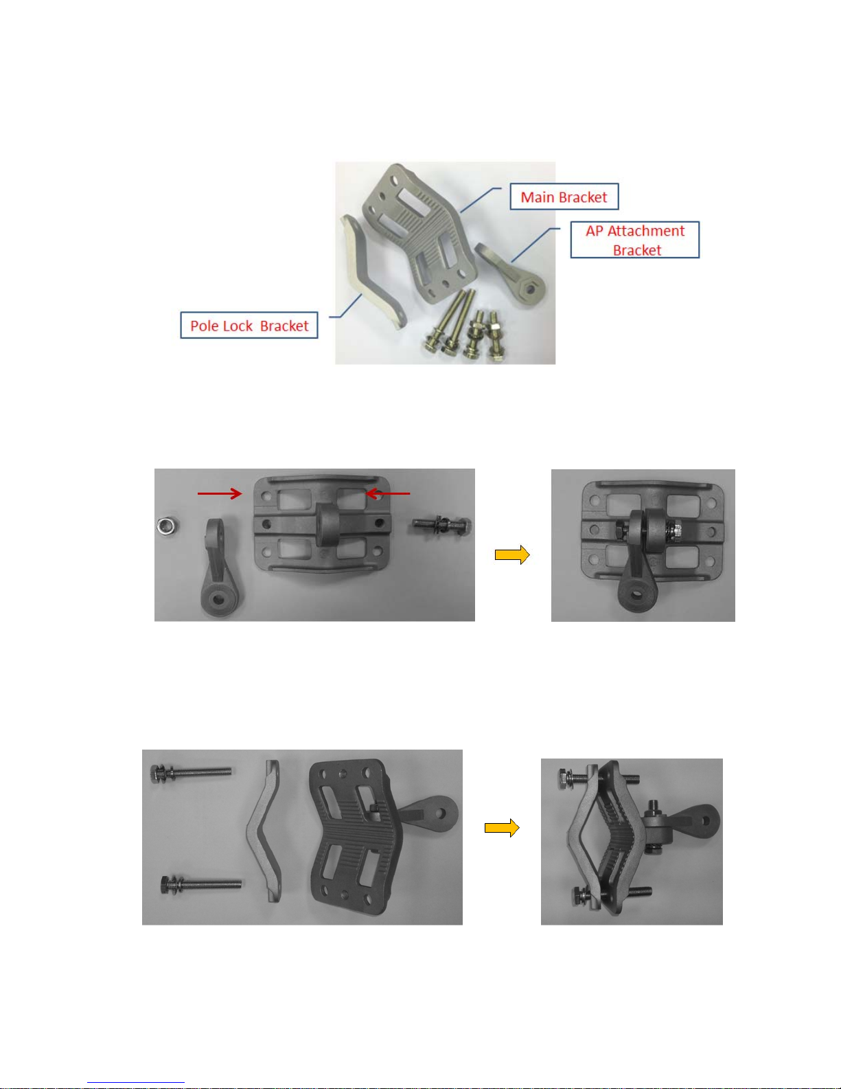
1. The unassembled bracket consists as below. If there is any lost, please contact your sales.
Figure 8 Pole Mounting Kit
2. Following steps show how to assemble the pole mounting kits.
Step 1: Assemble the Main Bracket and AP Attachment Bracket.
Figure 9 Pole Mounting – Main Bracket with AP Attachment Bracket
Step 2: Assemble the Main Bracket and Pole Lock Bracket. (Note: The step is usually
assembled in the field after confirmed the installation place.)
Figure 10 Pole Mounting – Main Bracket and Pole Lock Bracket
Page 16
Chapter 2 Hardware Installation Page 11
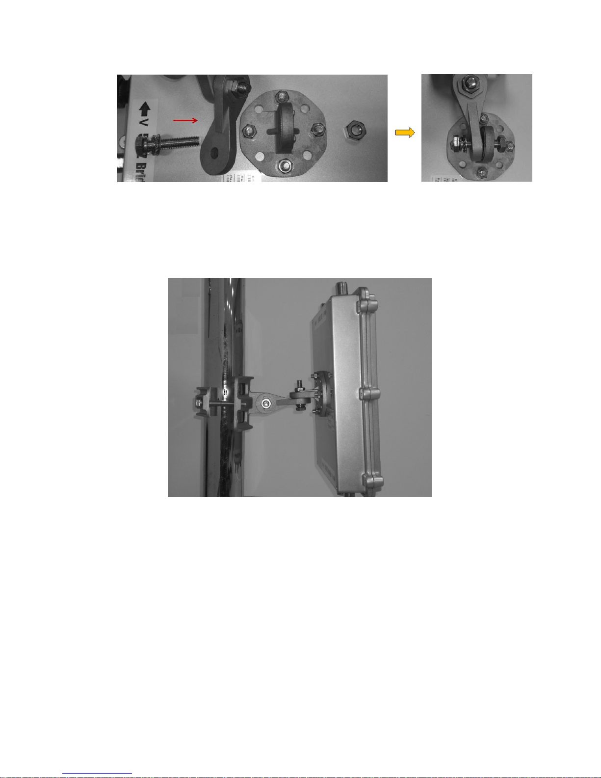
3. Mount the AP to the AP Attachment Bracket.
Figure 11 Mount the AP with AP Attachment Bracket
4. Pole mounting the AP in the field. Below figure shows you have completed the hardware
installation of JetWave 2800.
Figure 12 Pole Mounting the Access Point
Page 17
Chapter 2 Hardware Installation Page 12
Using the External Antenna
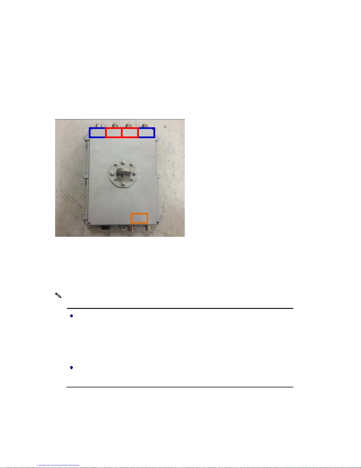
Consult your system integrator or our technical support engineer to choose the suitable external
antenna with N-type connector for your application. Different antenna supports different bands and
different range of coverage. There are indication labels shows which radio t he antenna socket belon gs
to. JetWave 2800 supports maximum 3 Radio cards, please connect your antenna correctly and
configure the band and settings for each of them
Blue block: The antenna of the Radio 1;
Orange block: The antenna of the Radio 2
Red block: The antenna of the Radio 3.
When prepare the external antenna, make sure the antenna can support Dual
Polarization. Most of the high gain antenna supports Dual Polarization. Connect the V
polarization of antenna to V polarization of the AP. The H polarization of antenna to H
polarization of the AP.
Some of the low gain or Omni antenna may not support Dual Polarization, you can
connect 2 the same dbi gain antennas to V and H polarization.
Note:
Page 18
Chapter 2 Hardware Installation Page 13
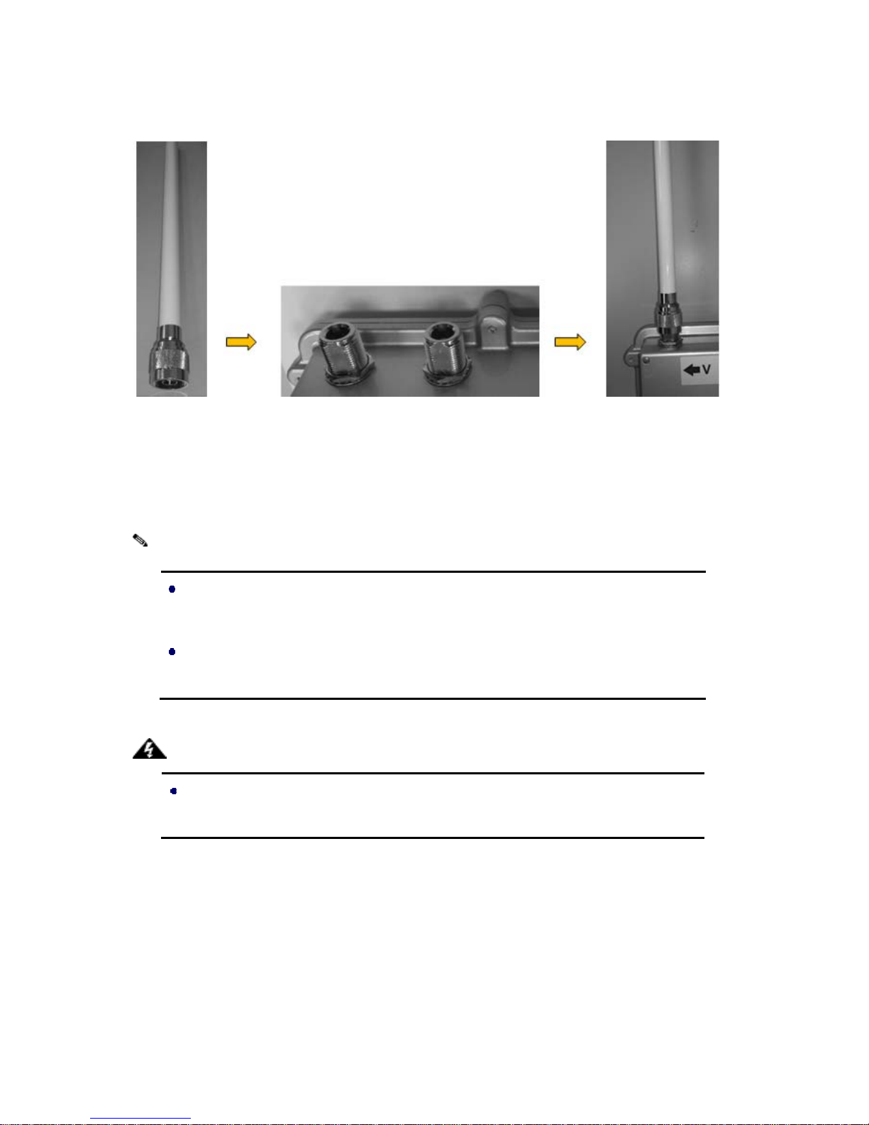
The below figures show the steps to connect the antenna to the antenna sockets.
Connect your antenna with the N-type connector here.
Figure 13 Example of the Connect external Antenna socket: Connect the Omni-Directional
Antenna to the Antenna Socket.
Most of high gain external antenna is installed in higher place than AP, get low power
lost antenna cable in advance.
Be aware of the force you use while connecting to the N-type connector, inappropriate
force may damage the N-type connector!
Users MUST power the JetWave 2800 off first before connecting the external antenna
to it; otherwise, damage might be caused to the JetWave 2800 itself.
Warning:
Note:
Page 19

Chapter 3 Basic Settings Page 14
Chapter 3 Web Settings
The Web Setting is applied to JetW ave 2700/2800 Series.
The MESH and Roaming features are applied to specific models. The JetWave 2700/2800-M means
MESH mode, it supports wireless Mesh network and Fast Roaming feature.
Factory Default Settings
We’ll elaborate the JetWave 2800 factory default settings. You can re-acquire these parameters by
default. If necessary, please refer to the “Administration”.
T able 1 JetWave 2800 Factory Default Settings
Features Factory Default Settings
Username admin
Password admin
Language English
Device Name FSA
System Operation Mode Bridge
IP Setup
IP Address 192.168.1.1
Subnet Mask 255.255.255.0
Gateway 0.0.0.0
Primary DNS Server 0.0.0.0
Secondary DNS Server 0.0.0.0
Spanning Tree Protocol Off
Ethernet Link Speed Auto
DHCP Server Off
Management VLAN 0 (Disable)
Radio Setup
Radio - 1/2
Wireless Band 802.11ng HT20
Channel
Radio 1: 1 CH - 2412MHz
Radio 2: 6 CH - 2473MHz
Transmission Power Full
Antenna Number 2
Short Guard Interval On(400ms)
Aggregation Enable
Distance (x100m) 0
WLAN Setup
Radio-1/2
SSID
Radio 1: wireless_1
Radio 2: wireless_2
(Broadcast Enable)
Enable Yes
WLAN Mode Access Point
Page 20

Chapter 3 Basic Settings Page 15
RTS 2312
Fragmentation 2346
Limited Data Rate Auto
Multicast Rate Auto
Rate Adaption Default
VLAN ID: 0, Priority: 0
Client Numbers 64
Client Isolation Off
Bandwidth Profile 0-Disable
Wireless Security
SSID wireless_1
MAC Filter Disable
Security Disable
MESH Setup Disable
WMM Setup
Radio Radio 1
Enable NO
Bandwidth Control
Profile Setup
Profile ID 1
Mode Disable
SNMP Disable
System Log
Syslog Level Informational
Remote logging Diable
Remote IP 0.0.0.0
Certificate management Empty
System Requirements
Before configuration, please make sure your system meets the following requirements:
A computer coupled with 1 0/100/1000 Base-T(X) adapter;
Configure the computer with a static IP address of 192.168.1.x, as the default IP address of
JetWave 2800 is 192.168.1.1 (X cannot be 0, 1, nor 255);
A Web browser on PC for configuration such as Microsoft Internet Explorer 6.0 or above,
Netscape or Firefox.
How to Login the Web-based Interface
The JetWave 2800 provides you with user-friendly Web-based management tool.
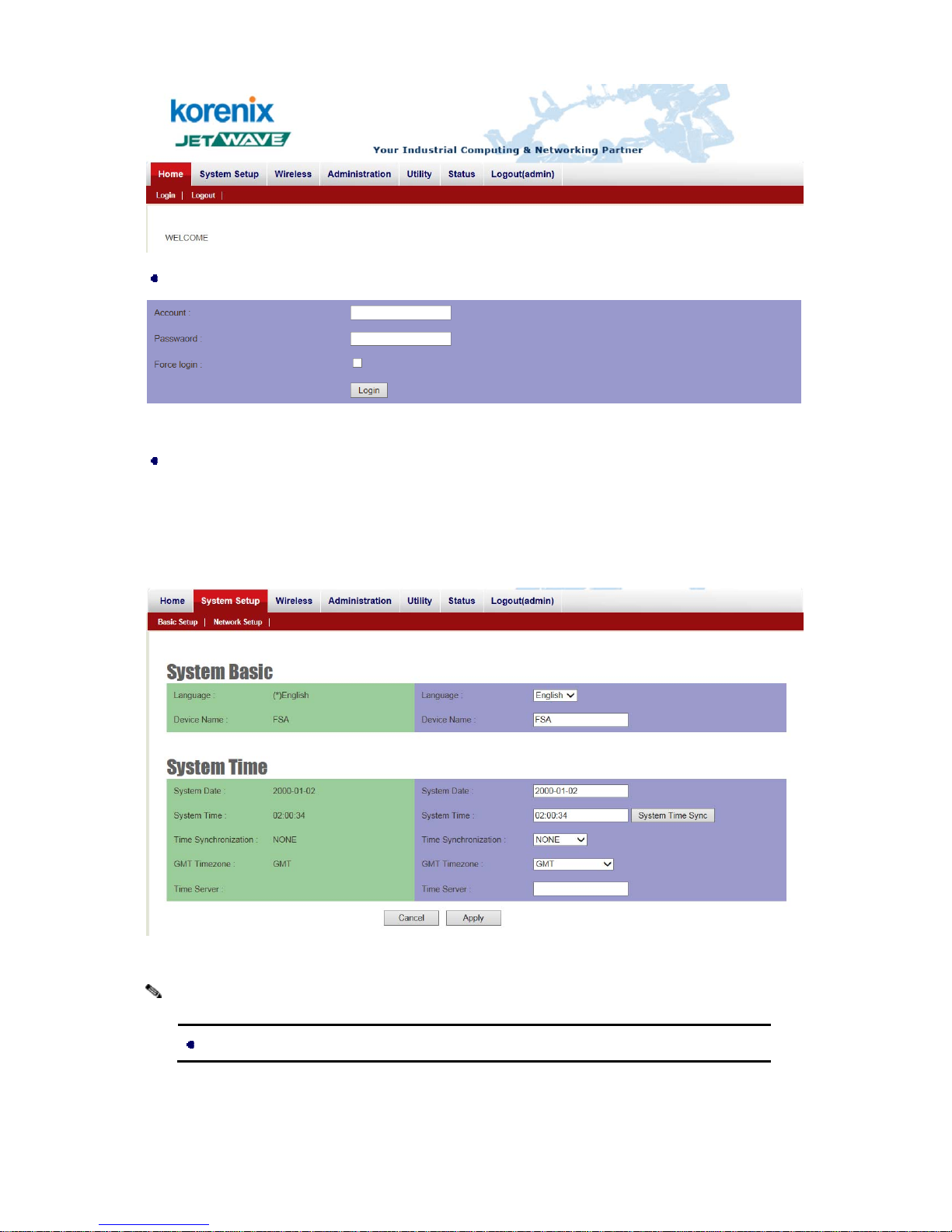
Open IE and enter the IP address (Default: 192.168.1.1) of JetWave 2800 into the address field.
You will see the WELCOME page as below.
Page 21
Chapter 3 Basic Settings Page 16
Select the Login, then the login screen will appear as below.
Figure 4 Login Page
Enter the name of Account (Default: admin) and password (Default: admin) respectively and click
“Login” to login the main page of JetWave 2800. As you can see, this management interface
provides main options in the above, which are Home, System Setup, Wireless, Administrator,
Utility, Status and Logout(admin).
Figure 5 Main Page
The username and password are case-sensitive!
Note:
Page 22
Chapter 5 Management Page 17
System Setup
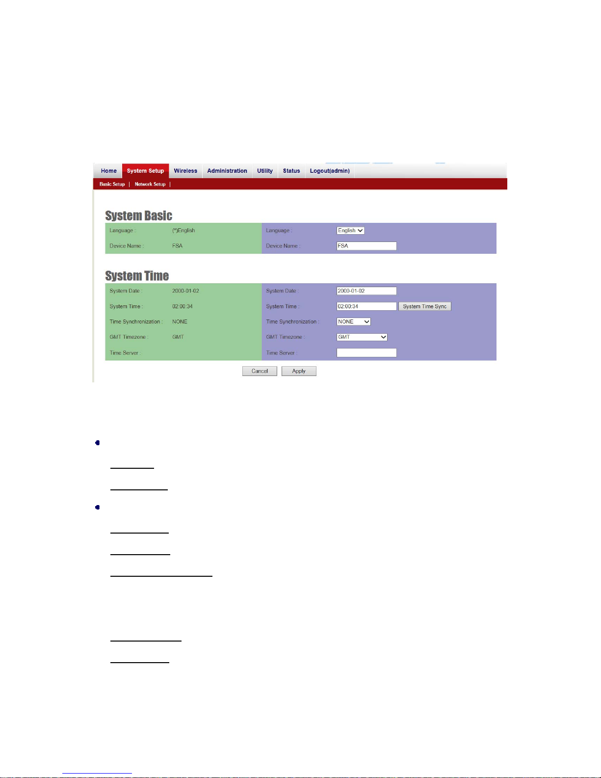
For users who use the JetWave 2800 for the first time, it is recommended that you begin configuration
from “System Setup” shown below:
In System Setup page, there are 2 configuration pages, Ba sic Setup and Network Setup.
Figure 6 Basic System Settings
Basic Setup:
System Basic
Language: The AP support English language currently.
Device Name: User could give a name for identifying a particular outdoo r access point in here.
System Time
System Date: User would like to set the date manually in this item.
System Time: User would like to set the time manually in this item.
Time Synchronization: Time synchronization setting will decide the duration to next time
synchronization. When any NTP server is available in network, user can enable the NTP and
system will automatically synchronize system time with NTP server.
GMT Time zone: Set a Greenwich Mean Time setup for time synchronization.
Time Server: User can insert an available IP address of NTP server in Internet for time
synchronization.
Page 23

Chapter 5 Management Page 18
Network Setup:
Figure 77 Network Setup
System Operation Mode: Bridge or Router (The default value is Bridge mode)
Bridge: When configured to Bridge mode, the AP acts as bridge to transmit/receive traffic
between LAN to Wireless LAN. And there is only one IP address available for the system.
Router: When configured to Router mode, the AP acts as Router, the LAN and Wireless LAN will
be separated to different network. See Router Mode – WAN/LAN Setup for detail configuration.
Bridge Mode - IP Setup
IP Address: Once Stat ic IP was selected, the IP Address field will allow you to set the bridge
device IP address manually. This IP address of the bridge is used as the base for all of your local
Page 24
Chapter 5 Management Page 19
network settings.
Subnet Mask: This is the subnet mask address for your bridge device. Set the IP subnet mask
manually.
Default Gateway: Set the default gateway IP address manually.
DNS 1 & 2: The Domain Name System (DNS) is how the Internet translates domain or website
names into Internet addresses or URLs. Your ISP will provide you with at least one DNS Server IP
Address. If you wish to use another, enter that IP Address in DNS 2 field.
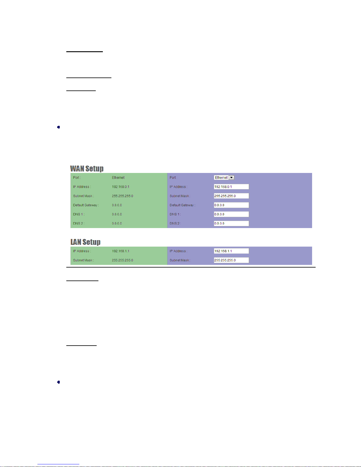
Router Mode - W AN/LAN Setup
When configured the System Operation Mode to Router mode, the Web interface show s below 2
new configuration fields.
WAN Setup: The page allows you to configure the IP Address, Subnet Mask, Default Gateway
and DNS 1/2 for the WAN Port. While the WAN Port is Ethernet port, the settings will be applied
to the Ethernet RJ-45 port.
Note: If your PC is not located within the same IP subnet of the WAN port, please remember to
modify your PC’s IP address to re-connect the AP.
LAN Setup: The page allows you to change the IP address, Subnet Mask for the LAN.
Click Apply after configured the new settings. The new settings are activated immediately after
you applied.
Spanning Tree Protocol
The Spanning Tree Protocol (STP) is a network protocol that ensures a loop-free topology for any
bridged Ethernet local area network. The basic function of STP is to prevent bridge loops and
ensuing broadcast radiation. Spanning tree also allows a network design to include spare
Page 25
Chapter 5 Management Page 20
(redundant) links to provide automatic backup paths if an active link fails, without the danger of
bridge loops, or the need for manual enabling/disabling of these backup links.
This setting allows you to configure STP ON, OFF or Rapid STP mode.
Ethernet Link Speed
Link The link speed of Ethernet port can be changed manually into 10/100 Half/Full duplex.
DHCP Server Setting
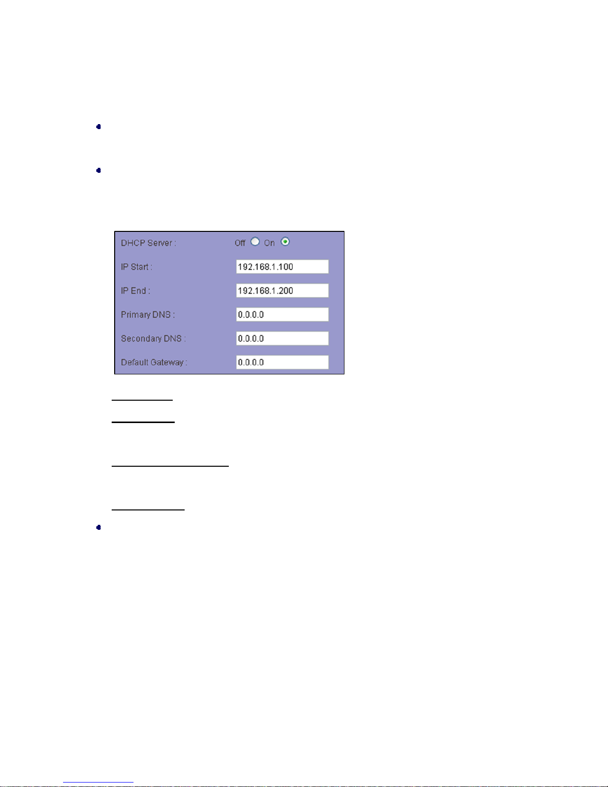
The AP can be configured as a DHCP server for a LAN network. Once the DHCP Server is chose
as on, the DHCP server setting elements will spread out on the page.
DHCP Server: Allows you to enable or disable the DHCP server function in system.
IP Start / End: The IP Start and End Address specify the range of addresses assigned by your
device when it functions as a DHCP server.
Primary & Secondary DNS Set the primary and secondary DNS server IP address which DHCP
server is going to assign for DHCP client devices.
Default Gateway Default gateways IP address assign for DHCP client devices.
Management VLAN
Management VLAN is a secure VLAN which divides Internet users from device IP access.
Administrators can management network devices under the Management LAN network without
betrayal of secrets.
Page 26
Chapter 5 Management Page 21
Wireless Settings
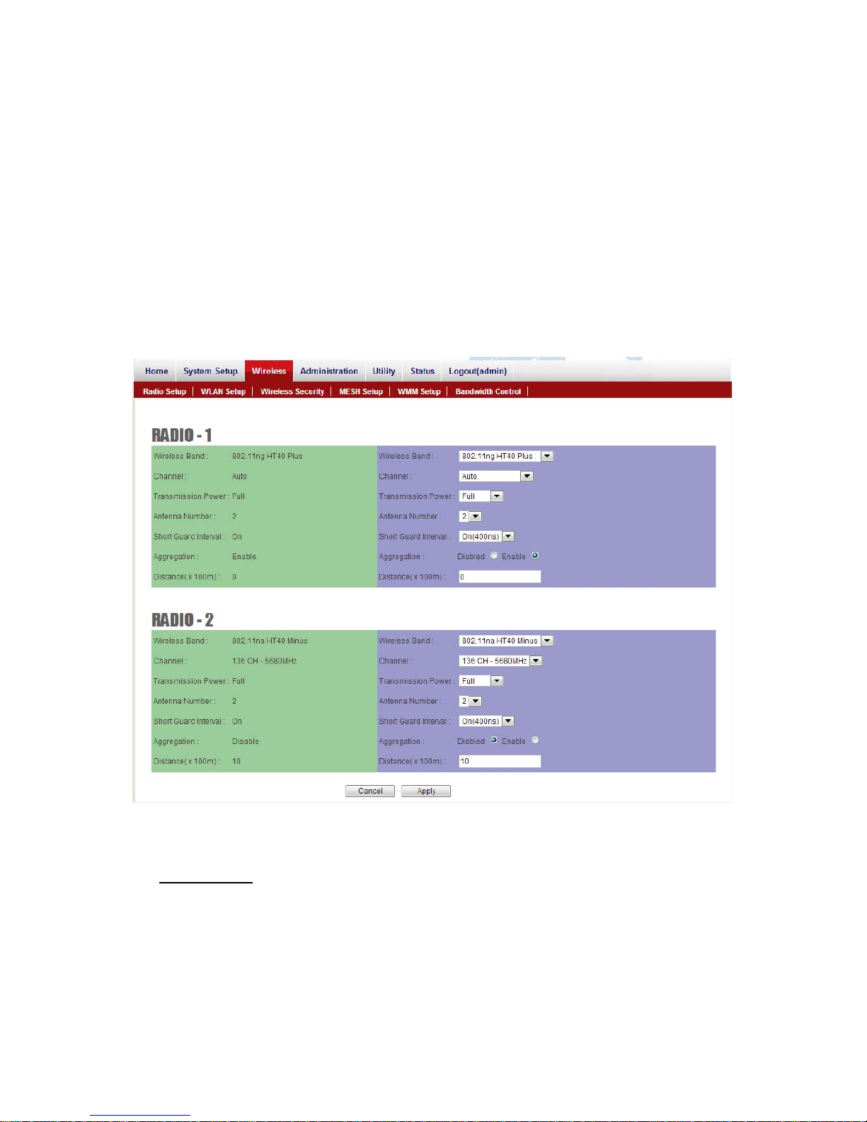
Open “Wireless” as below to make basic wireless configuration.
There are several settings such as the Radio Setup, WLAN Setup, Wireless Security, MESH Setup,
WMM Setup and Bandwidth Control can be configured in the Wireless Configuration.
Radio Setup
Figure 8 Wireless Settings
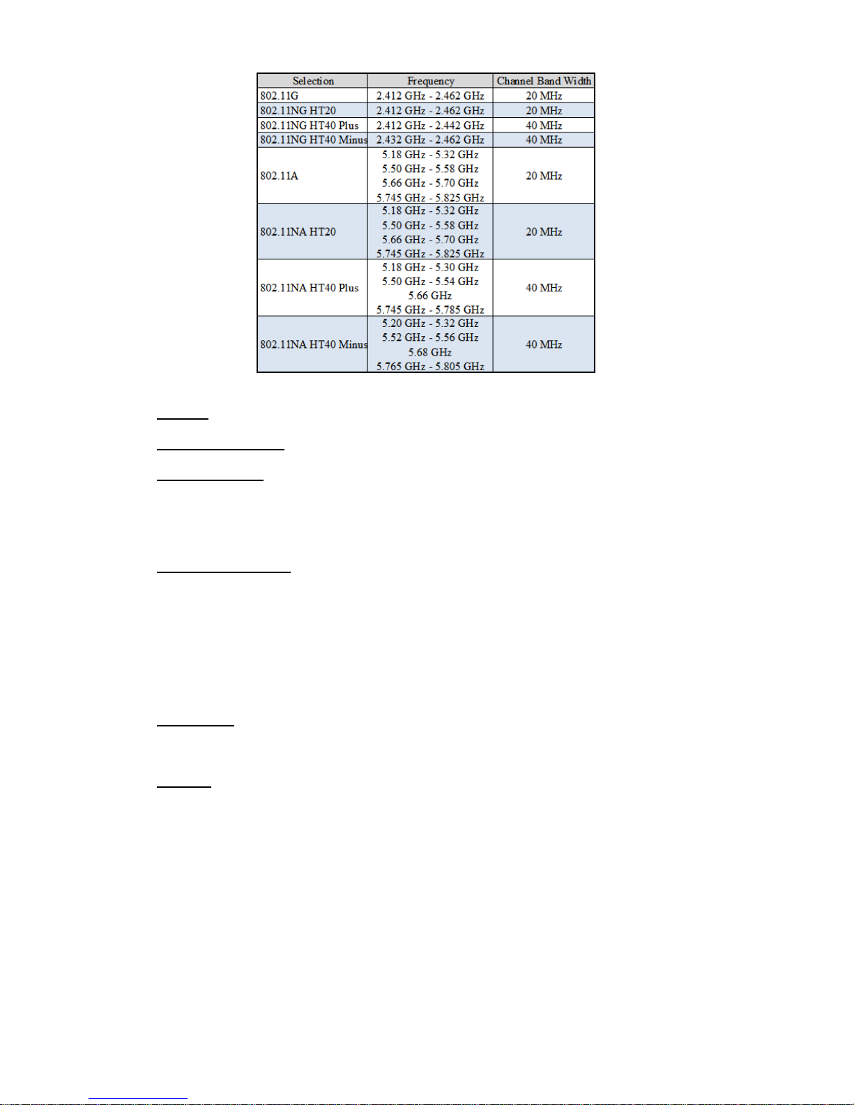
Wireless Band Choose a radio frequency for signal transmission. The frequency and channel
bandwidth match to selection is showed as following table:
Page 27
Chapter 5 Management Page 22
Channel Available channel will relate to what wireless band is cho s en.
Transmission Power Control the transmit powe r of a radio by selection of Transmission Power.
Antenna Number The JetWave 2800 series complete 802.11n 1x1 1-steram and 2x2 2-stream
for antenna attached. The maximum data link rate at 1-steram and 2-stream will be 130Mbps and
300Mbps.
Short Guard Interval The guard interval is the space between symbols (characters) being
transmitted. Adding time between symbol transmissions allows these echoes and reflections to
settle in before the next symbol is transmitted. In normal 802.11 operations, the guard interval is
800ns. A short guard interval will short the time between symbol transmissions into 400 ns to
enhance the efficiency of data transmission.
Aggregation Frame aggregation is a feature of the 802.11n wireless LAN standards that
increases throughput by sending two or more data frames in a single transmission.
Distance To assign a distance between nodes in a point to point transmission will improve the
success rate of data transmit.
WLAN Setup
Page 28
Chapter 5 Management Page 23
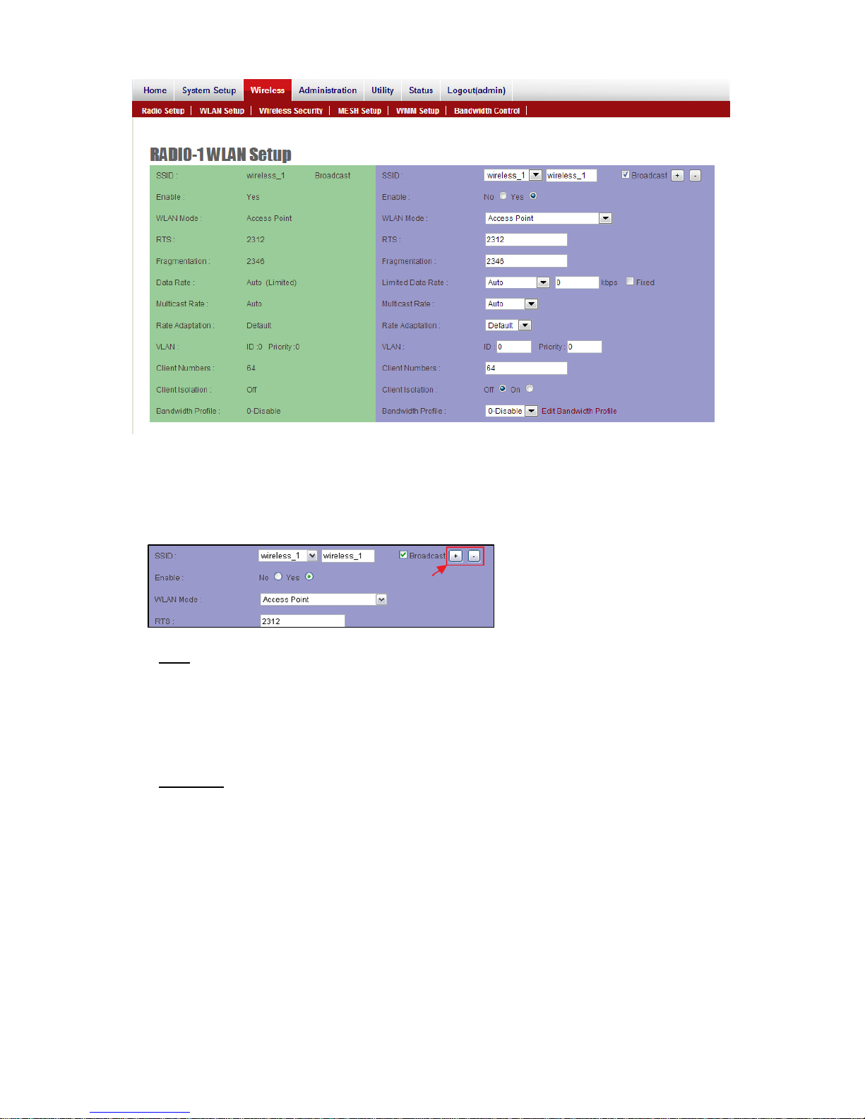
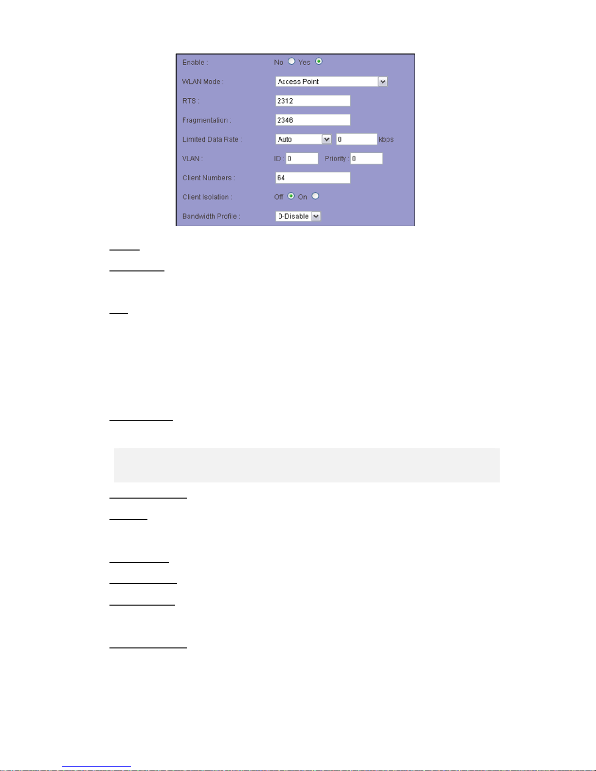
Figure 99 Wireless Settings
Each physical radio interface supports up to 16 virtual WLAN AP setting. User can add or delete a
virtual AP by click the “+” or “-” button on top of the very right side of setting block.
SSID A service set identifier (SSID) is a name that identifies a particular 802.11 wireless LAN. A
client device receives beacon messages from all access points within range advertising their
SSIDs. The client device can then either manually or automatically select the network with which
to associate.
Broadcast Network administrator can choose broadcast beacon messages of a virtual AP by
checking the broadcast block.
Page 29
Chapter 5 Management Page 24
EnableNetworkadministratorcanalsodecidefunctioningofvirtualAPorletitidle.
WLAN Mode Radios support “Access Point”, “Wireless Station”, “Access Point (WDS Support)”
and “Wireless Station (WDS Support)” mode to meet various network scenarios.
RTS “Request to send” is the optional mechanism used by the 802.11 wireless networking
protocol to reduce frame collisions introduced by the hidden node problem. Set the packet size to
trigger RTS/CTS enable. This is normally set in AC side only because the hidden station problem
does not exit from the perspective of the AP. RTS Threshold can be set between 1 and 2312
bytes.
Fragmentation Set the packet size to activate fragment ation. Fra gment ation threshold can be set
between 1 and 2312 bytes.
Note: Fragmentation setting will be automatically disabled, once the frame aggregation is
enabled.
Limited Data Rate Limit the wireless dat a link rate to enhance the stability of data transmission.
VLAN ID In order to create a wireless VLAN environment, each virtual AP can conform to an
802.1Q VLAN tag ID.
VLAN Priority Each VLAN ID can be gave a priority number (from 0 to 7) for dat a process priority.
Client Numbers Limit the maximum number of associate client devices.
Client Isolation Client isolation will protect the privacy of each connecting client from searching in
a wireless LAN.
Bandwidth Profile Choose a band wid t h co ntrol profile for virtu al AP interface. (About the detail of
bandwidth profile, please refer to the bandwidth control setup in coming pa ges.)
Page 30

Chapter 5 Management Page 25
Wireless Security
Figure 10 Wireless Security Settings
SSID User can choose a specific virtual AP to assign a security type of wireless link.
MAC Filter MAC filter provides allow or deny MAC table for administrator to access control of AP
by insert a MAC address of client device. When running allow mod e, only the MAC address which
showing on the table will be accept for wireless connectivity. When running deny mode, MAC
address which showing on the table will be blocked from wireless connectivity. The table can be
configured 32 MAC address at most of each virtual AP interface.
Security Comprehensive security settings are available on system in this menu. These include
Page 31

Chapter 5 Management Page 26
WEP Keys and WPA+WPA2-PSK. Details of each type of security are in appendix. The security
settings are independent between each virtual AP interface.
WEP System supports 64-bit, 128-bit and 152-bit WEP key in both ASCII and HEX format. Do
make sure the correctly number of digits/characters and format of WEP key as shown in the table
are entered. Note that in HEX format, HEX number cannot start with “0”.
Number of digit/character ASCII HEX
64-bit 5 10
128-bit 13 26
152-bit 16 32
WPA+WPA2-PSK The AP support WPA+WPA2-PSK (WPA-Personal) in security.
WPA+WPA2-PSK (Pre-shared key) mode is designed for home and small office networks and
doesn't require an authentication server. Each wireless network device authenticates with the
access point using the same 256-bit key.
TKIP Temporal Key Integrity Protocol: A 128-bit per-packet key is used, meaning that it
dynamically generates a new key for each packet. Used by WPA.
CCMP An AES-based encryption mecha nism that is stronger th an TKIP. Sometimes referred to as
AES instead of CCMP. Used by WPA2.
Both TKIP and CCMP encryption are available for WPA+WPA2-PSK. Pre-shared key of 8 to 63
characters are required. Group Rekey Interval can be set up to 65536 seconds.
MESH Setup
This feature is just applied to the JetWave 2800-M Series.
Page 32

Chapter 5 Management Page 27
Figure 20 Wireless MESH Settings
The MESH Setup page contains two major setting category :MESH Global Setting Setup and
RADIO MESH Setup.
MESH Global Setting:
This page allows you to configure the global settings for MESH mode.
MESH ID & SubID A five digit number to identify a specific MESH group. System will
recognize aneighbor MESHdevice asthe same groupwhen both MESH ID andSubID
arecoincident.
Page 33
Chapter 5 Management Page 28
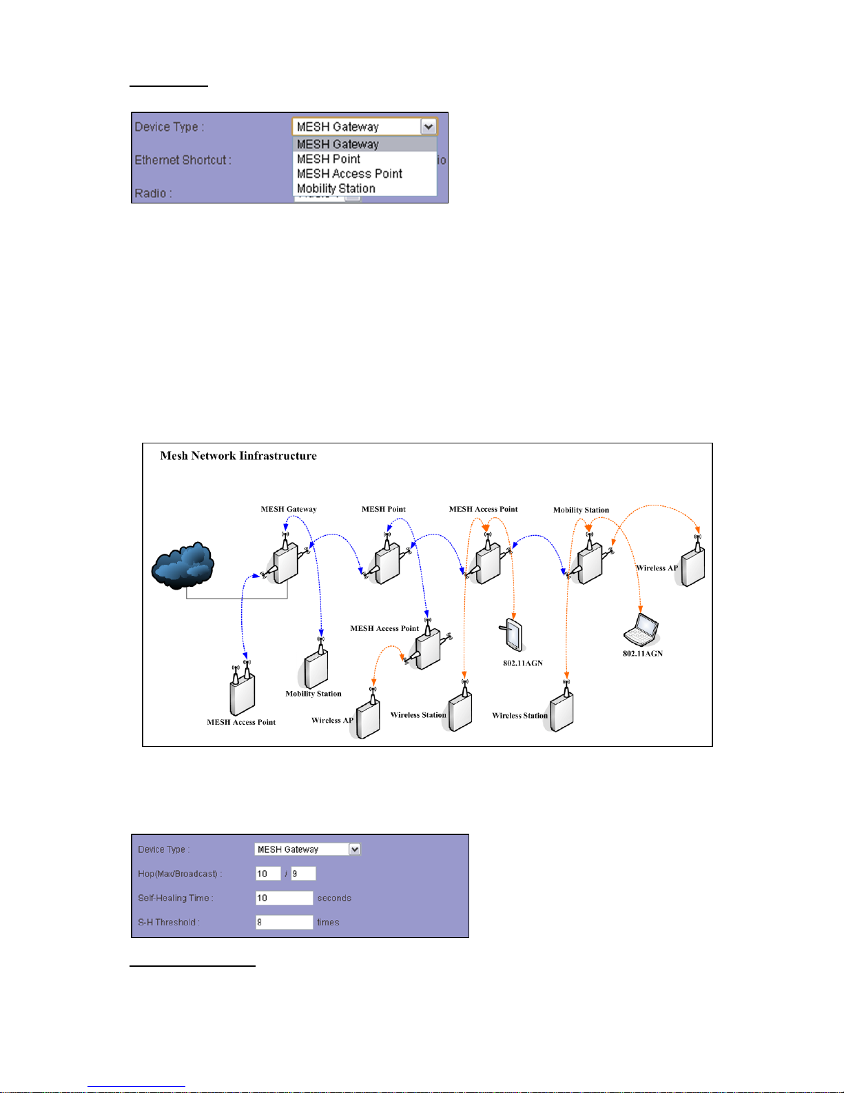
Device Type:TherearefourMESHtypesoptionalforadevicewhichisrunningMESHmode:
MESH Gateway
A gateway MESH node of a MESH group, it will control the registration of all MESH nodes in group.
There must be a MESH Gateway node in a MESH group.
MESH Point
A MESH node relays data from all MESH neighbor nodes.
MESH Access Point
A MESH node who works not only relaying MESH backbone data flow but also service Mobility
Station or 802.11AGN.
Mobility Station (Mobility license authenticate)
A MESH node that is able to do fast roaming between MESH Access Points under MESH group
mobility service coverage.
MESH Gateway peculiar configuration
Following configurations are available only when device type is in MESH Gateway mode:
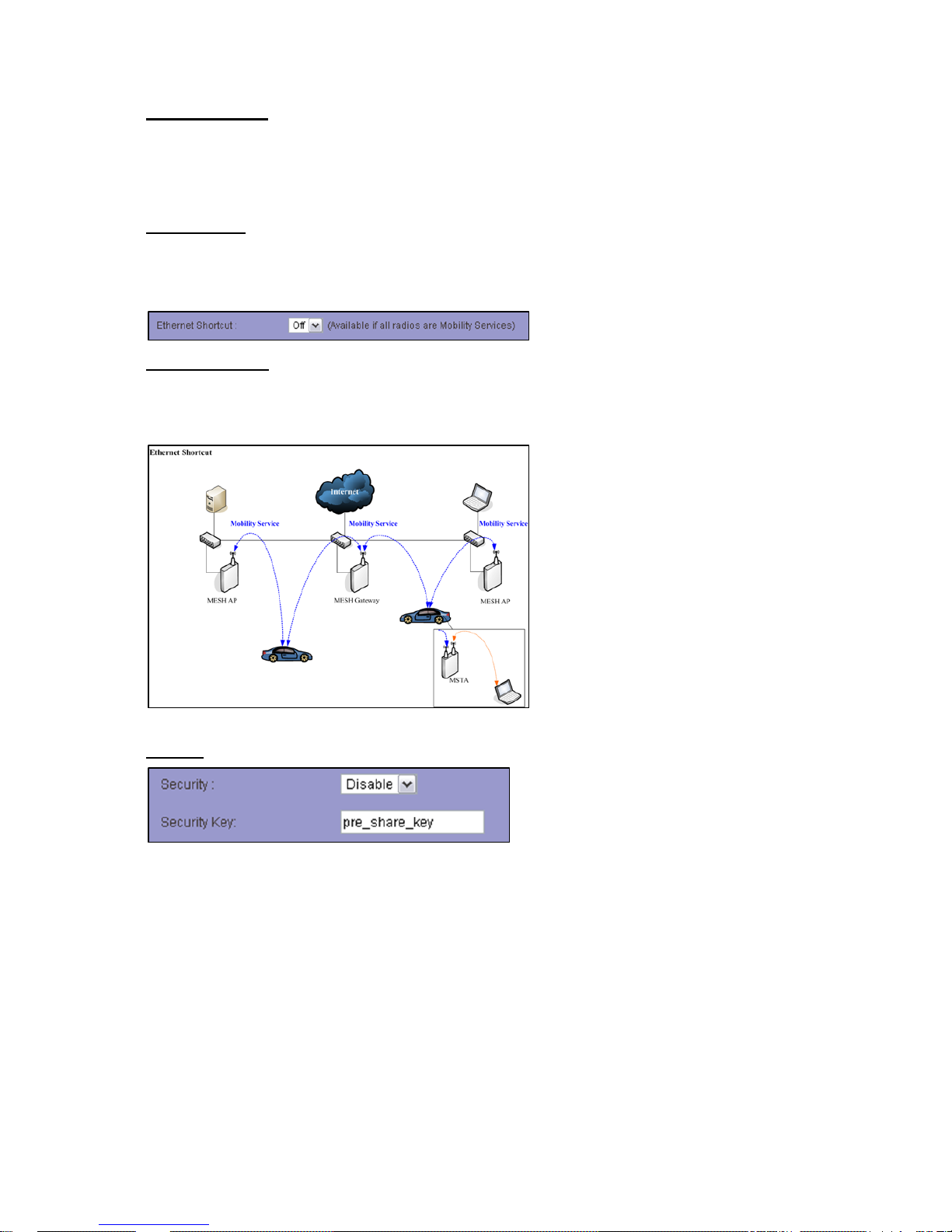
Hop(Max/Broadcast)The maximun hops count of MESH network scale and broadcast packet. (Only
available on MESH Gateway)
Page 34
Chapter 5 Management Page 29
Self-Healing Time Each MESH node which is trying to join a MESH group mu st to register with MESH
Gateway node. After the registration is confirmed, the MESH node can function its own role in group.
Once a registered node is disconnected from group, the MESH system will wait for a period of time to
delet registration information.
S-H Threshold To maintain a MESH network, MESH neighbors will keep sending management pa cket
to update the best routing of data stream. Once the lossing management packet number is reaching a
Self-Healing threshold number , the system will determine the link is loss.
Ethernet Shortcut A inde pendent confi guration for specifi c network MESH which all MESH n odes are
connected by wire. The Ethernet Shortcut is limited by all radios on device should be Mobility Service
in WLAN Mode.
Security
MESH wireless link will be protected by a pre-share key setting, since the security is enabled in global
MESH setting. This pre-share key setting should be synchron ous in a MESH group.
MESH Radio Setup
Following parameters areworking on a specific radio interface whichuser chooses firstin
“Radio”:
Page 35
Chapter 5 Management Page 30
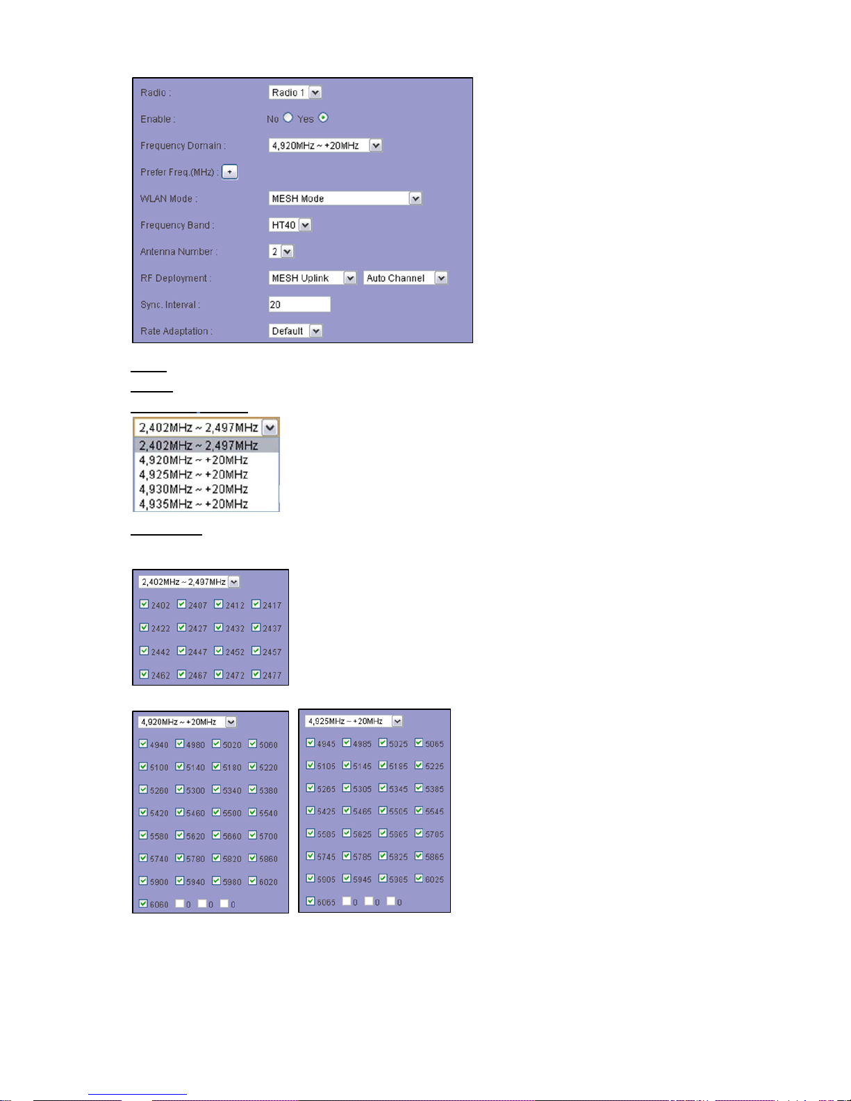
Radio Select a radio that you are going to configure.
Enable Enable or disable the selected radio interface.
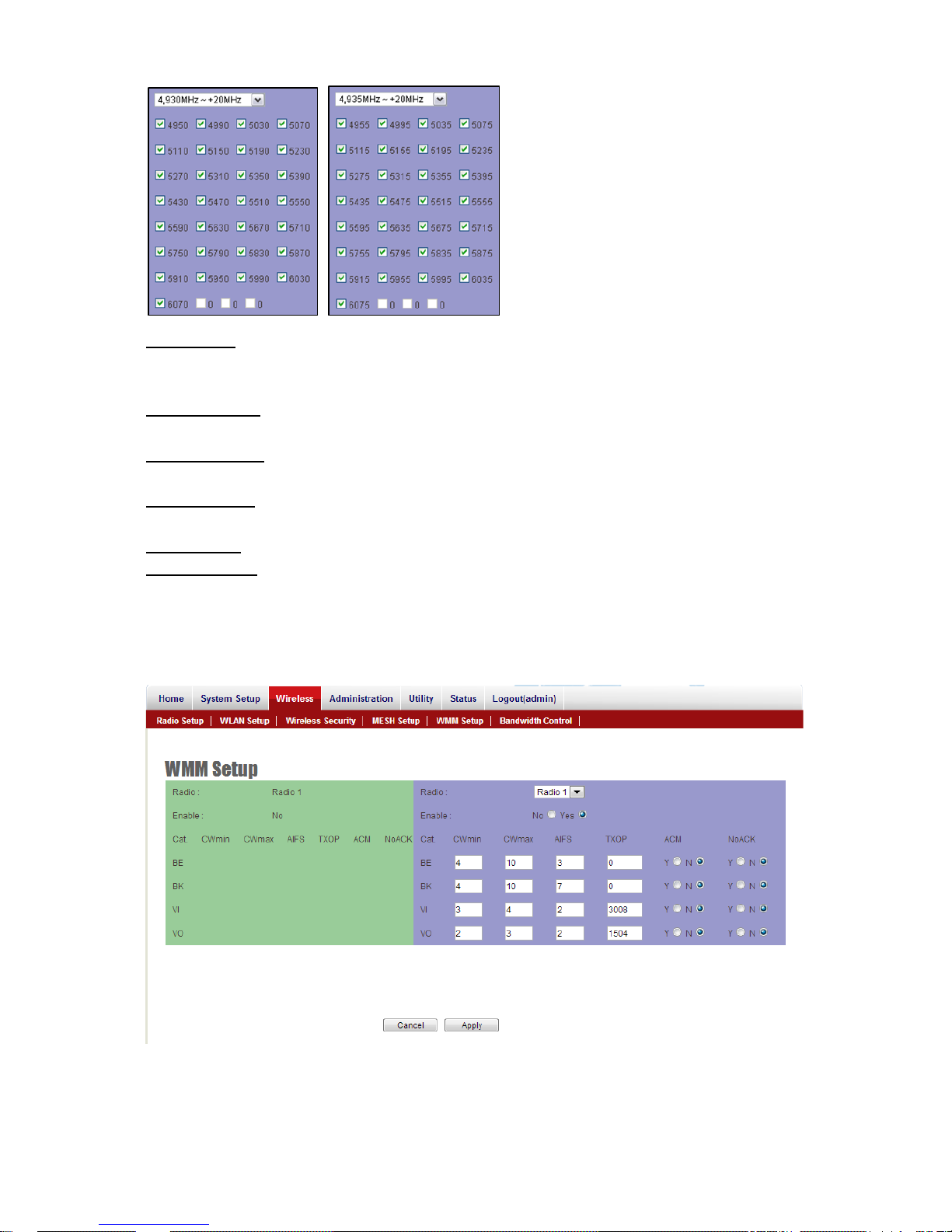
Frequency Domain There are 5 frequency domains optional for each radio inte rface.
Prefer Freq User can select few prefer frequencies for Mesh to scan instead of scan all available
channels in frequency domain.
Page 36
Chapter 5 Management Page 31
WLAN Mode Radios support “Access Point”, “Wireless Station”, “Access Point (WDS Support)”,
“Wireless Station (WDS Support)”, “MESH Mode” and “Mobility Mode” mode to meet various network
scenarios.
Frequency Band Choose a HT20 (channel bandwidth: 20MHz) or HT40 (channel bandwidth: 40MHz)
radio frequency for signal transmission.
Antenna Number System completes 802.11n 1x1 1-steram and 2x2 2-stream for antenna attached.
The maximum data link rate at 1-steram and 2-stream will be 130Mbps and 300Mbps.
RF Deployment 3 radio operating mode: “Mesh Uplink” “Mesh Downlink” and “Mobility Service” to
define various radio behavior .
Sync. Interval To define a time period for Mesh nodes synchronizing path information to each other.
Rate Adaptation To define the up and down gradient of data rate when a data rate is auto or limited.
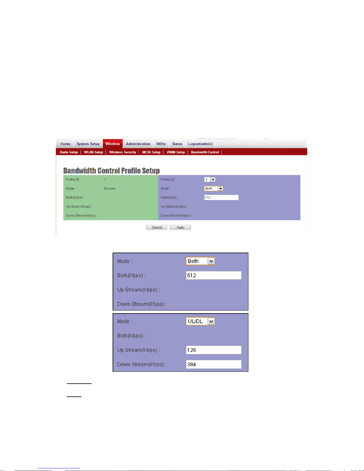
WMM Setup
Figure 21 Wireless WMM Settings
Page 37
Chapter 5 Management Page 32
Wi-Fi Multimedia (WMM) is a Wi-Fi Alliance interoperability certification, based on the IEEE
802.11e standard. It provides basic Quality of service (QoS) features to IEEE 802.11 networks.
WMM prioritizes traffic according to four Access Categories (AC) - voice, video, best effort, and
background. It is suitable for simple applications that require QoS, such as V oice over IP (VoIP) on
Wi-Fi phones (VoWLAN).
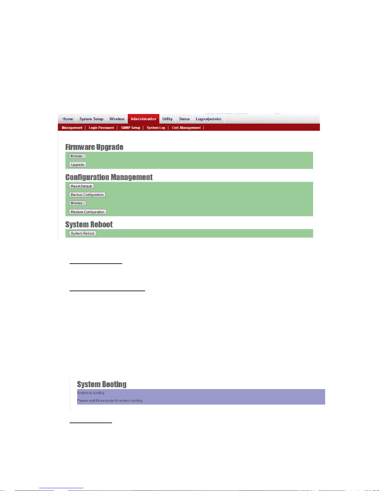
Bandwidth Control Profile Setup
Figure 22 Bandwidth Control Profile Setup
Profile ID There are 20 bandwidth control profiles can be configured for administration.
Mode Downstream and upstream data rates for subscriber or the client devices connecting to AP
can be defined here. There are two bandwidth limit types in system. Both mode (UL+DL Limit
Rate) consolidates download and upload rate of each single client connection. UL/DL mode
Page 38

Chapter 5 Management Page 33
(UL/DL Limit Rate) specifies download and upload rate of client connections. Once the bandwidth
limit is enabled, the limitation applies to all clients that connect to the AP.
Page 39
Chapter 5 Management Page 34
Administration
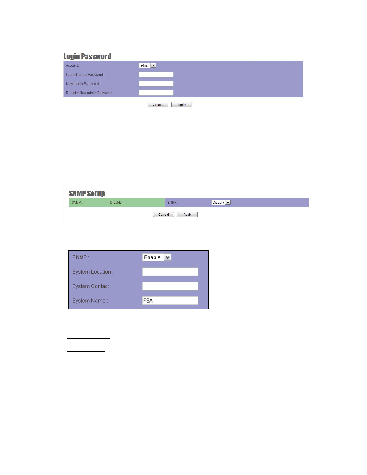
JetWave 2800 series provides system management in menu partition: Administration, Which
includes configuration file management, password maintaining and SNMP setup.
Management
Figure 23 Administration
Firmware Upgrade Administrator can upload a new firmware file to device to keep system
running by the latest bug fixed version of firmware.
Configuration Management
Administrator would like to save the configuration of device to local PC by click “Backup
Configuration”. Once hardware damage happened, administrator can “Restore Configuration” a
saved configuration file to a new hardware without any reconfiguration.
“Reset Default” allows administrator to reload the system to factory default. After click Reset
Default, the system will reboot automatically. You will see below screen. Please wait and connect
it again by Default IP Address (192.168.1.1).
System Restart Click the “System Reboot” button will help to warm start the system.
Page 40
Chapter 5 Management Page 35
Login Password
System allows administrator to change the “admin” and “user” login password in menu partition:
“Login Password”.
SNMP Setup
JetWave 2800 series supp ort both SNMP V2 and V3. The configurable items show below:
System Location A description notes the device location.
System Contact A description notes the device maintaining information.
System Name A description notes the given name of device.
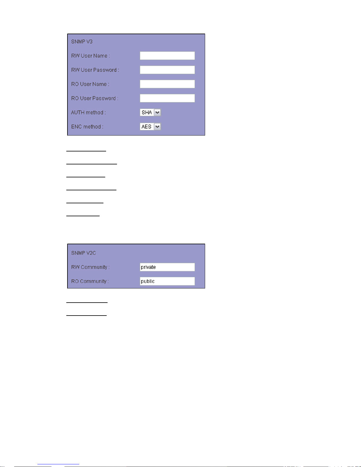
SNMPV3
Page 41
Chapter 5 Management Page 36
RW User Name Read and write authority login ID.
RW User Password Read and write authority login password.
RO User Name Read only authority login ID.
RO User Password Read only authority login password.
AUTH method Choose the user authentication method.
ENC method Choose the SNMP data encryption method.
SNMP V2C
RW Community Read and write authority community stream.
RO Community Read only authority community stream.
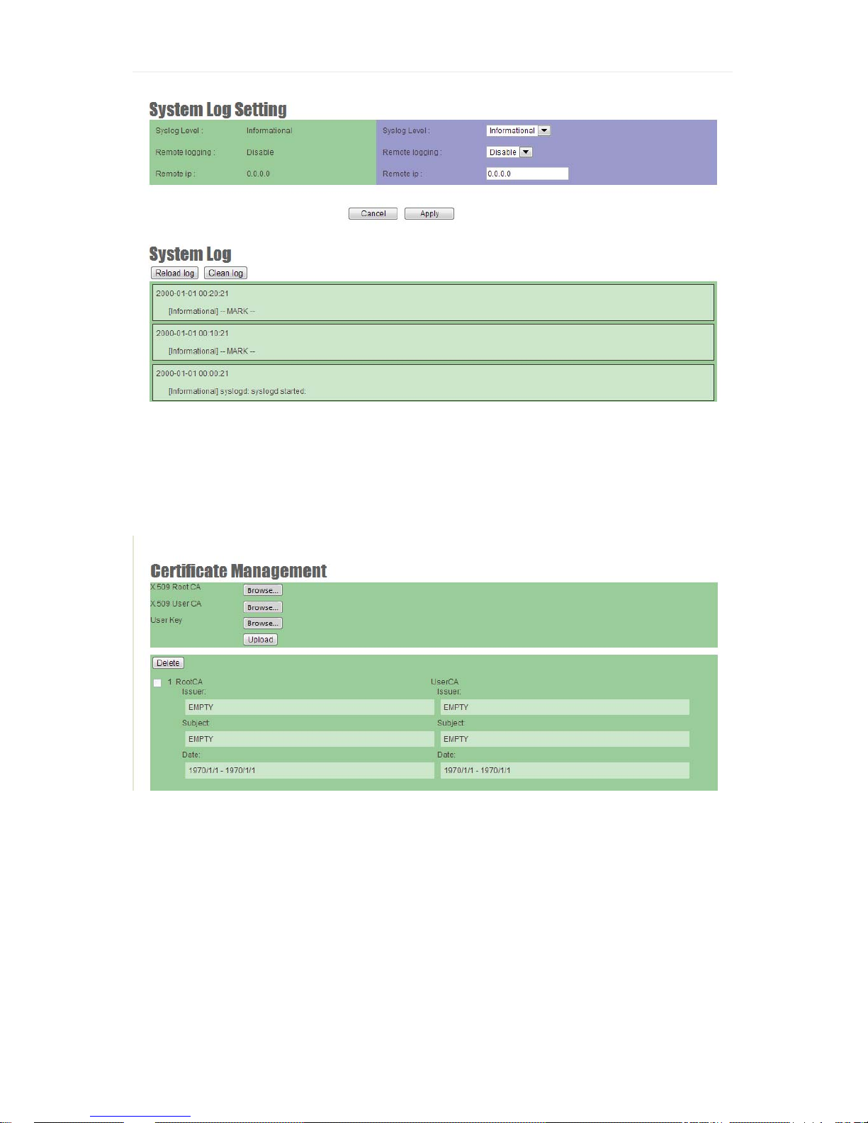
System Log Setting
Page 42
Chapter 5 Management Page 37
Figure 24 System Log Setting
Certificate Management
Figure 24 Certificate Management
Page 43
Chapter 5 Management Page 38
Utility
JetWave 2800 series provide various software utilities helping administrator to do the network
status survey and diagnostic.
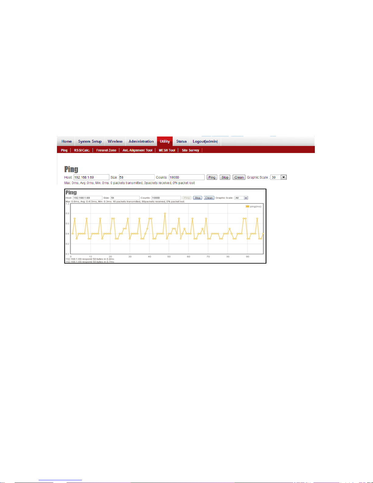
Ping
“Ping” allows you to know the alive status of the remote unit easier.
Figure 24 Ping Utility
Graphical display helps administrator to get the responding time changes of target IP address.
Insert the remote host IP address, packet size an d number in field than press Ping, system will
show the result on page. The result presenting can be adjusted by different choosing of graphic
scale.
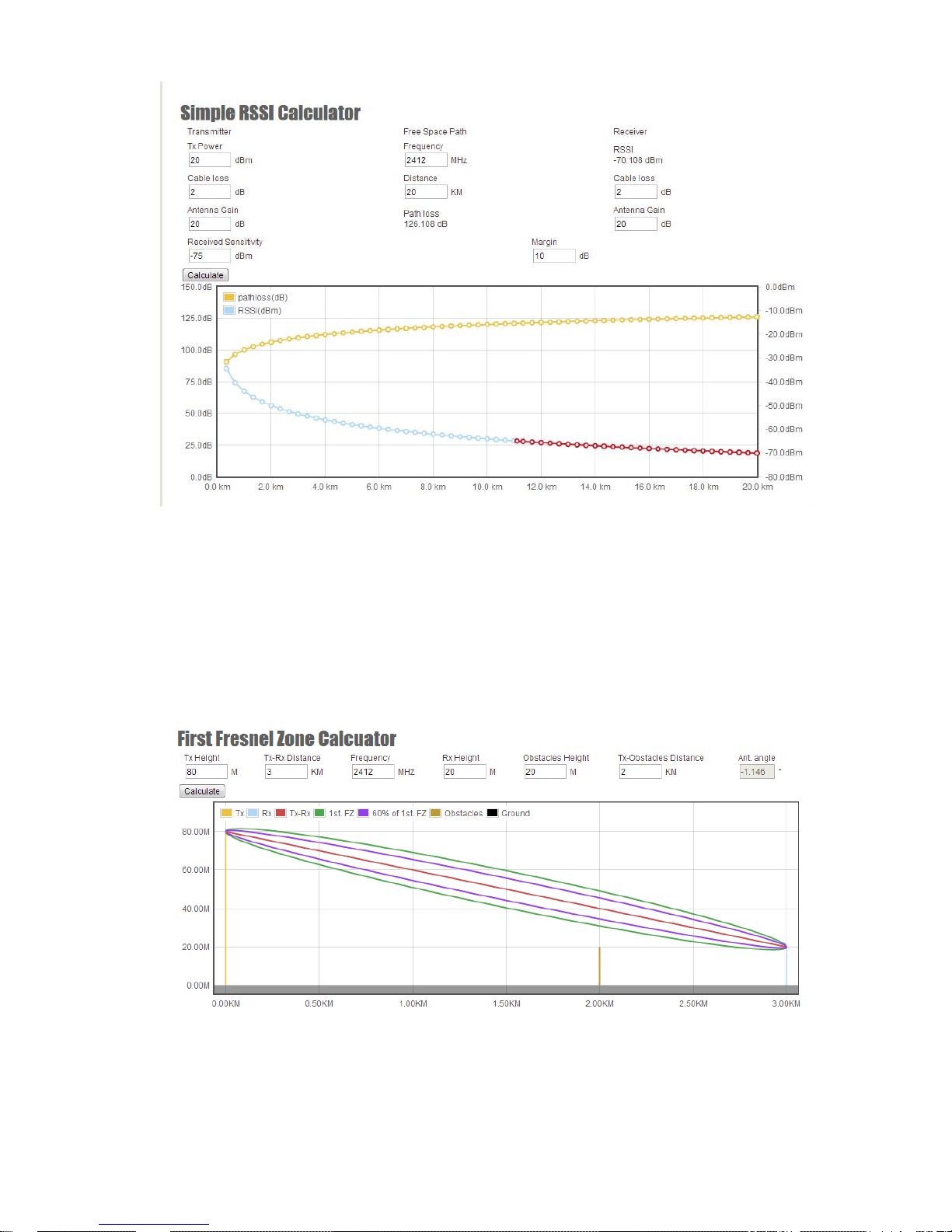
RSSI Calculator
Simple RSSI Calculator helps to estimate a possible RSSI and path loss by known device Tx
power (transmission power), cable loss, antenna gain and frequency both transmitting and
receiving side. Graphic displaying shows changes of path loss and RSSI.
Page 44
Chapter 5 Management Page 39
Figure 24 Simple RSSI Calculator
First Fresnel Zone Calculator
The First Fresnel Zone Calculator is a tool that helps you to estimate the possible obstruction from
existing object between two devices before the wireless installation. An antenna angle cal culation
can also help you to aligning the vertical angle of the directional antenna.
Figure 25 First Fresnel Zone Calculator
Page 45
Chapter 5 Management Page 40
Antenna Alignment Tool
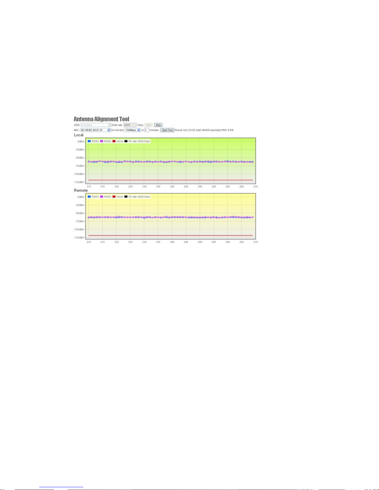
In order to lift efficiency of antenna aligning, JetWave 2800 series provide a software alignment
tool helping the installers to align and check the antenna directions.
Antenna Alignment Tool will require triggering the function both access point and wireless station
(AP Client) side. It means that both access point and wireless station (AP Client) side should be
the JetWave 2800 series product, otherwise, the function doesn’t get properly use.
Figure 25 Antenna Alignment Tool
Choose the SSID which you are going to do the antenna aligning and click the Start button both
access point and wireless station (AP Client) side to start the antenna alignment. You will able to
see the RSSI changes in figure. Try to adjust the directional antenna’s horizontal and vertical
angle to get the best RSSI level.
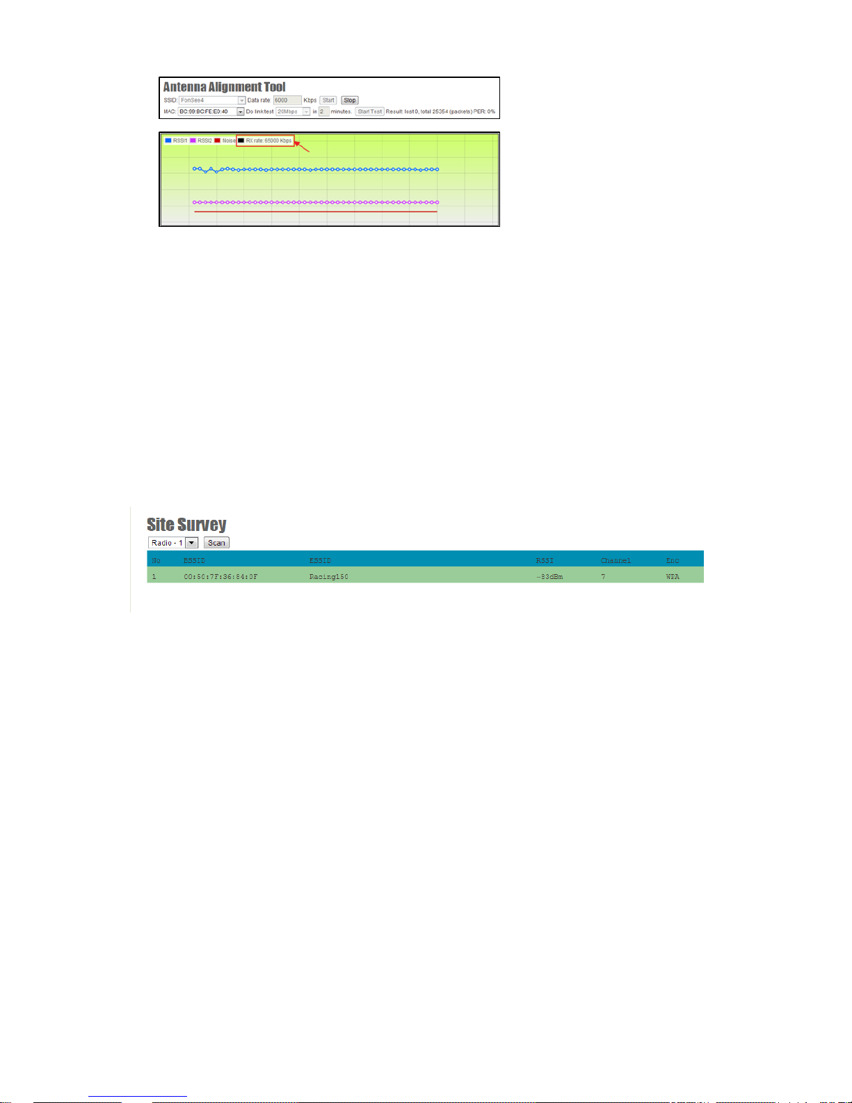
Link Test
A Link Test is additional tool base on Antenna Alignment Tool active status. When you start the
Antenna Alignment Tool, you may set a target throughput to active the Link Test to estimate the
packet error rate.
Choose a target throughput and test duration than click Start Test button. System will generate a
test data transmission to calculate the packet error rate.
Page 46
Chapter 5 Management Page 41
An Rx rate shows the best data rate you can reach under the current RSSI level.
Link Test Tool can also help you to do the fine tuning of your antenna direction.
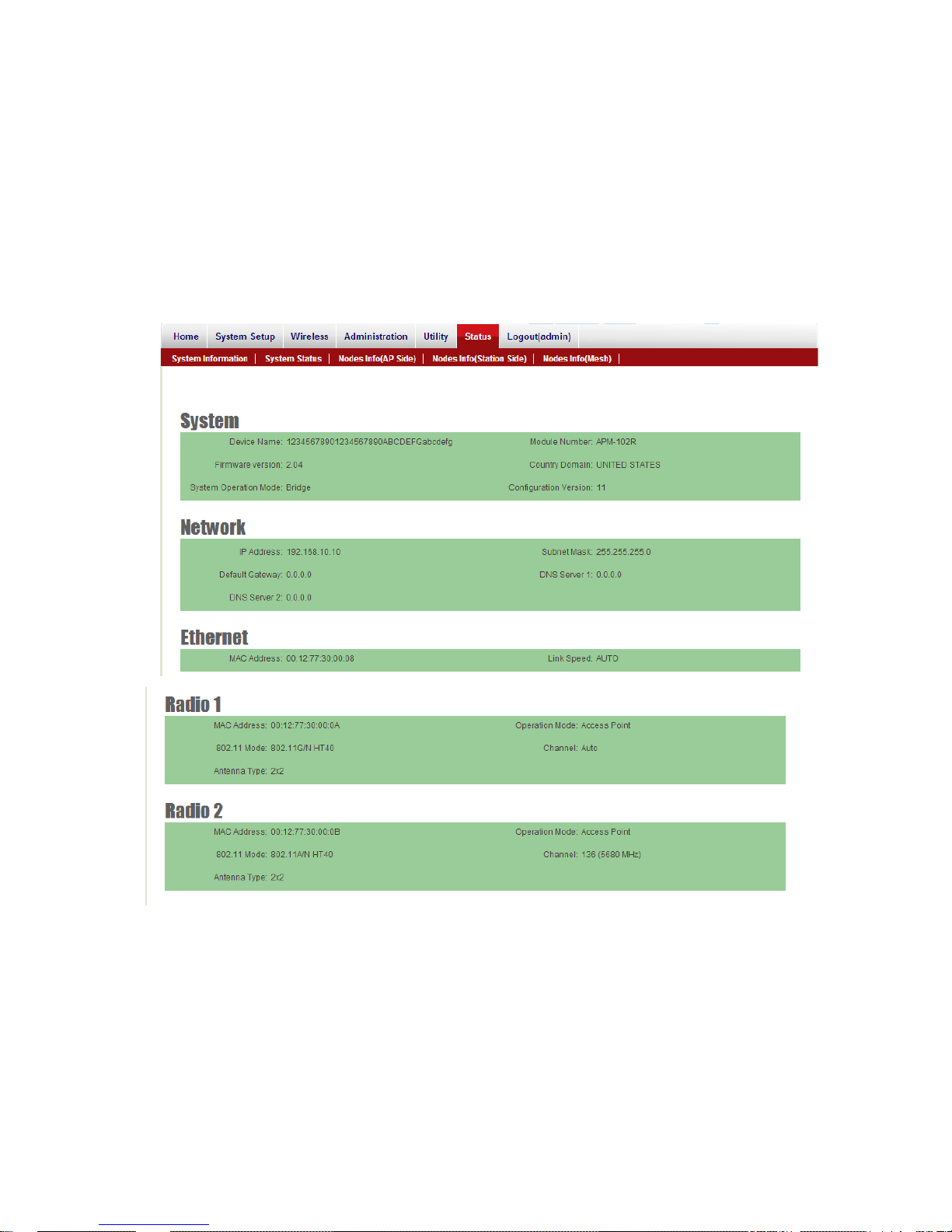
Site Survey
In wireless site survey, system provides a signal scan function to detect any available wireless
signal around the AP. It will help AP installer to clarify the environment. Choose a radio interface
which you are going to do the survey on device and click Scan button. After few secon ds, system
will show the APs around the device.
Figure 26 Site Survey
Page 47
Chapter 5 Management Page 42
Status
System Information
System Information summarizes all the configuration and hardware information of the device. The
information includes System Information, Network Addresses, Ethernet Port and Radio Cards
Information.
Figure 27 System Information
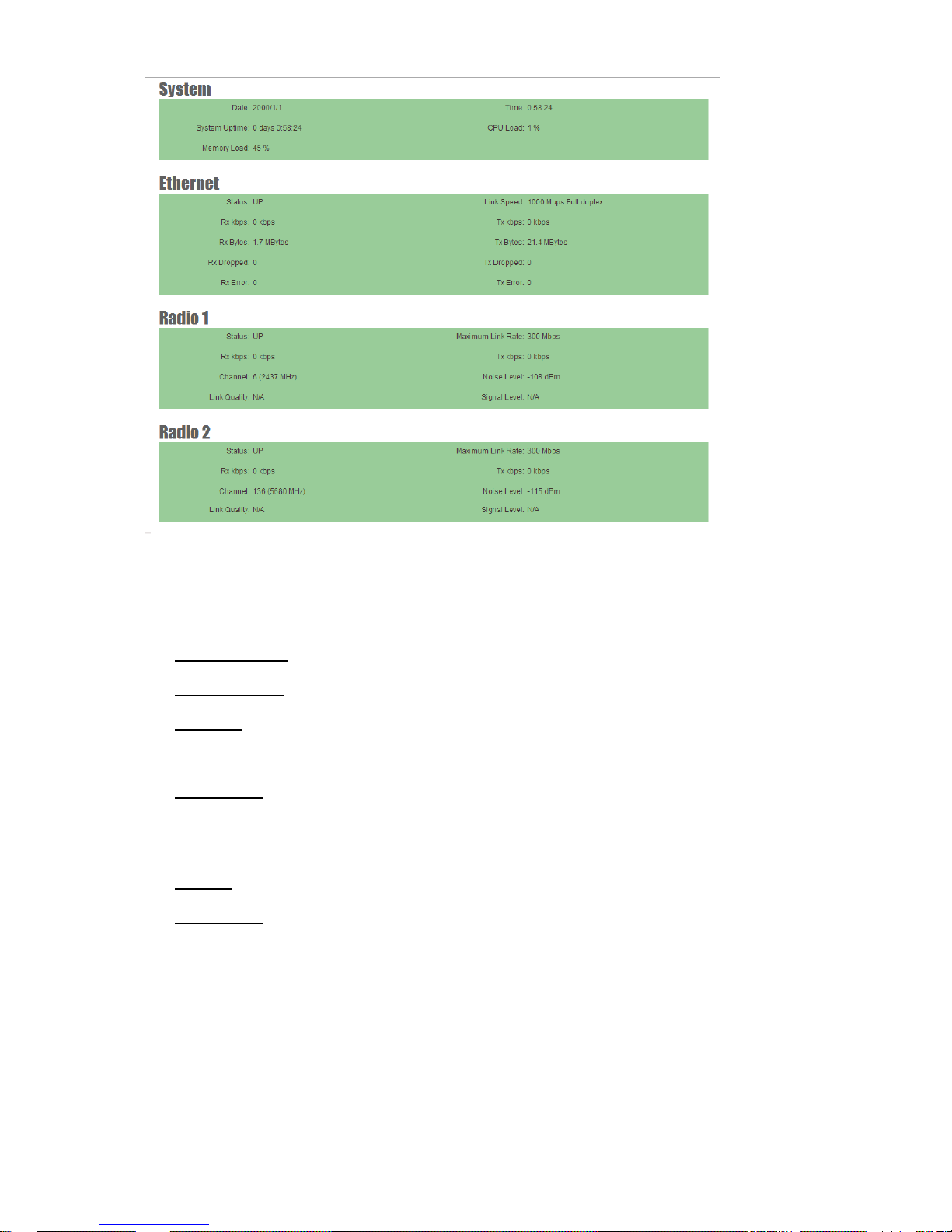
System Status
Page 48
Chapter 5 Management Page 43
Figure 27 System Status
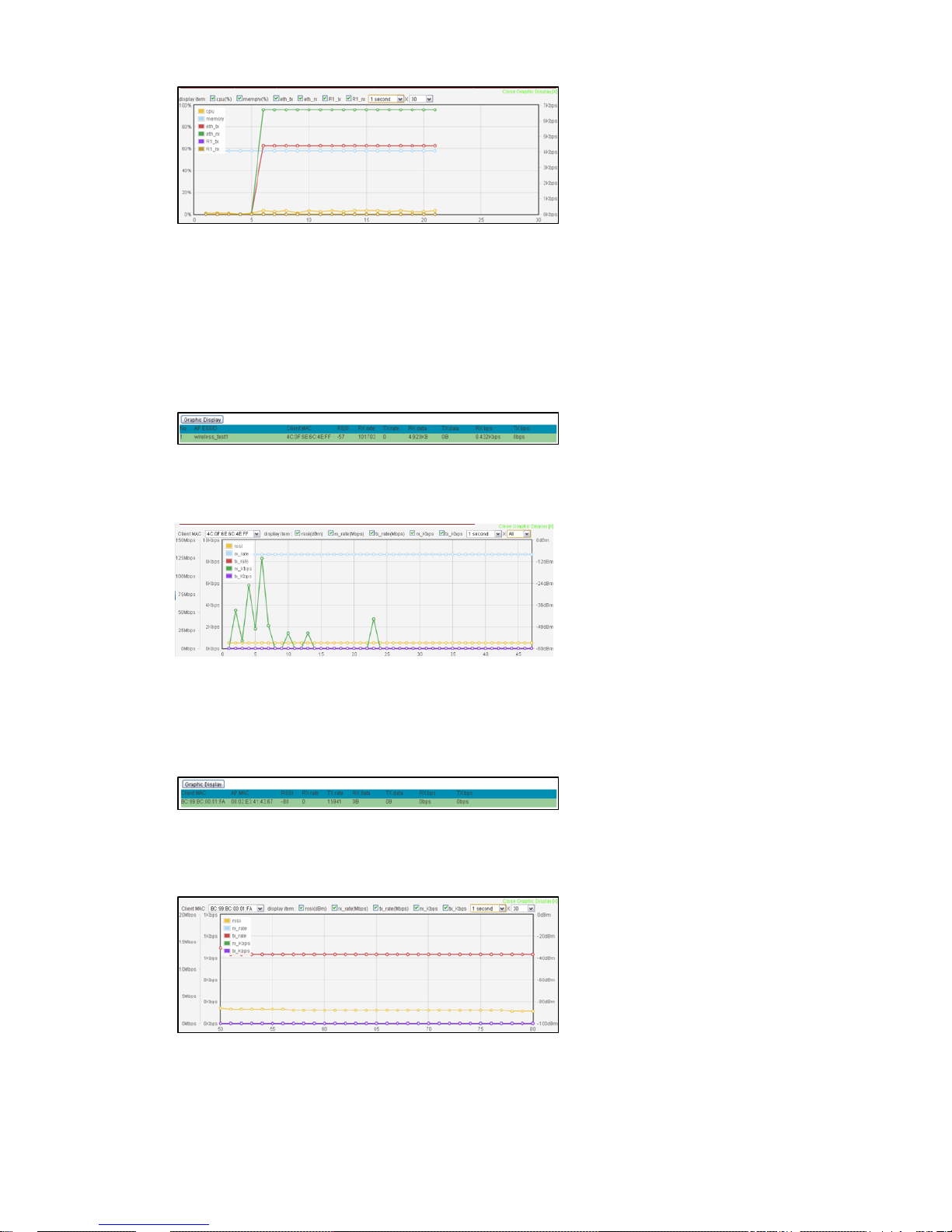
Real-time link statuses of all interfaces are shown in the menu.
System Up Time Display how long the AP has been operating since last boot-up.
Interface Status Indicate the interface is ENABLE or DISABLE.
Link Rate Data Link Rate here indicates the maximum transmission rate available, and can be
used as an indication of link quality.
Link Quality A Calculation of RSSI, signal and noise level to indicate the quality of the
communication link in percentage.
Channel The channel used by the wireless interface.
Signal Level A -70 ~ -50dBm signal level is recommended for a good connection. Too low a
signal, the wireless link between AP and AC cannot be established. Too high a signal level, the
power amplifier at the receiver might be forced to operate in saturation region and distorts the
signal waveform.
Page 49
Chapter 5 Management Page 44
In order to help user’s reading of the changes, system also provide a graphic inte rface to trace the
items’ changes. Click the Graphic Display button on the top left of the page, graphic mode will
show on your browser.
Connecting Nodes Information
All the connecting clients’ MAC add ress will be displa y in Connecting Nodes Information, incl uding
signal and data rate. The result shows information only when WLAN was configured as Access
Point mode.
Graphic display is also available for observing the changes.
Figure 27 Connecting Nodes Information
Connecting AP Information
In the “Connecting AP Information” page, RSSI, Rx rate, Tx rate and etc. are provided for
verification of wireless link status.
Figure 27 Connecting AP Information
Graphic display is also available for observing the changes.
Page 50
Chapter 5 Management Page 45
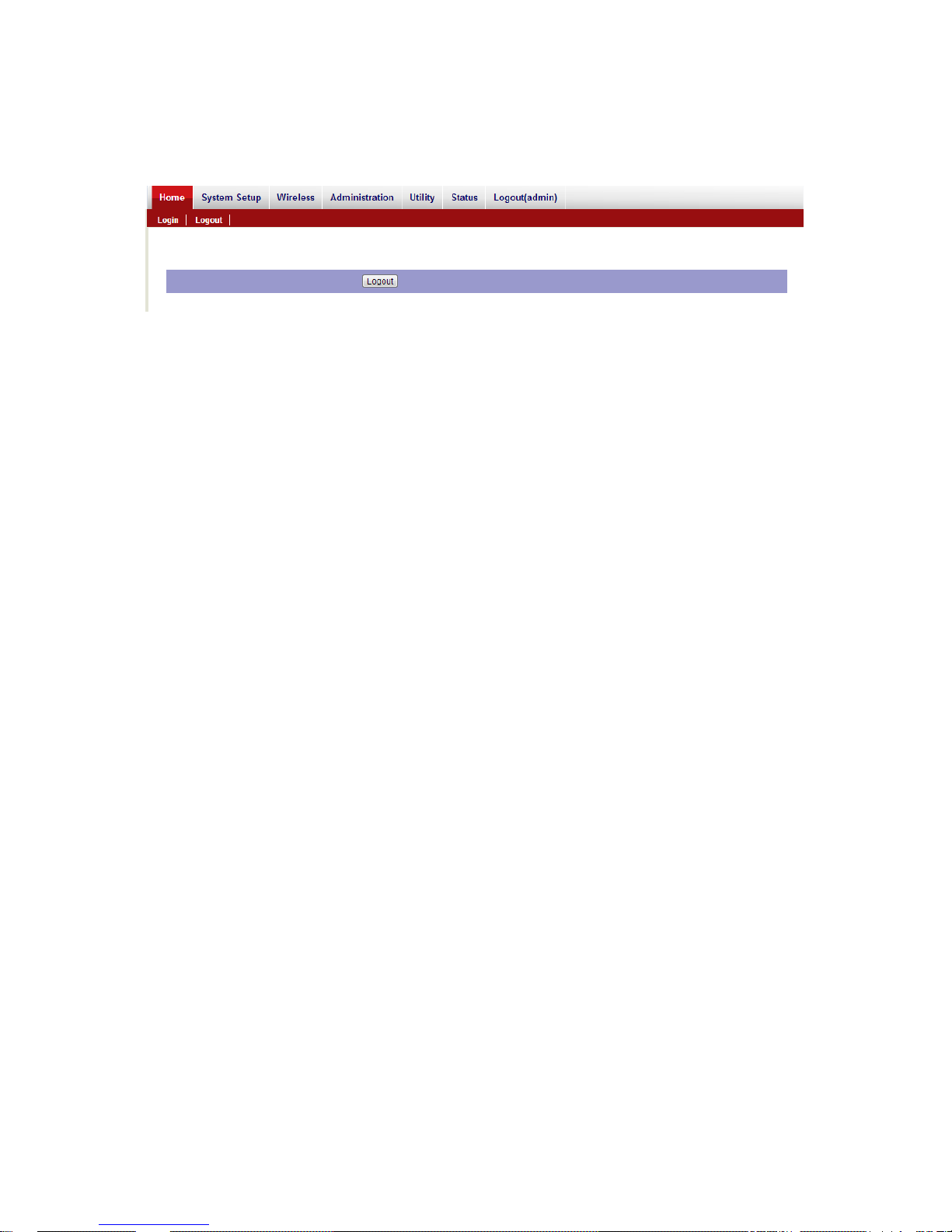
Logout(admin)
Figure 28 Logout
Page 51
Chapter 5 Management Page 46
Chapter 4 Utility
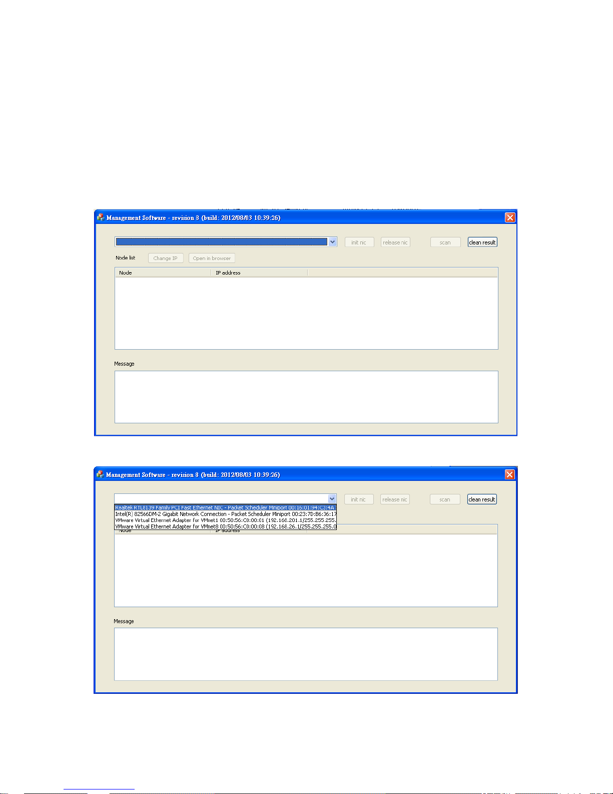
JetWave 2800 Search Utility
The utility provides you convenient tool to scan the network and then you can “Change IP” or open its
Web GUI in “Open in browser”.
Step 1: Open the Utility
Step 2: Select the correct NIC (Network Interface Card) from the NIC list.
Page 52
Chapter 5 Management Page 47
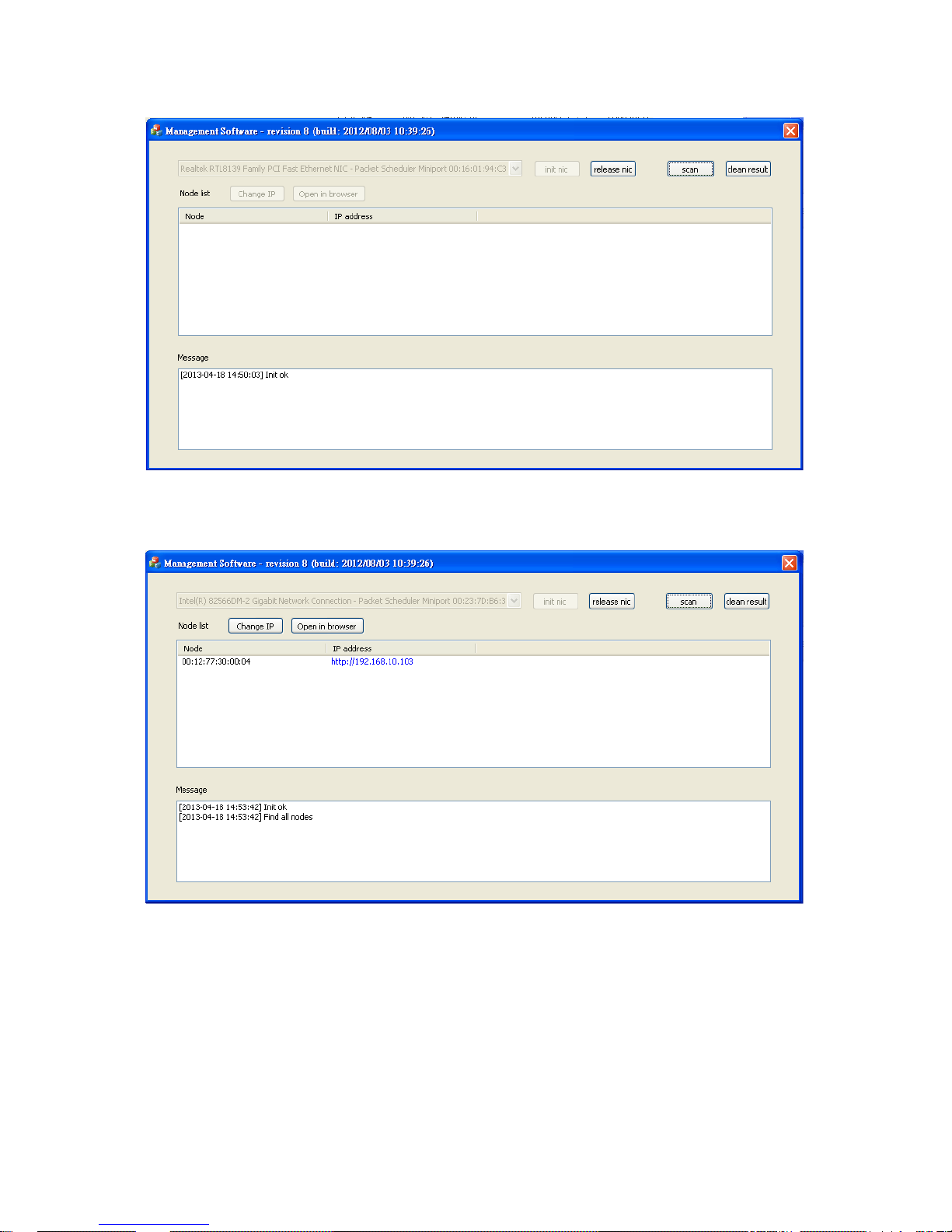
Step 3: Click “int. nic”, and then you can see the “[Time] Init. ok” in the Message field.
Step 4: Click “SCAN” to scan the network. The Nodes and its IP address can be found and listed in
Node list. “Find all nodes” message means all the nodes are found and the process is terminated.
Page 53
Chapter 5 Management Page 48
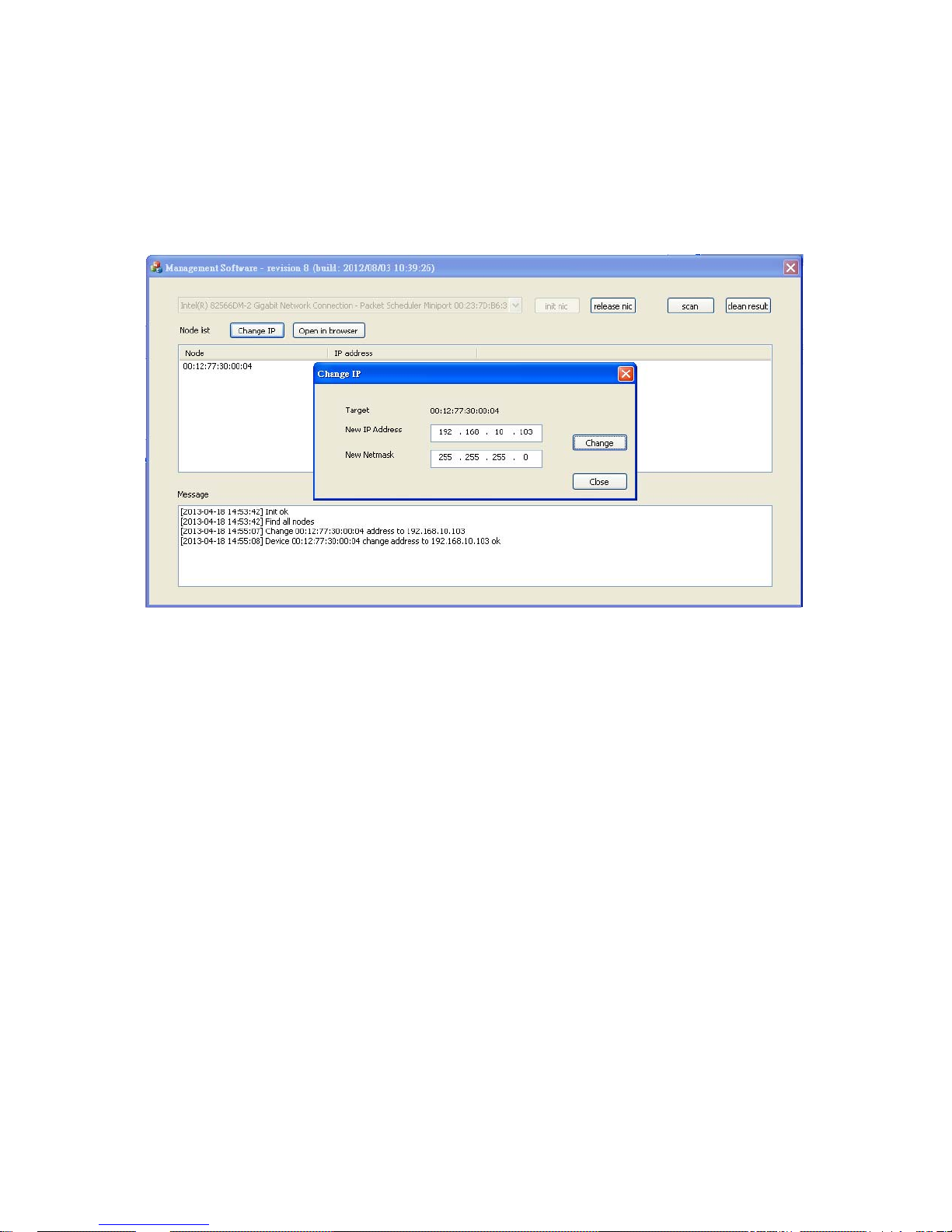
Step 5: Af ter scan the network, there are 2 available commands, “Change IP” and “Open in bro wser”.
Select the AP and click “Open in bowser”, then you can access the web management interface.
Select the AP and click “Change IP”, you can see the following popup window, “Change IP”. Change
the IP address and Netmask, then click “Change” to apply the new settings.
Page 54
Chapter 6 Troubleshooting Page 49
Chapter 5 Troubleshooting
This chapter provides troubleshooting procedures for basic problems with the JetWave 2800. For
warranty assistance, contact your service provider or distributor for the pro ce ss.
Q 1. How to know the MAC address of JetWave 2800?
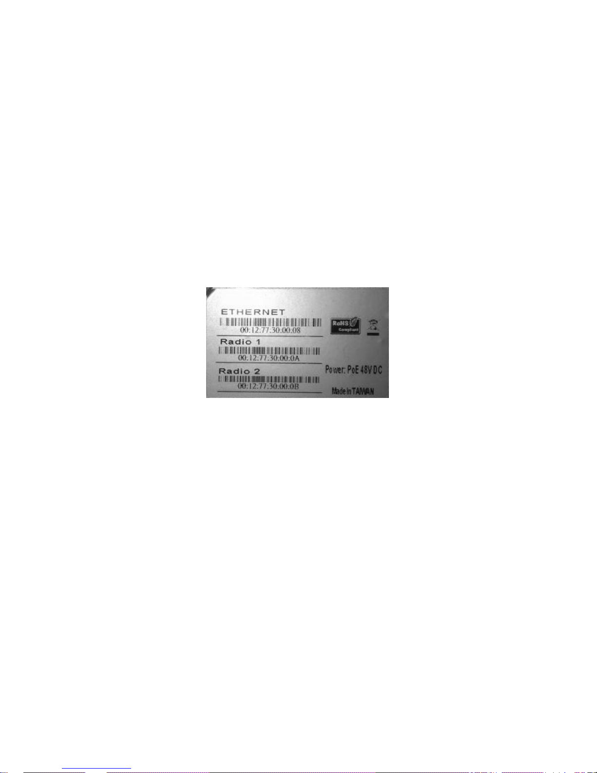
MAC Address distinguishes itself by the unique identity among network devices. There are two
ways available to know it.
• Each device has a label posted on the back of the AP. There are MAC address for Ethernet
and Radio cards. Please refer below.
Figure 11 MAC Address
• On the JetWave 2800 Web-based management interface, you can view the MAC Address
from “Status” -> “System Status”.
Q 2. Wha t if I would like to reset the unit to default settings?
You may restore factory default settings in “Management” from “Administration”.
Q 3. Wha t if I would like to backup and retrieve my configuration settings?
You may do the backup by generating a configuration file or retrieve the settings you have backed
up previously in “Configuration Management” from “Administration”.
Q 4. Wha t if I can not access the Web-based management interface?
Please check the followings:
• Check whether the power supply is OK; Try to power on the unit again.
• Check whether the IP address of PC is correct (in the same network segment as the unit);
Page 55

Chapter 6 Troubleshooting Page 50
• Login the unit via other browsers such as Firefox.
• Use JetWave Viewer to scan the AP and modify the IP address.
Q 5. What if the wireless connection is not stable after associating with an AP under wireless
client mode?
• Since the JetWave 2800 comes without built-in directional antenna, it is recommended make
the external antennas’ face to the direction where the AP is to get the best connection quality.
• Check the “Distance (x100m)” setting in “Radio Setup”. Correct distance can help improve
the transmission quality.
• In addition, you can start “Site Survey” in “Utility” to check the signal strength. If it is weak or
unstable (The smaller the number is, the weaker the signal strength is.), please join other
available AP for better connection.
Page 56

Appendix B. GPL Declamation Page 51
Appendix A. ASCII
WEP can be configured with a 64-bit or 128-bit Shared Key (hexadecimal number or ACSII). As
defined, hexadecimal number is represented by 0-9, A-F or a-f; ACSII is represented by 0-9, A-F, a-f or
punctuation. Each one consists of two-digit hexadecimal.
T able 2 ACSII
ASCII
Character
Hex
Equivalent
ASCII
Character
Hex
Equivalent
ASCII
Character
Hex
Equivalent
ASCII
Character
Hex
Equivalent
! 21 9 39 Q 51 i 69
" 22 : 3A R 52 j 6A
# 23 ; 3B S 53 k 6B
$ 24 < 3C T 54 l 6C
% 25 = 3D U 55 m 6D
& 26 > 3E V 56 n 6E
‘ 27 ? 3F W 57 o 6F
( 28 @ 40 X 58 p 70
) 29 A 41 Y 59 q 71
* 2A B 42 Z 5A r 72
+ 2B C 43 [ 5B s 73
, 2C D 44 \ 5C t 74
- 2D E 45 ] 5D u 75
. 2E F 46 ^ 5E v 76
/ 2F G 47 _ 5F w 77
0 30 H 48 ` 60 x 78
1 31 I 49 a 61 y 79
2 32 J 4A b 62 z 7A
3 33 K 4B c 63 { 7B
4 34 L 4C d 64 | 7C
5 35 M 4D e 65 } 7D
6 36 N 4E f 66 ~ 7E
7 37 O 4F g 67
8 38 P 50 h 68
Page 57

Appendix B. GPL Declamation Page 52
Revision History
Version Description Date Editor
V1.0 1st formal release Apr. 24, 2013 Orwell Hsieh
 Loading...