

Page 1

Korenix JetWave 2450 Series
IEEE 802.11n Wireless Outdoor Access Point
User Manual
Version 1.0, Mar, 2010
www.korenix.com
Page 2

Korenix JetWave 2450 Series
IEEE 802.11n Wireless Outdoor Access Point
User’s Manual
Copyright Notice
Copyright © 2010 Korenix Technology Co., Ltd.
All rights reserved.
Reproduction in any form or by any means without permission is prohibited.
Page 3

About This Manual
This user manual is intended to guide professional installer to install the JetWave 2450 and how to
build the infrastructure centered on it. It includes procedures to assist you in avoiding unforeseen
problems.
Conventions
For your attention on important parts, special characters and patterns are used in this manual:
Note:
This indicates an important note that you must pay attention to.
Warning:
This indicates a warning or caution that you have to abide.
Bold: Indicates the function, important words, and so on.
Page 4

Federal Communication Commission Interference Statement
This equipment has been tested and found to comply with the limits for a Class B digital device,
pursuant to Part 15 of the FCC Rules. These limits are designed to provide reasonable protection
against harmful interference in a residential installation. This equipment generates uses and can
radiate radio frequency energy and, if not installed and used in accordance with the instructions, may
cause harmful interference to radio communications. However, there is no guarantee that
interference will not occur in a particular installation. If this equipment does cause harmful
interference to radio or television reception, which can be determined by turning the equipment off and
on, the user is encouraged to try to correct the interference by one of the following measures:
- Reorient or relocate the receiving antenna.
- Increase the separation between the equipment and receiver.
- Connect the equipment into an outlet on a circuit different from that to which the receiver is
connected.
- Consult the dealer or an experienced radio/TV technician for help.
This device complies with Part 15 of the FCC Rules. Operation is subject to the following two
conditions: (1) This device may not cause harmful interference, and (2) this device must accept any
interference received, including interference that may cause undesired operation.
FCC Caution: Any changes or modifications not expressly approved by the party responsible for
compliance could void the user's authority to operate this equipment.
Page 5

FCC Radiation Exposure Statement:
This equipment complies with FCC radiation exposure limits set forth for an uncontrolled environment.
To avoid the possibility of exceeding radio frequency exposure limits, you shall beep a distance of at
least 100cm between you and the antenna of the installed equipment. This transmitter must not be
co-located or operating in conjunction with any other antenna or transmitter.
The availability of some specific channels and/or operational frequency bands are country
dependent and are firmware programmed at the factory to match the intended destination. The
firmware setting is not accessible by the end user.
Page 6

Content
Chapter 1 Introduction......................................................................................................................... 1
Introduction......................................................................................................................................... 1
Appearance........................................................................................................................................ 2
Key Features...................................................................................................................................... 2
Typical Application.............................................................................................................................. 3
Chapter 2 Hardware Installation......................................................................................................... 4
Preparation before Installation............................................................................................................ 4
Professional Installation Required...................................................................................................... 4
Safety Precautions.............................................................................................................................. 4
Installation Precautions....................................................................................................................... 5
Product Package................................................................................................................................. 5
Hardware Installation.......................................................................................................................... 7
Connect up.......................................................................................................................................... 7
Pole Mounting................................................................................................................................... 10
Using the External Antenn a.............................................................................................................. 12
Chapter 3 Basic Settings................................................................................................................... 13
Factory Default Settings................................................................................................................... 13
System Requirements...................................................................................................................... 14
How to Login the Web-based Interface............................................................................................ 14
Basic System Settings...................................................................................................................... 16
RADIUS Settings.............................................................................................................................. 19
Time Settings.................................................................................................................................... 20
Firewall Settings............................................................................................................................... 20
Basic Wireless Settings.................................................................................................................... 24
Site Survey....................................................................................................................................... 26
Chapter 4 Advanced Settings........................................................................................................... 27
Advanced Wireless Settings............................................................................................................. 27
Wireless Security Settings................................................................................................................ 30
Page 7

Security Settings............................................................................................................................... 30
Access Control.................................................................................................................................. 32
WDS Settings.................................................................................................................................... 33
Chapter 5 Management...................................................................................................................... 34
SNMP Management......................................................................................................................... 34
Configure SNMPv3 User Profile....................................................................................................... 35
Password.......................................................................................................................................... 36
Upgrade Firmware............................................................................................................................ 37
Backup/ Retrieve Settings................................................................................................................ 37
Restore Factory Default Settings ..................................................................................................... 38
Reboot.............................................................................................................................................. 38
System Log....................................................................................................................................... 39
Chapter 6 Status................................................................................................................................. 40
View JetWave 2450 Basic Information............................................................................................. 40
Association List................................................................................................................................. 40
View Network Flow Statistics............................................................................................................ 41
View Bridge Table............................................................................................................................. 41
View ARP Table ................................................................................................................................42
View Active DHCP Client Table........................................................................................................ 42
Chapter 7 Tr oubleshooting ............................................................................................................... 43
Appendix A. ASCII.............................................................................................................................. 45
Appendix B. GPL Declamation......................................................................................................... 46
Page 8

Figure
Figure 1 JetWave 2450.......................................................................................................................... 2
Figure 2 T y pical Application................................................................................................................... 3
Figure 3 Move the Cover........................................................................................................................ 7
Figure 4 Cable Connection.................................................................................................................... 7
Figure 5 Seal the Bottom ....................................................................................................................... 8
Figure 6 Connect to PoE Injector........................................................................................................... 8
Figure 7 Complete Set........................................................................................................................... 9
Figure 8 Pole Mounting – Step 1.......................................................................................................... 10
Figure 9 Pole Mounting – Step 2.......................................................................................................... 10
Figure 10 Pole Mounting – Step 3.........................................................................................................11
Figure 1 1 Mo ve the Rubber.................................................................................................................. 12
Figure 12 Login Page........................................................................................................................... 14
Figure 13 Main Page............................................................................................................................ 15
Figure 14 Basic System Settings......................................................................................................... 16
Figure 15 IP Settings (Bridge).............................................................................................................. 17
Figure 17 RADIUS Settings................................................................................................................. 19
Figure 18 Time Settings....................................................................................................................... 20
Figure 25 Basic Wireless Settings....................................................................................................... 24
Figure 26 Site Survey........................................................................................................................... 26
Figure 27 Advanced Wireless Settings................................................................................................ 27
Figure 28 Security Settings.................................................................................................................. 30
Figure 29 Access Control..................................................................................................................... 32
Figure 31 SNMP Configuration............................................................................................................ 34
Figure 32 Configure SNMPv3 User Profile..........................................................................................35
Figure 33 Password............................................................................................................................. 36
Figure 34 Upgrade Firmware............................................................................................................... 37
Figure 35 Backup/Retrieve Settings .................................................................................................... 37
Figure 36 Restore Settings .................................................................................................................. 38
Figure 37 Reboot ................................................................................................................................. 39
Figure 38 System Log.......................................................................................................................... 39
Figure 39 Basic Information................................................................................................................. 40
Page 9

Figure 40 Connection........................................................................................................................... 40
Figure 41 Network Flow St atistics........................................................................................................ 41
Figure 15 MAC Address....................................................................................................................... 43
Page 10

Table
Table 1 JetWave 2450 Factory Default Settings.................................................................................. 13
Table 2 ACSII ....................................................................................................................................... 45
Table 3 Public Software Name and Description................................................................................... 47
Page 11

Chapter 1 Introduction Page 1
Chapter 1 Introduction
Introduction
Designed for outdoor environment application, the JetWave 2450 is a high-performance last-mile
broadband solution that provides reliable wireless network coverage. As an IEEE 802.11b/g compliant
wireless device, the JetWave 2450 is able to give stable and efficient wireless performance, while
designed with IEEE 802.11n draft 2.0 standard and high output power makes it possible to deliver
several times faster data rate then normal wireless device and higher bandwidth with longer range for
outdoor applications.
The JetWave 2450 supports AP and Wireless Client dual wireless communication connectivity,
allowing for various application requirements thus helping to find the key to the “last mile” with least
effort.
With high output power and reliable performance, the JetWave 2450 is an ideal wireless broadband
solution for wireless Internet service providers and system integrators!
Page 12
Chapter 1 Introduction Page 2
Appearance
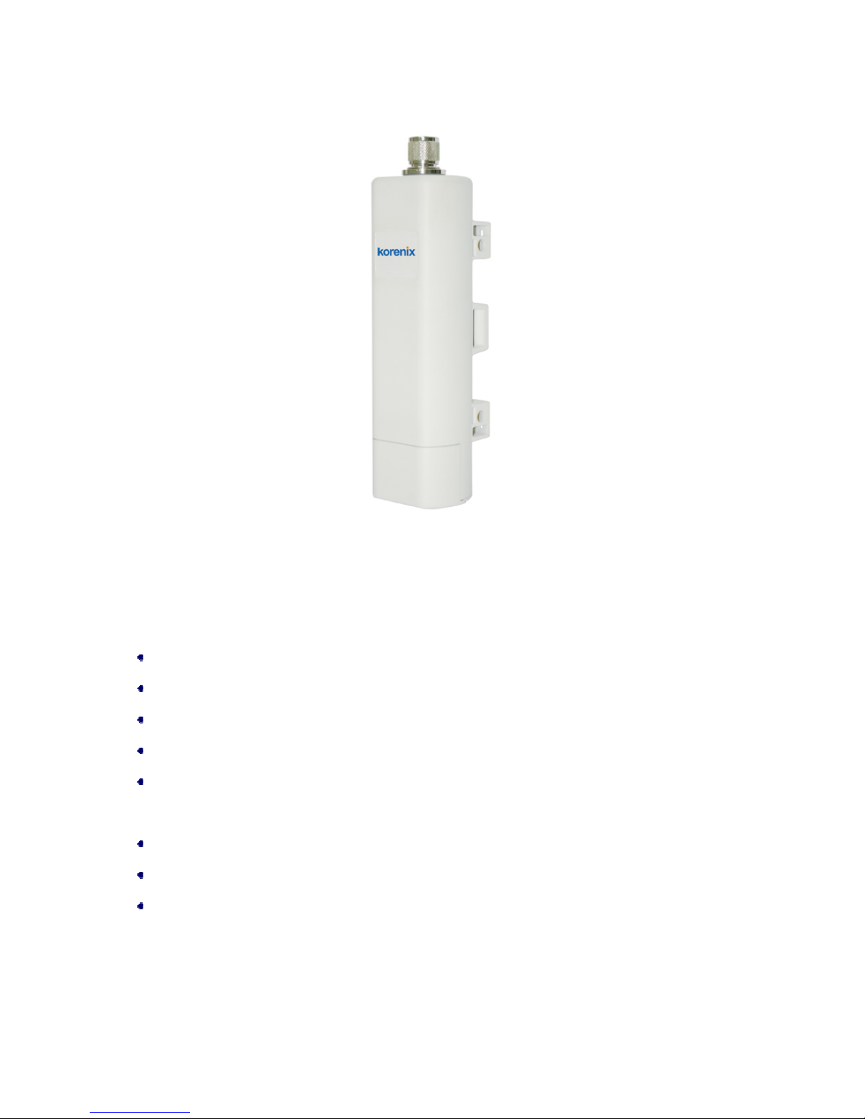
Figure 1 JetWave 2450
Key Features
Compliant with IEEE 802.11b/g and IEEE 802.11n draft 2.0 as well
Support Power over Ethernet (PoE)
IP65 waterproof housing endures almost any harsh environments
Dual operating modes including AP and Wireless Client
Support 64/128-bit WEP and 802.1X, WPA, WPA2, WPA&WPA2,WPA-PSK, WPA2-PSK, and
WP A-PSK&WPA2-PSK etc
Support WMM and Quality of service (QoS) for enhanced performance
Advanced management tools like SNMP
User-friendly Web and SNMP-based management interface
Page 13
Chapter 1 Introduction Page 3
T ypical Application
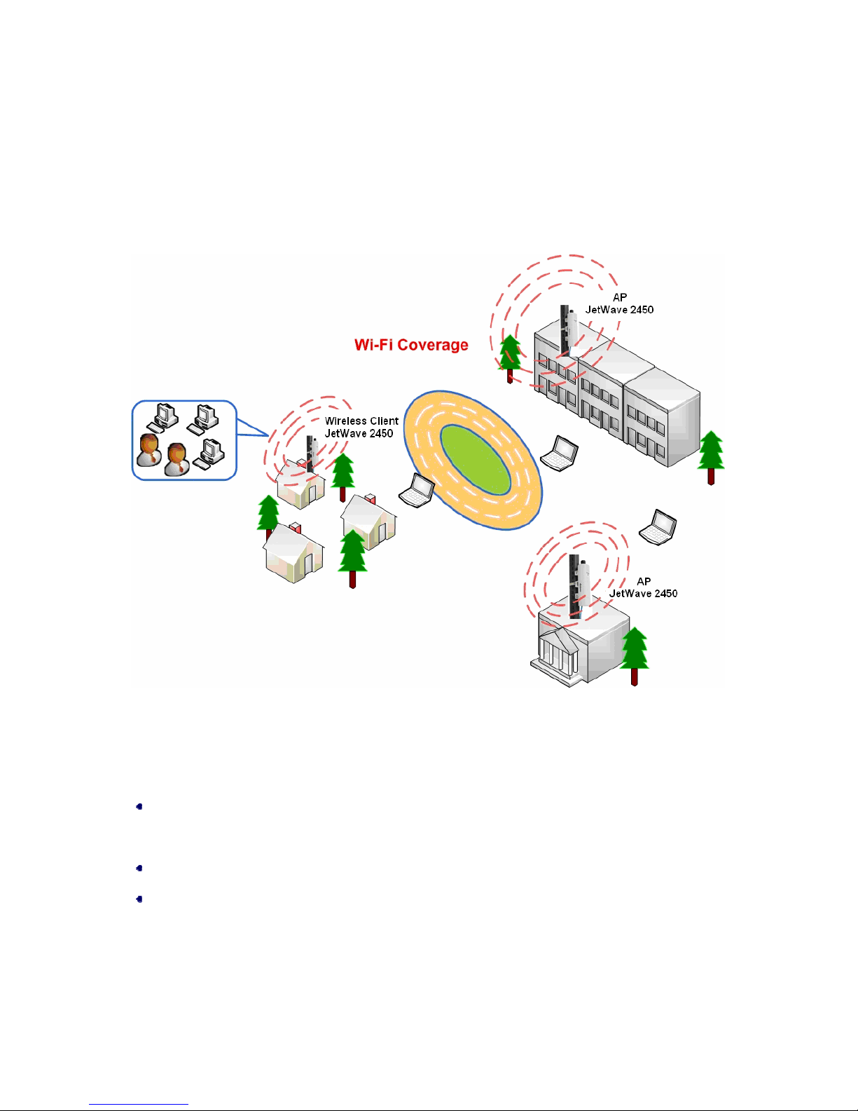
This section describes the typical applications of JetWave 2450. By default, it is set to AP mode which
allows it to establish a wireless coverage; besides, it is also able to join any available wireless network
under wireless client mode. The JetWave 2450 is able to deliver stable and efficient broadband
connectivity for various applications.
Figure 2 Typical Application
Besides, the JetWave 2450 can also be applied into the following environments:
Cost-effectively provide long distance backhaul for remote areas (e.g. village, oil well, island,
mountain and etc.)
Establish local backhaul for campus, farm and factory
Provide and access for video streaming or surveillance for industrial and mining enterprises
Page 14

Chapter 2 Hardware Installation Page 4
Chapter 2 Hardware Installation
This chapter describes safety precautions and product information you have to kno w and check before
installing JetWave 2450.
Preparation before Installation
Professional Installation Required
1. Please seek assistance from a professional installer who is well trained in the RF installation and
knowledgeable in the local regulations.
2. The JetWave 2450 is distributed through distributors and system installers with professional
technicians and will not be sold directly through retail stores.
Safety Precautions
1. To keep you safe and install the hardware properly, please read and follow these safety
precautions.
2. If you are installing JetWave 2450 for the first time, for your safety as well as others’, please
seek assistance from a professional installer who has received safety training on the hazards
involved.
3. Keep safety as well as performance in mind when selecting your installation site, especially
where there are electric power and phone lines.
4. When installing JetWave 2450, please note the following things:
♦ Do not use a metal ladder;
♦ Do not work on a wet or windy day;
♦ Wear shoes with rubber soles and heels, rubber gloves, long sleeved shirt or jacket.
5. When the system is operational, avoid standing directly in front of it. Strong RF fields are present
when the transmitter is on.
Page 15

Chapter 2 Hardware Installation Page 5
Installation Precautions
To keep the JetWave 2450 well while you are installing it, please read and follow these installation
precautions.
1. Users MUST use a proper and well-installed surge arrestor and grounding kit with Jet W ave 24 50;
otherwise, a random lightening could easily cause fatal damage to JetWave 2450. EMD
(Lightning) DAMAGE IS NOT COVERED UNDER WARRNTY.
2. Users MUST use the “Power cord & PoE Injector” shipped in the box with the JetWave 2450.
Use of other options will cause damage to the JetWave 2450.
3. Users MUST power off the JetWave 2450 first before connecting the external antenna to it;
otherwise, damage might be caused to the JetWave 2450 itself.
Product Package
The product package you have received should contain the following items. If any of them are not
included or damaged, please contact your local vendor for support.
JetWave 2450 ×1
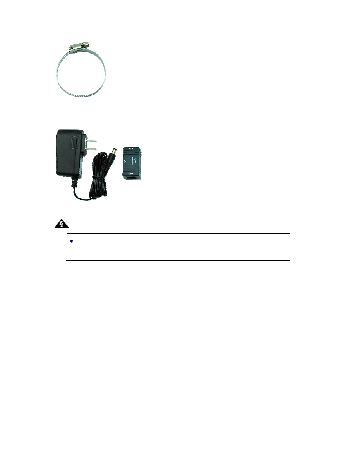
Pole Mounting Ring ×1
Power Cord & PoE Injector ×1
Quick Installation Guide ×1
Product CD ×1
Note:
Product CD contains Quick Installation Guide and User Manual!
Page 16
Chapter 2 Hardware Installation Page 6
Pole Mounting Ring
Power Cord & PoE Injector
Warning:
Users MUST use the “Power cord & PoE Injector” shipped in the box with the JetWave
2450. Use of other options will cause damage to the JetWave 2450.
Page 17
Chapter 2 Hardware Installation Page 7
Hardware Installation
Connect up
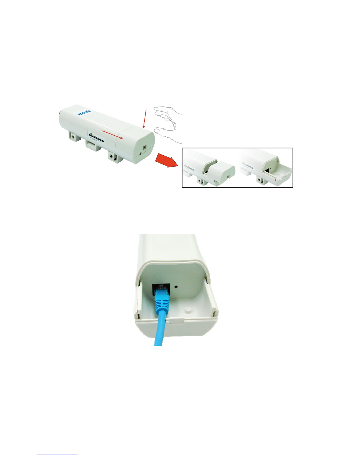
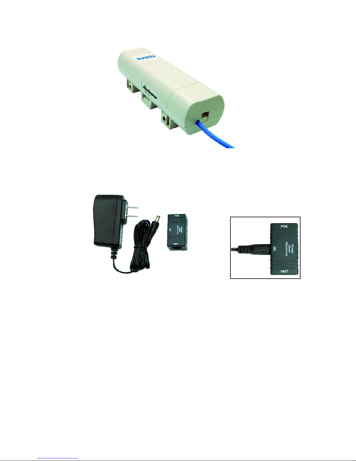
1. The bottom of the JetWave 2450 is a movable cover. Grab the cover and pull it back harder to
take it out as the figure shown below.
Figure 3 Move the Cover
2. Plug a standard Ethernet cable into the RJ45 port.
Figure 4 Cable Connection
Page 18
Chapter 2 Hardware Installation Page 8
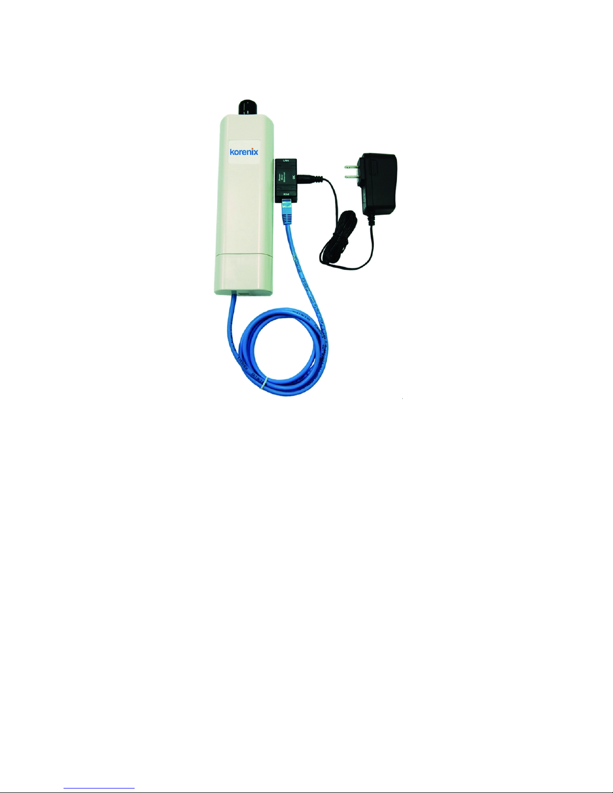
3. Slide the cover back to seal the bottom of the JetWave 2450.
Figure 5 Seal the Bottom
4. Plug the power cord into the DC port of the PoE injector as the following right picture shows.
Figure 6 Connect to PoE Injector
Page 19
Chapter 2 Hardware Installation Page 9
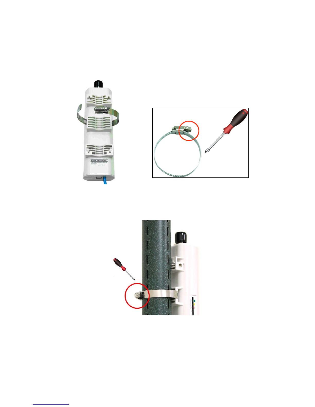
5. Plug the other side of the Ethernet cable as shown in Step 3 into the PoE port of the PoE injector
and get the complete set ready.
Figure 7 Complete Set
Page 20
Chapter 2 Hardware Installation Page 10
Pole Mounting
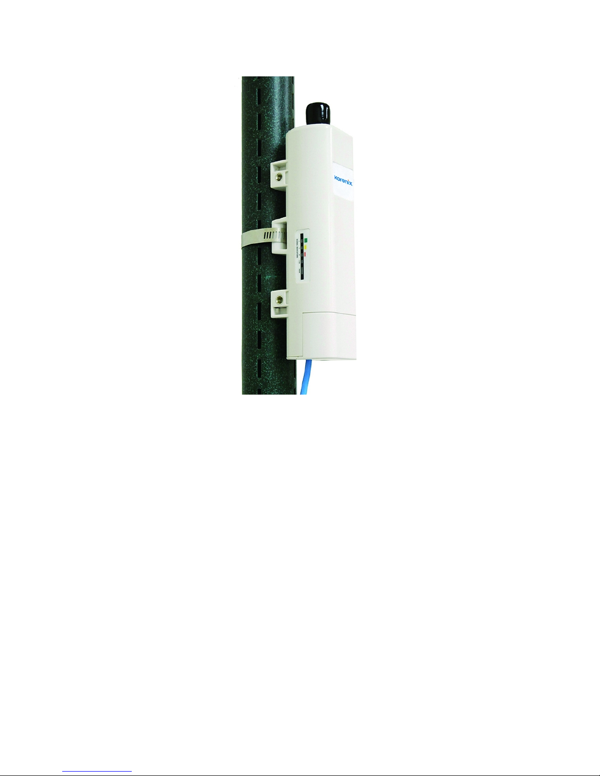
1. Turn the JetWave 2450 over. Put the pole mounting ring through the middle hole of it. Note that
you should unlock the pole mounting ring with a screw driver before putting it through JetWave
2450 as the following right picture shows.
Figure 8 Pole Mounting – Step 1
2. Mount JetWa v e 2450 steadily to the pole by locking the pole mounting ring tightly.
Figure 9 Pole Mounting – Step 2
Page 21
Chapter 2 Hardware Installation Page 11
3. Now you have completed the hardware installation of JetWave 2450.
Figure 10 Pole Mounting – Step 3
Page 22
Chapter 2 Hardware Installation Page 12
Using the External Antenna
If you prefer to use the external antenna with N-type connector for your application instead of the
built-in directional antenna, please follow the steps below.
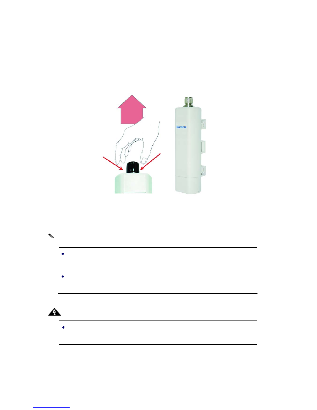
1. Grab the black rubber on the top of JetWave 2450, and slightly pull it up. The metal N-type
connector will appear.
Figure 11 Move the Rubber
2. Connect your antenna with the N-type connector on the top of JetWave 2450.
If you are going to use an external antenna on JetWave 2450, get some cable in
advance.
Be aware of the force you use while connecting to the N-type connector, inappropriate
force may damage the N-type connector!
Users MUST power the JetWave 2450 off first before connecting the external antenna
to it; otherwise, damage might be caused to the JetWave 2450 itself.
Warning:
Note:
Page 23

Chapter 3 Basic Settings Page 13
Chapter 3 Basic Settings
Factory Default Settings
We’ll elaborate the JetWave 2450 factory default settings. You can re-acquire these parameters by
default. If necessary, please refer to the “Restore Factory Default Settings
”.
T able 1 JetWave 2450 Factory Default Settings
Features Factory Default Settings
Username admin
Password password
Wireless Device Name apXXXXXX (X represents the last 6
digits of Ethernet MAC address)
Operating Mode AP
Data Rate Auto
IP Address 192.168.1.1
Subnet Mask 255.255.255.0
Gateway 0.0.0.0
Primary DNS Server 0.0.0.0
LAN
Secondary DNS Server 0.0.0.0
Spanning Tree Enable
802.11 Mode 802.11b/g/n
Channel Number 6
SSID Wireless
Broadcast SSID Enable
HT Protect Disable
Data Rate Auto
Output Power 100% (Full)
Channel Mode 20MHz
WMM Enabled
RTS Threshold (byte) 2346
Fragmentation Length (byte) 2346
Beacon Interval 100
DTIM Interval 1
Space in Meter 0
Flow Control by AP Disable
Security Open System
Encryption None
Page 24
Chapter 3 Basic Settings Page 14
Wireless Separation Disable
Access Control Disable
Enable/Disable Enable
Read Community Name Public
Write Community Name Private
SNMP
IP Address 0.0.0.0
System Requirements
Before configuration, please make sure your system meets the following requirements:
A computer coupled with 10/ 100 Base-TX adapter;
Configure the computer with a static IP address of 192.168.1.x, as the default IP address of
JetWave 2450 is 192.168.1.1. (X cannot be 0, 1, nor 255);
A Web browser on PC for configuration such as Microsoft Internet Explorer 6.0 or above,
Netscape or Firefox.
How to Login the Web-based Interface
The JetWave 2450 provides you with user-friendly Web-based management tool.
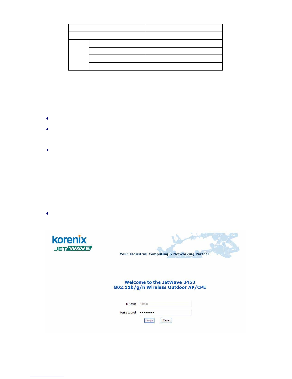
Open Web browser and enter the IP address (Default: 192.168.1.1) of JetWave 2450 into the
address field. You will see the login page as below.
Figure 12 Login Page
Page 25
Chapter 3 Basic Settings Page 15
Enter the username (Default: admin) and password (Default: password) respectively and click
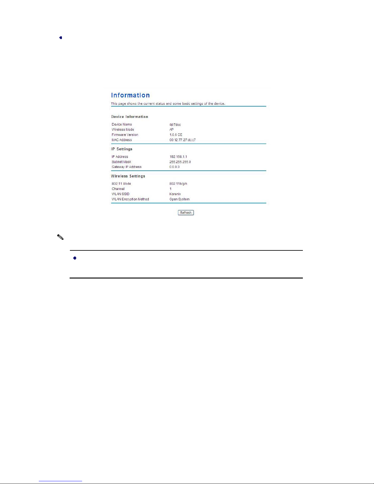
“Login” to login the main page of JetWave 2450. You can see the basic information of JetWave
2450. This management interface provides five main options, which are S tatus, System, Wirele ss,
Management and Tools.
Figure 13 Main Page
The username and password are case-sensitive, and the password should be no
more than 19 characters!
Note:
Page 26
Chapter 3 Basic Settings Page 16
Basic System Settings
For users who use the JetWave 2450 for the first time, it is recommended that you begin configuration
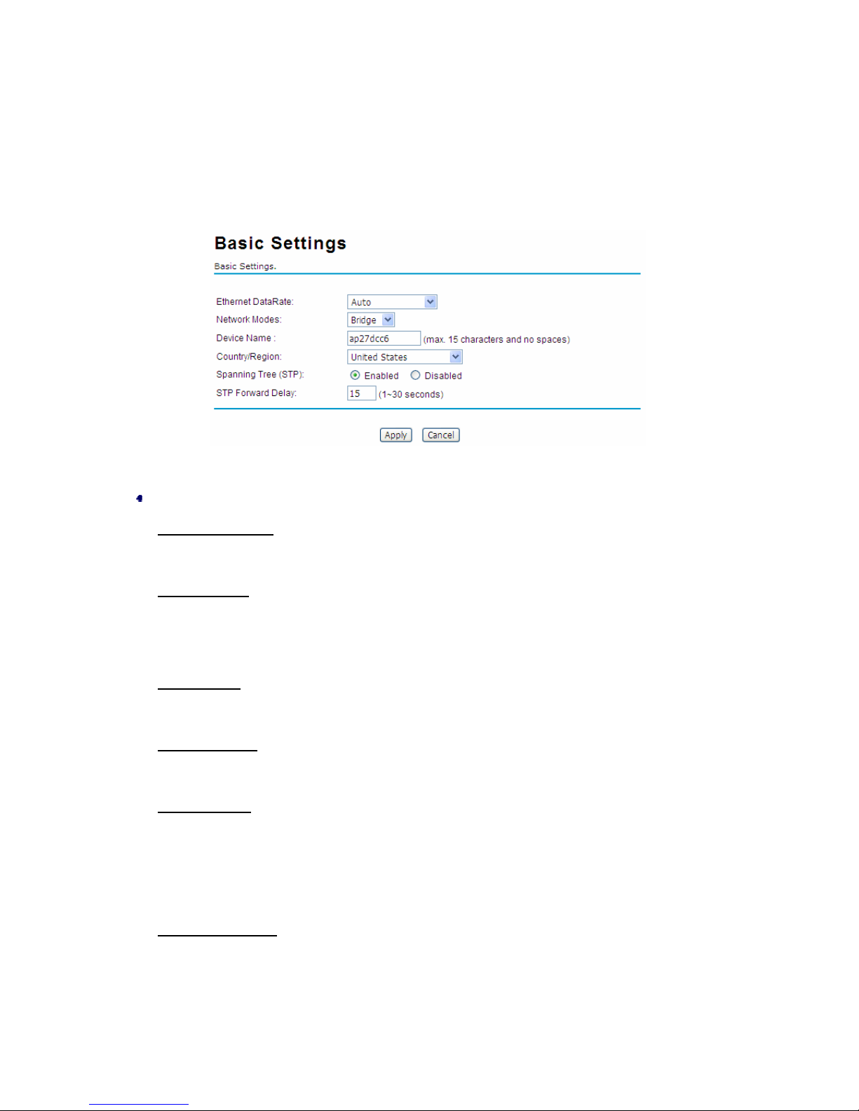
from “Basic Settings” in “System” shown below:
Figure 14 Basic System Settings
Basic Settings
Ethernet DataRate
: Adjust the data rate of Ethernet connection, including 10/100M full-duplex,
half-duplex and Auto.
Network Mode
: Specify the network mode, including Bridge and Router. It is easy to configure
parameters in Bridge Mode; however , users must pay extra attention to the way they configure the
device when it is set to Router Mode. For details, please refer to “IP Settings (Router)”.
Device Name
: Specify the device name, which is composed of no more than 15 characters with
(0-9), (A-Z), (a-z) or (-).
Country Region
: The availability of some specific channels and/or operational frequency bands
is country dependent.
Spanning Tree
: Spanning Tree Protocol (STP) is a link management protocol for AP which
provides path redundancy while preventing loops in a network. STP allows only one active path
at a time between the access points but establish the redundant link as a backup if the initial link
fails.
STP Forward delay
: Enter a value between 1 and 30 seconds. This value is the time that a port
waits before changing from Spanning Tree Protocol learning and listening states to forwarding
state.
Page 27
Chapter 3 Basic Settings Page 17
IP Settings (Bridge)
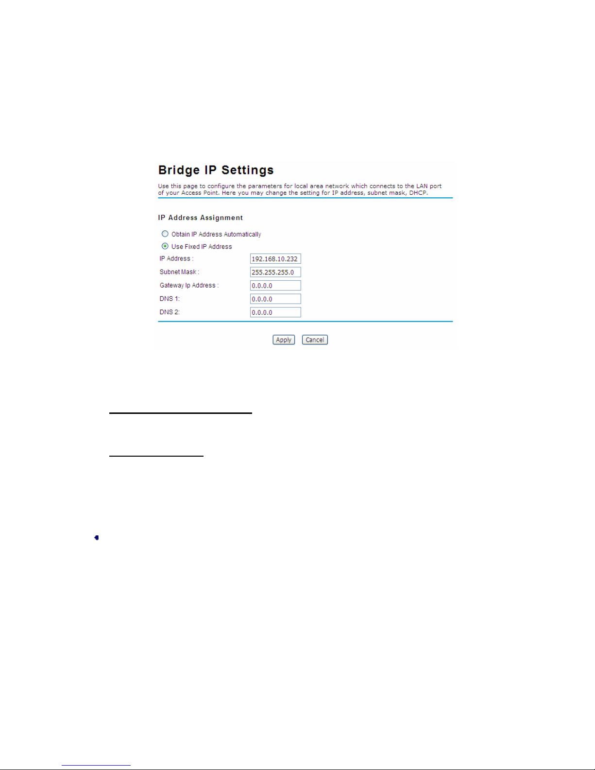
This is available only under Bridge network mode. Open “IP Settings (Bridge)” in “System” as
below to configure the parameters for LAN which connects to the LAN port of JetWave 2450. In
this page, users may change the settings for IP Address, Subnet Mask, and DHCP Server.
Figure 15 IP Settings (Bridge)
Obtain IP Address Automatically
: If a DHCP server exists in your network, you can check this
option, thus the JetWave 2450 is able to obtain IP settings automatically from that DHCP serve r.
Use Fixed IP Address
: Check this option. You have to specify a static IP address, subnet mask,
default gateway and DNS server for JetWave 2450 manually. Make sure the specified IP address
is unique on your network in order to prevent IP conflict.
IP Settings (Router)
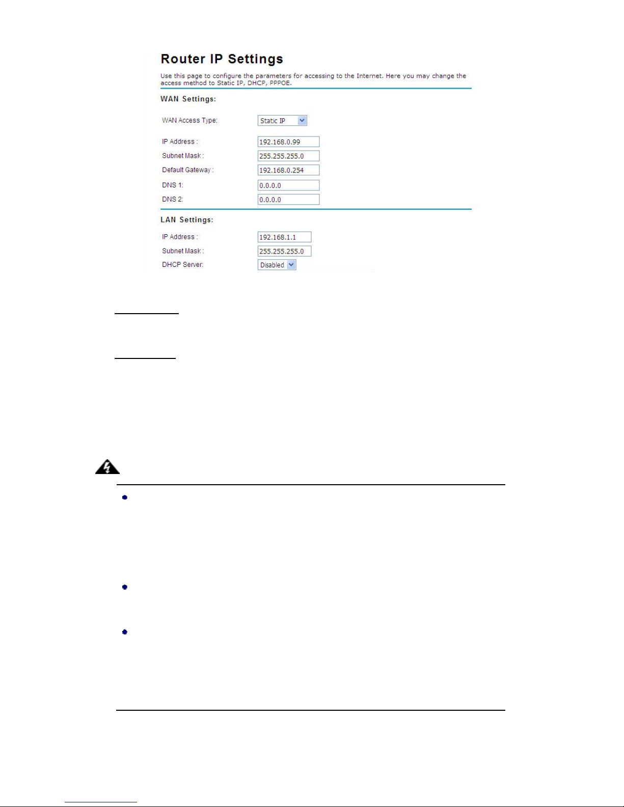
This is available only under Router mode. Open “IP Settings (Router)” in “System” as below to
configure the parameters of JetWave 2 450 for accessing the Internet.
Page 28
Chapter 3 Basic Settings Page 18
Figure 16 IP Settings (Router)
WAN Settings
: Specify the Internet access method to Static IP, DHCP or PPPOE. Users must
enter WAN IP Address, Subnet Mask, Gateway settings provided by your ISPs.
LAN Settings
: When DHCP Server is disabled, users can specify IP address and subnet mask
for JetWave 2450 manually. Make sure the specified IP address is unique on your network in
order to prevent IP conflict. When DHCP Server is enabled, users may specify DHCP IP Address
Range, DHCP Subnet Mask, DHCP Gateway and Lease Time (15-44640 minutes).
Warning:
In AP mode, JetWave 2450 must establish connection with another wireless device
before it is set to Router mode. In Router mode, it is impossible for users to access
device via wired port, for WAN is on wired port and LAN is on wirele ss port. Use rs can
access device through the wireless device connected with JetWave 2450.
In CPE mode, users can access JetWave 2450 via its wired port, for WAN is on
wireless port and LAN is on wired port when device is set to Router mode.
Bridge mode and AP Repeater mode are similar to AP mode when device is set to
Router mode; WAN is on wired p ort and LAN is on wi reless port. Thus u sers must also
connect JetWave 2450 with another wireless device before it is set to Router mode
and access JetWave 2450 via the connected wireless device.
Page 29
Chapter 3 Basic Settings Page 19
RADIUS Settings
RADIUS (Remote Authentication Dial-In User Service) is a server for remote user authentication and
accounting; playing a central role in the network in providing the capabilities of authenticating,
authorizing, accounting, auditing, alarming and etc. It allows an organization to maintain user profiles
in a central database that all remote servers can share.
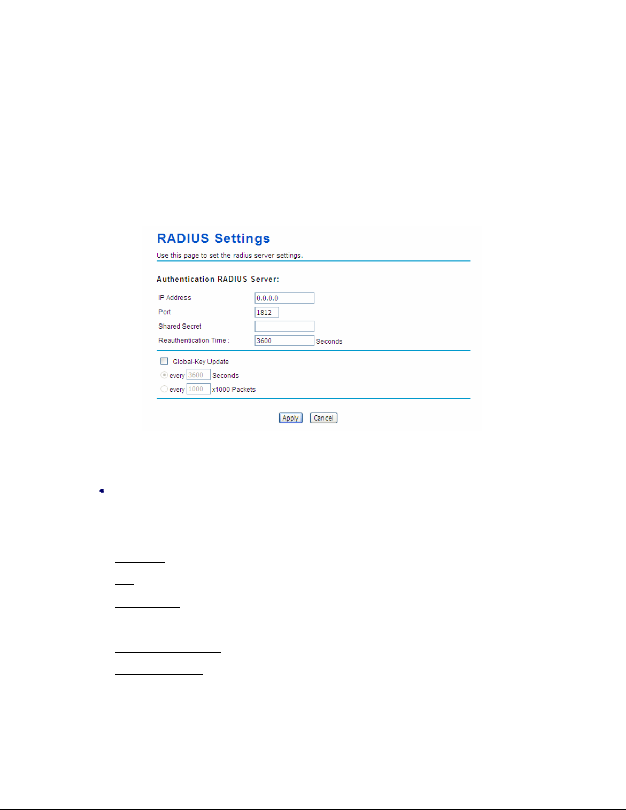
Open “RADIUS Settings” in “System” to make RADIUS configuration.
Figure 17 RADIUS Settings
Authentication RADIUS Server
This is for RADIUS authentication. It can communicate with RA DIUS through IP Addre ss, Port and
Shared Secret.
IP Address
: Enter the IP address of the Radius Server;
Port
: Enter the port number of the Radius Server;
Shared Secret
: This secret, which is composed of no more than 31 characters, is shared by the
JetWave 2450 and RADIUS during authentication.
Re-authentication Time
: Set the time interval between two authentications.
Global-Key Update
: Check this option and specify the time interval between two global-key
updates.
Page 30
Chapter 3 Basic Settings Page 20
Time Settings
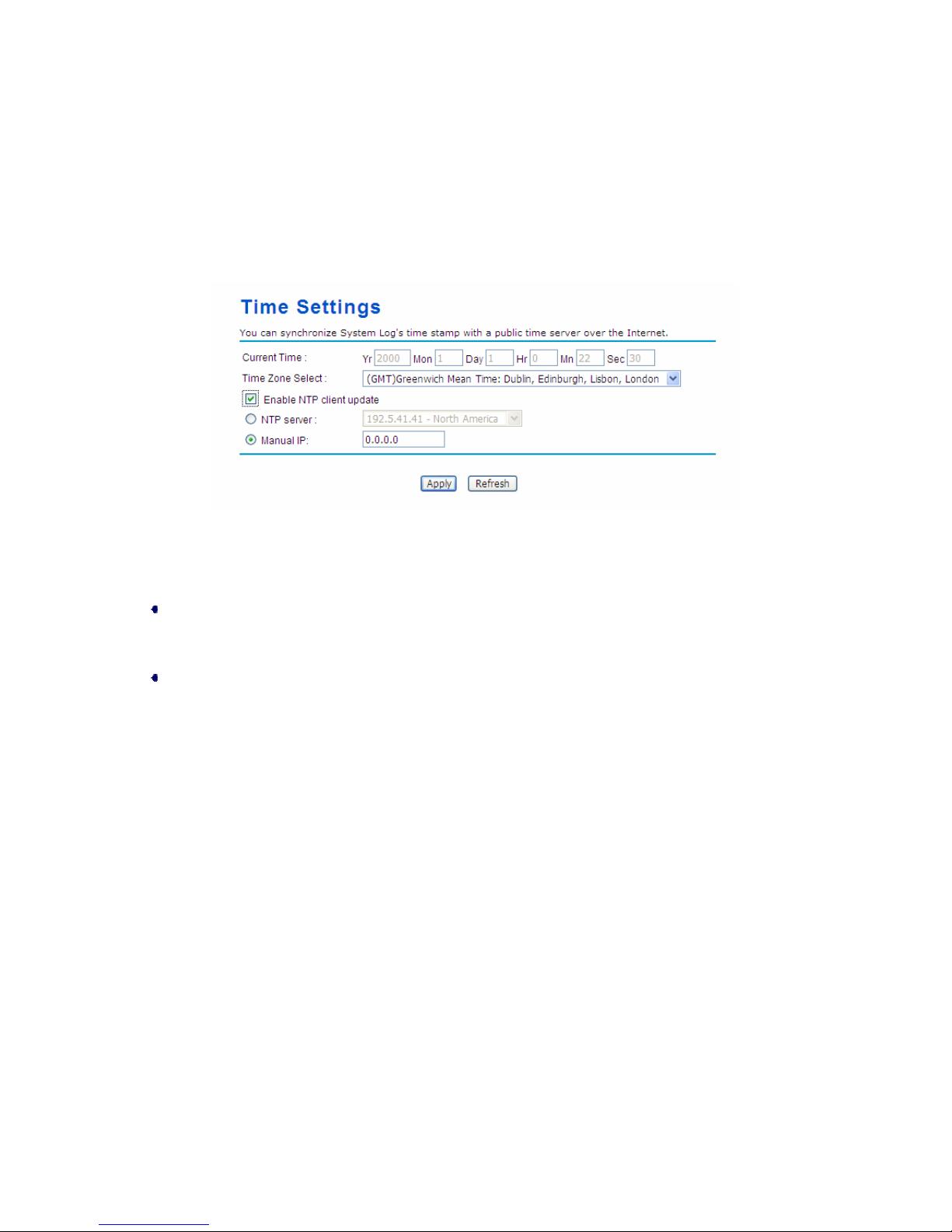
Compliant with NTP, the JetWave 2450 is capable of keeping its time in complete accord with the
Internet time. Make configuration in “Time Settings” from “System”. To use this feature, check
“Enable NTP Client Update” in advance.
Figure 18 Time Settings
Time Zone Select
Select the time zone from the dropdown list.
Time Server
Select the time server from the “NTP Server” dropdown list or manually input the IP address of
available time server into “Manual IP”.
Hit “Apply” to save settings.
Firewall Settings
The firewall is a system or group of systems that enforce an access control policy between two
networks. It may also be defined as a mechanism used to protect a trusted network from an un-trusted
network. JetWave 2450 has capabilities of Source IP Filtering, Destination IP Filtering, Source Port
Filtering, Destination Port Filtering, Port Forwarding and DMZ. This is available only under Router
Mode.
Page 31
Chapter 3 Basic Settings Page 21
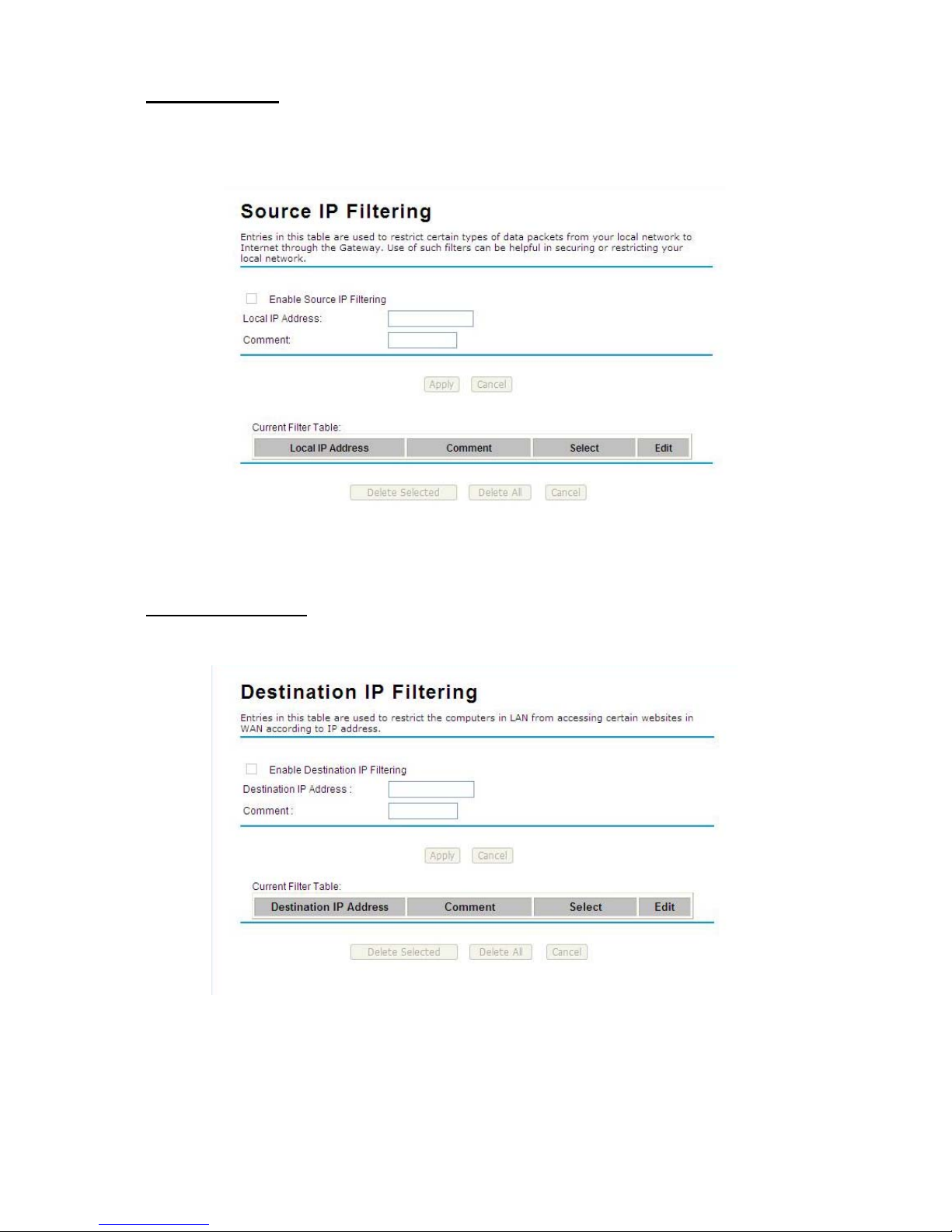
Source IP Filtering: The source IP filtering gives users the ability to restrict certain types of data
packets from your local network to Internet through JetWave 2450. Use of such filters can be helpful in
securing or restricting your local netwo rk.
Figure 19 Source IP Filtering
Destination IP Filtering
: The destination IP filtering gives you the ability to restrict the computers in
LAN from accessing certain websites in WAN according to specified IP addresses.
Figure 20 Destination IP Filtering
Page 32
Chapter 3 Basic Settings Page 22
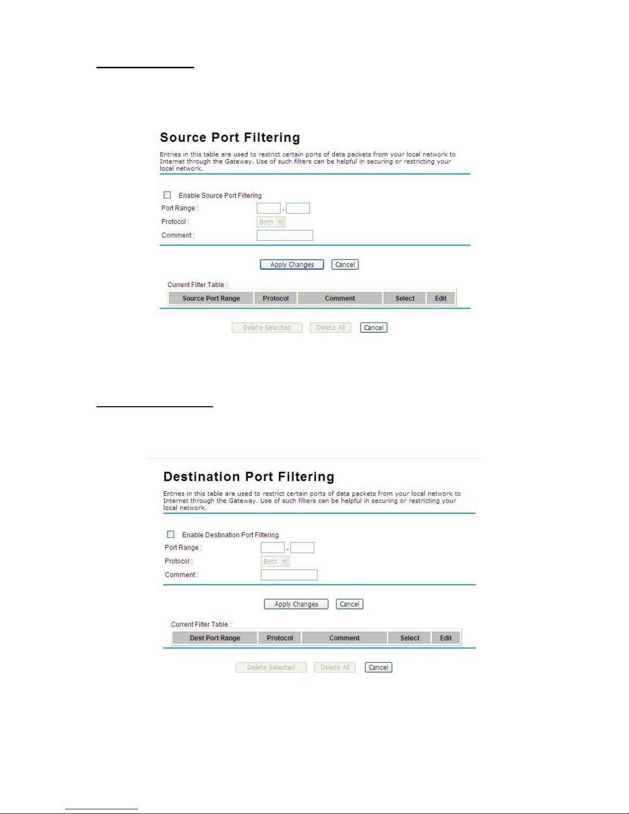
Source Port Filtering: The source port filtering enable you to restrict certain ports of data packets
from your local network to Internet through JetWave 2450. Use of such filters can be helpful in
securing or restricting your local netwo rk.
Figure 21 Source Port Filtering
Destination Port Filtering
: The destination port filtering enables you to restrict certain ports of data
packets from your local network to Internet through JetWave 2450. Use of such filters can be helpful in
securing or restricting your local netwo rk.
Figure 22 Destination Port Filtering
Page 33
Chapter 3 Basic Settings Page 23
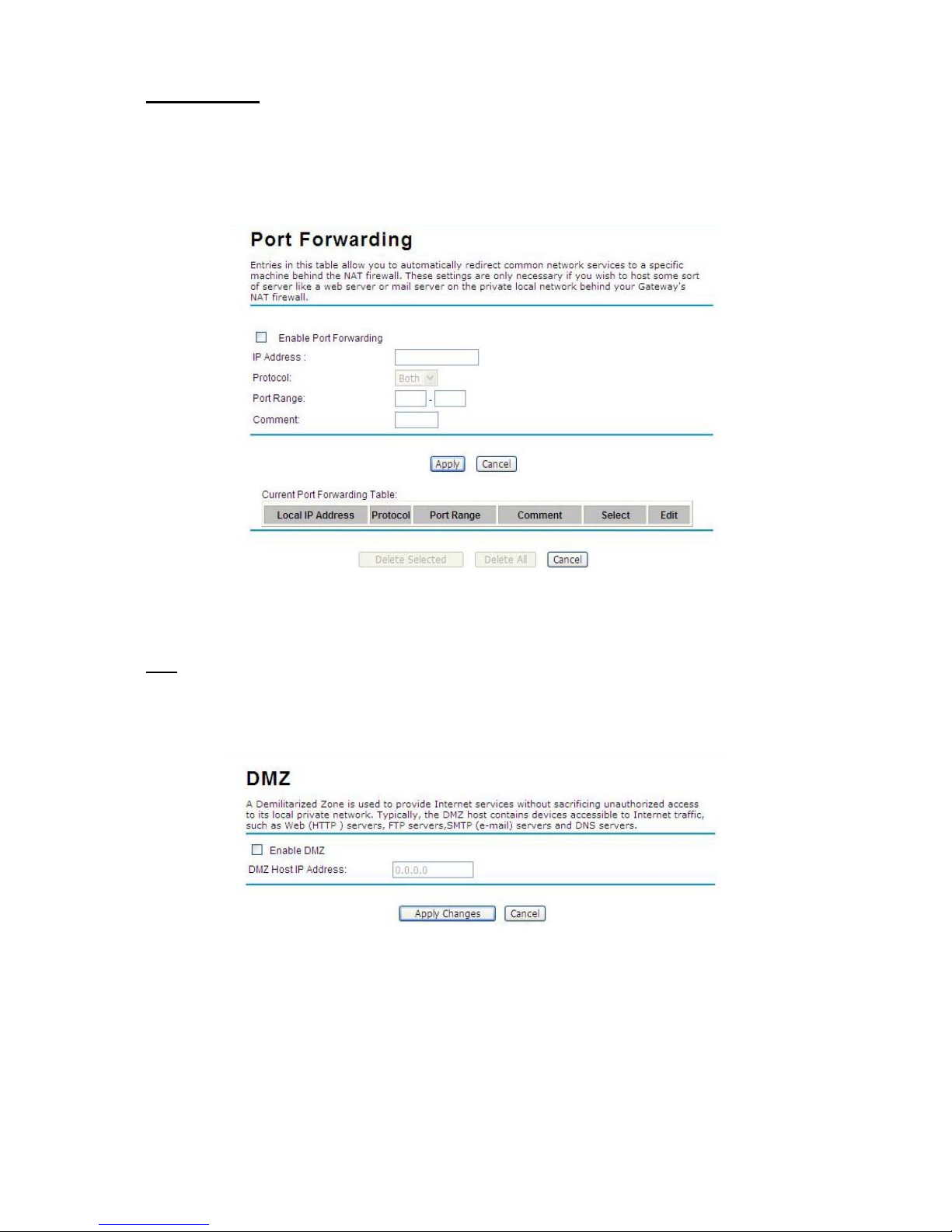
Port Forwarding: The port forwarding allows you to automatically redirect common network services
to a specific machine behind the NAT firewall. These settings are only necessary if you wish to host
some sort of server like a web server or mail server on the private local network behind JetWave
2450’s NAT firewall.
Figure 23 Port Forwarding
DMZ
: A Demilitarized Zone is used to provide Internet services without sacrificing unauthorized access
to its local private network. Typically, the DMZ host contains devices accessible to the Internet traffic,
such as Web (HTTP) servers, FTP servers, SMTP (e-mail) servers and DNS servers.
Figure 24 DMZ
Page 34
Chapter 3 Basic Settings Page 24
Basic Wireless Settings
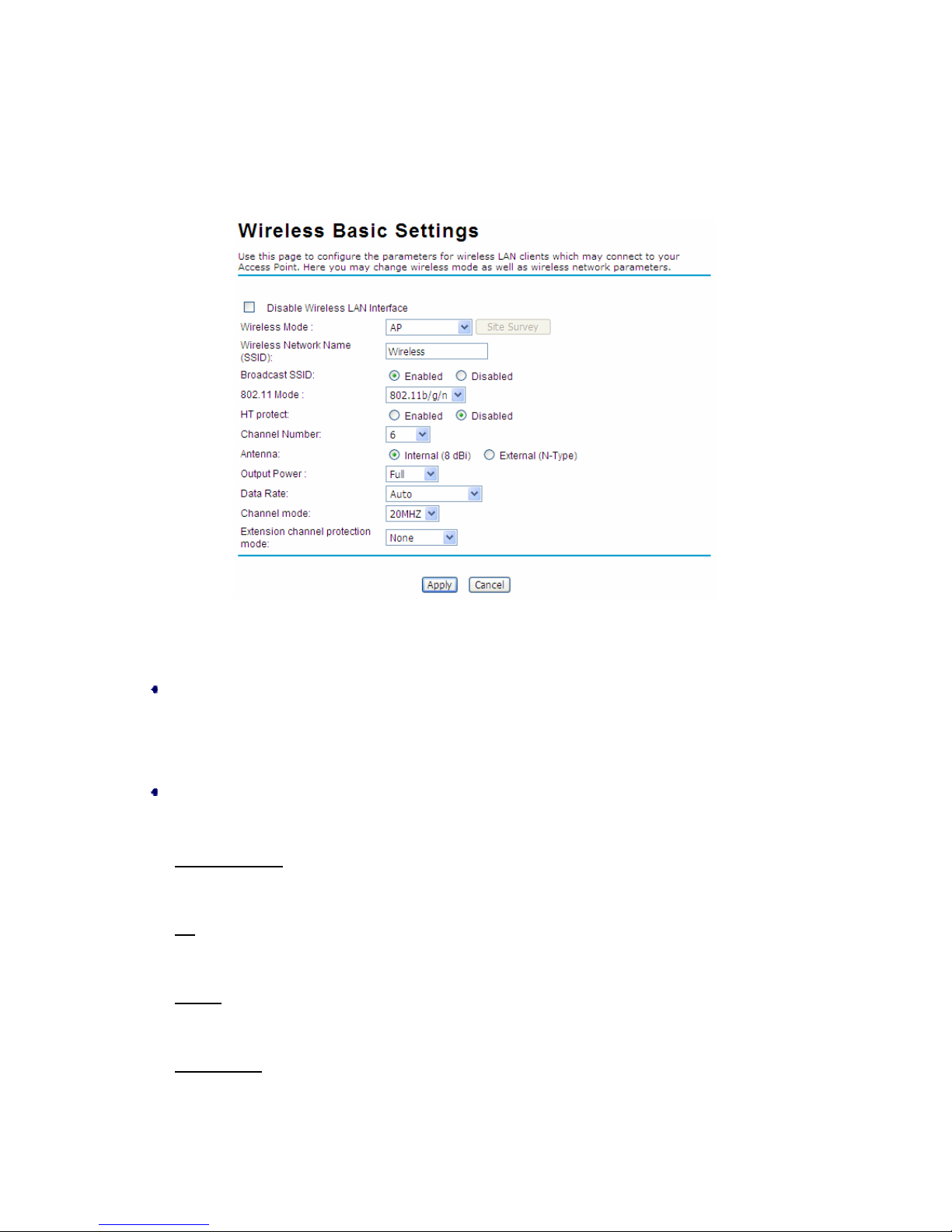
Open “Basic Settings” in “Wireless” as below to make basic wireless configuration.
Figure 25 Basic Wireless Settings
Disable Wireless LAN Interface
Check this option to disable WLAN interface, then the wireless module of JetWave 2450 will stop
working and no wireless device can connect to it.
Wireless Mode
Four operating modes are available on JetWave 2450.
Wireless Client
: The JetWave 2450 is able to connect to the AP and thus join the wireless
network around it.
AP
: The JetWave 2450 establishes a wireless coverage and receives connectivity from other
wireless devices.
Bridge
: The JetWave 2450 establishes wireless connectivity with other APs by key-in remote
MAC address .If necessary, please refer to the “WDS Setting”.
AP Repeater
: The JetWave 2450 servers as AP and Bridge at the same time. In other words, the
JetWave 2450 can provide connectivity services for CPEs unde r WDS mode.
Page 35

Chapter 3 Basic Settings Page 25
Wireless Network Name (SSID)
This wireless network name is shared among all associated devices in your wireless network.
Keep it identical on all those devices. Note that the SSID is case-sensitive and can not exceed 32
characters.
Broadcast SSID
Under AP mode, hiding network name is necessary when you are in a wireless environment that
may have potential risk. By disabling broadcast SSID, the STA can not scan and find JetWave
2450, so that malicious attack by some illegal STA could be avoided.
802.11 Mode
The JetWave 2450 can communicate with wireless devices of 802.11b/g or 802.11b/g/n. You can
also select Auto and make it work under an appropriate wireless mode automatically.
HT Protect
Enable HT (High Throughput) protect to ensure HT transmission with MAC mechanism. Under
802.1 1n mode, wirel ess client ca n be divided into HT STA and Non-HT STA, among which the one
with HT protect enabled gets higher throughput.
Channel Number
Channel varies much as the available band differs from country to country. Select a proper
operating channel in the drop-down list according to your situation.
Antenna
By default, JetWave 2450 uses its built-in antenna for directional transmission; however, if you
prefer to use an external antenna for your case-dependent applications, you can switch from
“Internal (8 dBi)” to”External (N-Type)”.
Note:
You a re able to choose “External (N-Type)” only when you have well done installing the
external antenna; otherwise, it might hurt JetWave 2450 itself.
Output Power
Specify the signal transmission power. The higher the output power is, the wider the signal can
cover, but the power consumption will be greater accordingly. Usually “Full” is preferred.
Page 36
Chapter 3 Basic Settings Page 26
Data Rate
Usually “Auto” is preferred. Under this rate, the JetWave 2450 will automatically select the highest
available rate to transmit. In some cases, however, like where there is no great demand for speed,
you can have a relatively-low transmit rate for compromise of a long distance.
Channel Mode
Two levels are available: 20MHz and 40MHz. The latter one can enhance the data rate more
effectively, but takes more bandwidth, thus cause potential interference.
Extension Channel Protection Mode
This is to avoid conflict with other wireless network and boost the ability of your device to catch all
802.11g transmissions. However, it may decrease wireless network performance. Compared to
CTS-Self; the transmission amount of CTS-RTS is much lower.
Enable MAC Clone
Available only under wireless client mode, it hides the MAC address of the AP while displays the
one of associated wireless client or the MAC address designated manually.
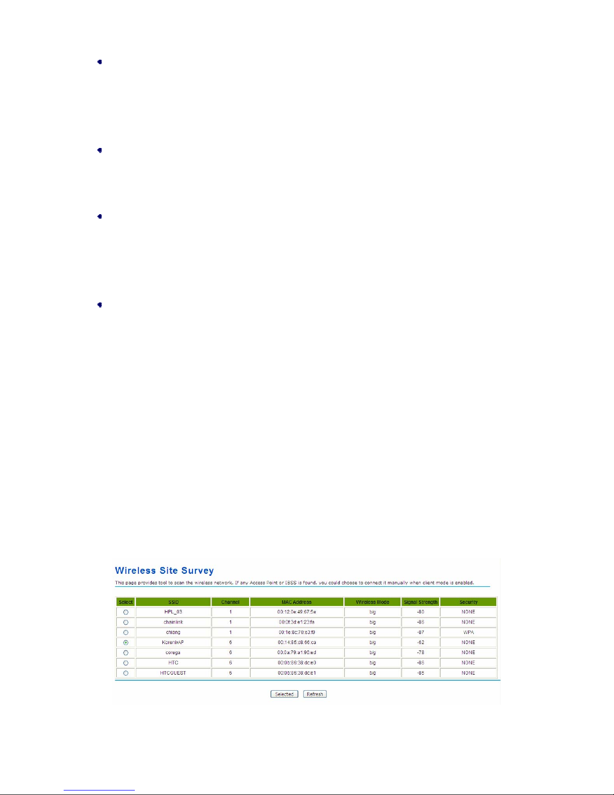
Site Survey
Under wireless client mode, the JetWave 2450 is able to perform site survey, through which,
information on the available access points will be detected.
Open “Basic Settings” in “Wireless”, by clicking the “Site Survey” button beside “Wireless Mode”
option, the wireless site survey window will popup with a list of available wireless networks around.
Select the AP you woul d like to conne ct and clic k “Selected” to establish connection. The wireless site
survey window can also be viewed by opening the “Site Survey” page in “Tools”.
Figure 26 Site Survey
Page 37
Chapter 4 Advanced Settings Page 27
Chapter 4 Advanced Settings
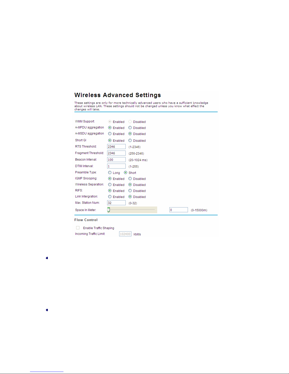
Advanced Wireless Settings
Open “Advanced Settings” in “Wireless” to make advanced wireless settings.
©
Figure 27 Advanced Wireless Settings
WMM Support
WMM (Wi-Fi Multimedia) is a subset of 802.11e. It allows wireless communication to define a
priority limit on the basis of data type under AP mode only, thus those time-sensitive data, like
video/audio data, may own a higher priority than common one. To enable WMM, the wireless
client should support it.
A-MPDU/A-MSDU Aggregation
The data rate of your AP except wireless client mode could be enhanced greatly with this option
enabled; however, if your wireless clients don’t support A-MPDU/A-MSDU aggregation, it is
recommended not to enable it.
Page 38

Chapter 4 Advanced Settings Page 28
Short GI
Under 802.1 1 n mode, enable it to obt ain better data rate if there is no negative co mpatibility issue.
RTS Threshold
The JetWave 2450 sends RTS (Request to Send) frames to certain receiving station and
negotiates the sending of a data frame. After receiving an RTS, that STA responds with a CTS
(Clear to Send) frame to acknowledge the right to start transmission. The setting range is 0 to
2346 in byte.
Fragmentation Length
Specify the maximum size in byte for a packet before data is fragmented into multiple packets.
Setting it too low may result in poor network performance. Leave it at its default of 2346 is
recommended.
Beacon Interval
Specify the frequency interval to broadcast packets. Enter a value between 20 and 1024.
DTIM Interval
DTIM, which stands for Delivery Traffic Indication Message, is contained in the data packets. It is
for enhancing the wireless transmission ef ficiency. The default is set to 1. Enter a value between 1
and 255.
Preamble Type
It defines some details on the 802.11 physical layer. “Long” and “Short” are available.
IGMP Snooping
IGMP snooping is the process of listening to IGMP network traffic. By enabling IGMP snooping,
the AP will listen to IGMP membership reports, queries and leave messages to identify the ports
that are members of multicast groups. Multicast traffic will only be forwarded to ports identified as
members of the specific multicast group or groups.
Wireless Separation
Wireless separation is an ideal way to enhance the security of network transmission. Under the
mode except wirless client mode, enable “Wireless Separation” can prevent the communication
among associated wireless clients.
RIFS
RIFS (Reduced Interframe Spacing) is a means of reducing overhead and thereby increasing
network efficiency.
Page 39

Chapter 4 Advanced Settings Page 29
Link Integration
Available under AP/Bridge/AP repeater mode, it monitors the connection on the Ethernet port by
checking “Enabled”. It can inform the associating wireless clients as soon as the disconnection
occurs.
Max. Station Num
Available only under AP mode, it defines the maximum amount of wireless clients allowed to be
connected.
Space in Meter/ACK Timeout
To decrease the chances of data retransmission at long distance, the JetWave 2450 can
automatically adjust proper ACK timeout value by specifying distance of the two nodes.
Flow Control
It allows the administrator to specify the incoming and outgoing traffic limit by checking “Enable
Traffic Shaping”. This is only available in Router mode.
We strongly recommended you leave most advanced settings at their defaults except
“Distance in Meters” adjusted the parameter for real dist an ce; any modificatio n on them
may negatively impact the performance of your wireless network.
Note:
Page 40
Chapter 4 Advanced Settings Page 30
Wireless Security Settings
To prevent unauthorized radios from accessing data transmitting over the connectivity, the JetWave
2450 provides you with rock solid security settings.
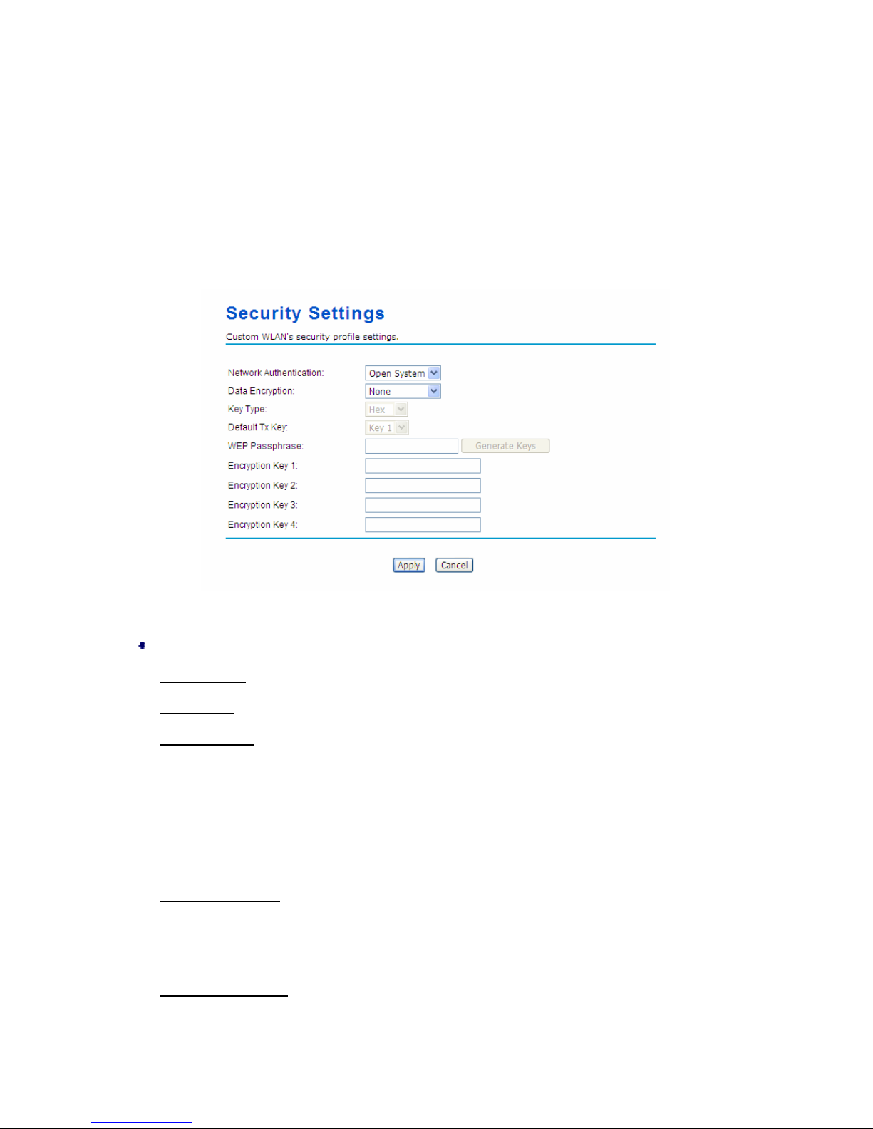
Security Settings
Open “Security Settings” in “Wireless” as below:
Figure 28 Security Settings
Network Authentication
Open System
: It allows any device to join the network without performing any security check.
Shared Key
: Data encryption and key are required for wireless authentication.
Legacy 802.1x
: As an IEEE standard for port-based Network Access Control, it provides the
rights to access the wireless network and wired Ethernet. With User and PC identity, centralized
authentication as well as dynamic key management, it controls the security risk of wireless
network to the lowest. To serve the 802.1x, at least one EAP type should be supported by the
RADIUS Server, AP and wireless client.
WPA with RADIUS
: With warrant (username, password and etc.) offered by user, this kind of
authentication can be realized with specific RADIUS server. This is the common way to be
adopted in large enterprise network.
WPA2 with RADIUS
: As a new version of WPA, only all the clients support WPA2, can it be
available. If it is selected, AES encryption and RADIUS server is required.
Page 41

Chapter 4 Advanced Settings Page 31
WP A&WPA2 with RADIUS: It provides options of WPA (TKIP) or WPA2 (AES) for the client. If it is
selected, the data encryption type must be TKIP + AES and the RADIUS server must be set.
WPA-PSK
: It is a simplified WPA mode with no need for specific authentication server. In this
so-called WPA Pre-Sha red Key, all you have to do is just pre-enter a key in each WLAN node and
this is the common way to be adopted in large and middle enterprise as well as residential
network.
WPA2-PSK
: As a new version of WPA, only all the clients support WPA2, can it be availabl e. If it is
selected, the data encryption can only be AES and the passphrase is required.
WPA-PSK&WPA2-PSK
: It provides options of WPA (TKIP) or WPA2 (AES) encryption for the
client. If it is selected, the data encryption can only be TKIP + AES and the passphrase is
required.
Data Encryption
If data encryption is enabled, the key is required and only sharing the same key with other
wireless devices can the communication be established.
None
: Available only when the authentication type is open system.
64 bits WEP
: It is made up of 10 hexadecimal numbers.
128 bits WEP
: It is made up of 26 hexadecimal numbers.
152 bits WEP
: It is made up of 32 hexadecimal numbers.
TKIP
: Temporal Key Integrity Protocol, which is a kind of dynamic encryption, is co-used with
WP A-PSK, etc.
AES
: Advanced Encryption Standard, it is usually co-used with WPA2-PSK, WPA, WPA2, etc.
TKIP + AES
: It allows for backwards compatibility with devices using TKIP.
Note:
We strongly recommend you enable wireless security on your network!
Only setting the same Authentication, Data Encryption and Key in the JetWave 2450
and other associated wireless devices, can the communication be established!
Page 42
Chapter 4 Advanced Settings Page 32
Access Control
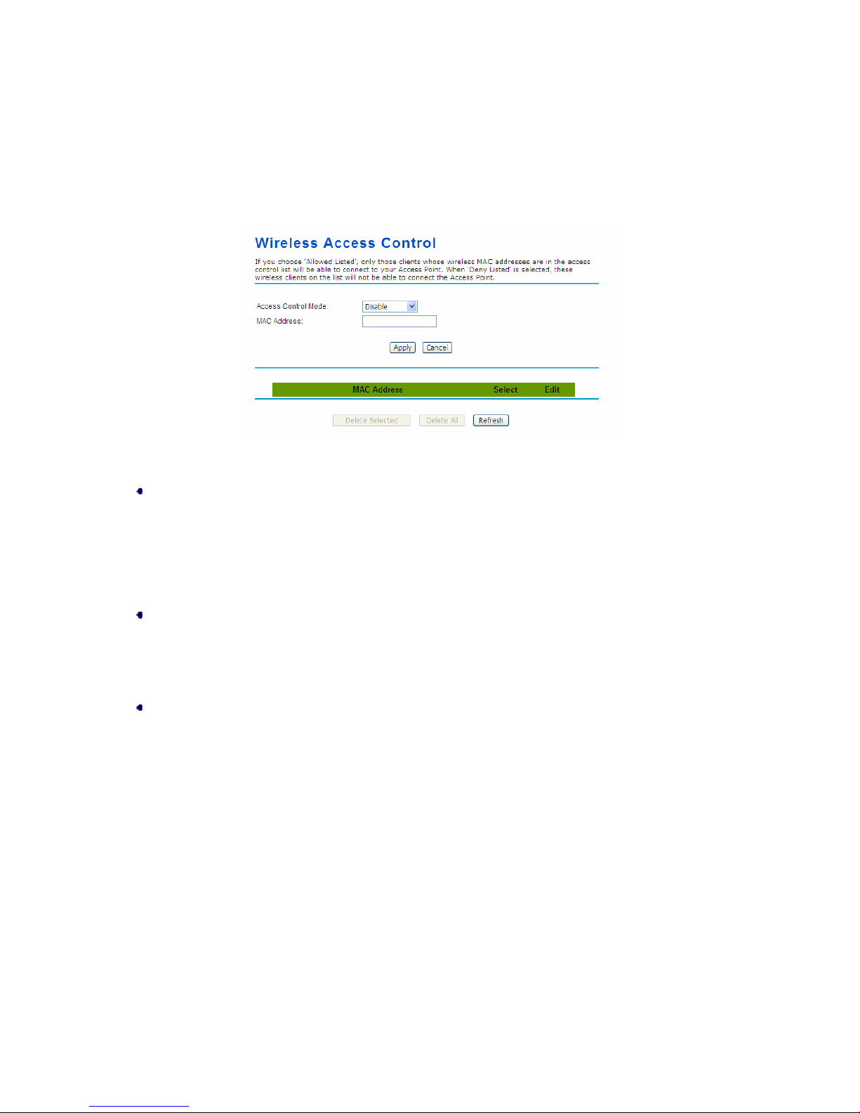
The Access Control appoints the authority to wireless client on accessing JetW ave 2450, thus a further
security mechanism is provided. This function is available only und er AP mode.
Open “Access Control” in “Wireless” as below.
Figure 29 Access Control
Access Control Mode
If you select “Allow Listed”, only those clients whose wireless MAC addresses are in the access
control list will be able to connect to your AP. While when “Deny Listed” is selected, those
wireless clients on the list will not be able to connect the AP.
MAC Address
Enter the MAC address of the wireless client that you would like to list into the access control list,
click “Apply” then it will be added into the table at the bottom.
Delete Selected/All
Check the box before one or more MAC addresses of wireless client(s) that you would like to
cancel, and click “Delete Selected” or “Delete All” to cancel that access control rule.
Page 43
Chapter 4 Advanced Settings Page 33
WDS Settings
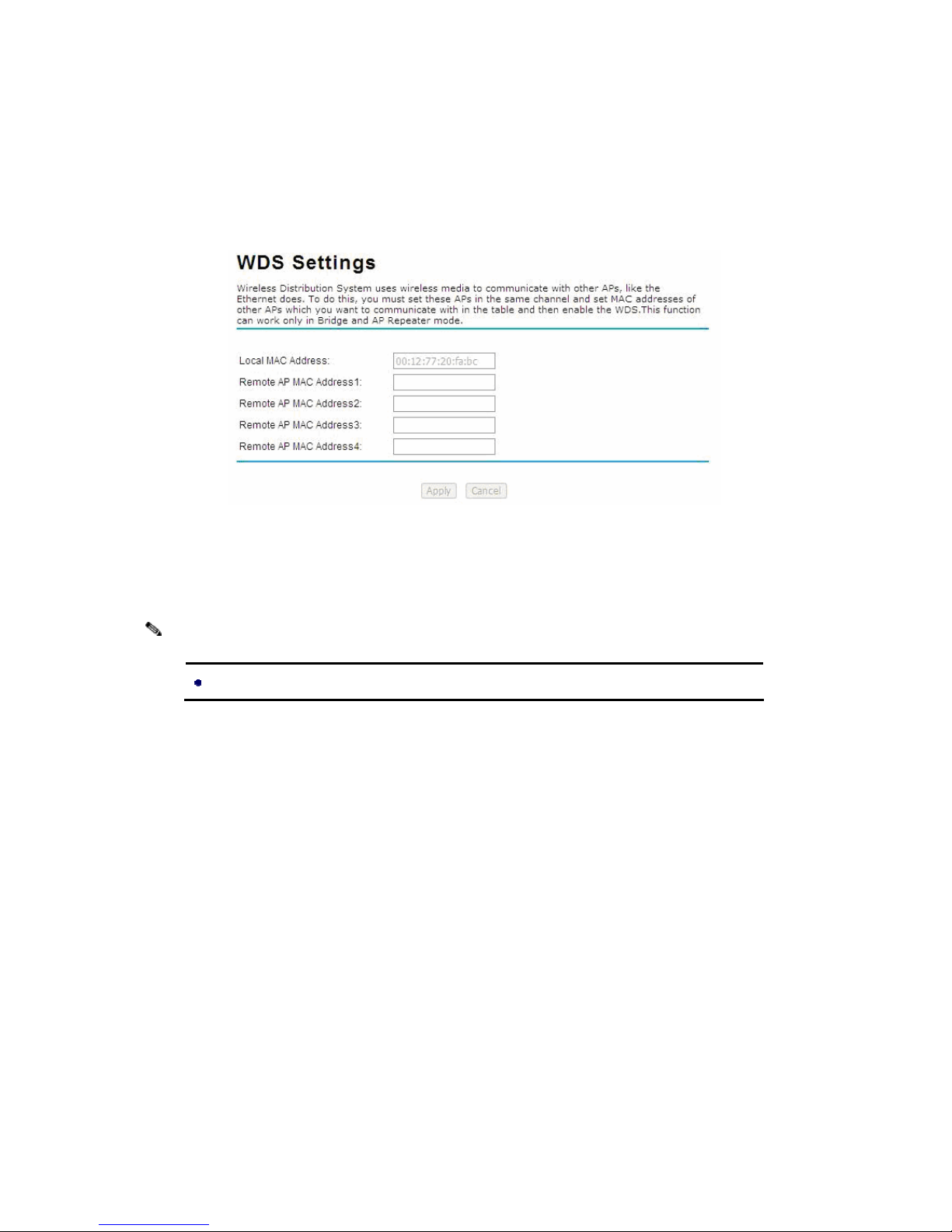
Extend the range of your network without having to use cables to link the Access Points by using the
Wireless Distribution System (WDS): Put simply, you can link the Access Points wirelessly. Open
“WDS Settings” in “Wireless” as below:
Figure 30 WDS Settings
Enter the MAC address of another AP you wirelessly want to connect to into the appropriate field and
click “Apply” to save settings.
Note:
WDS Settings is available only under Bridge and AP Repeater Mode.
Page 44
Chapter 5 Management Page 34
Chapter 5 Management
SNMP Management
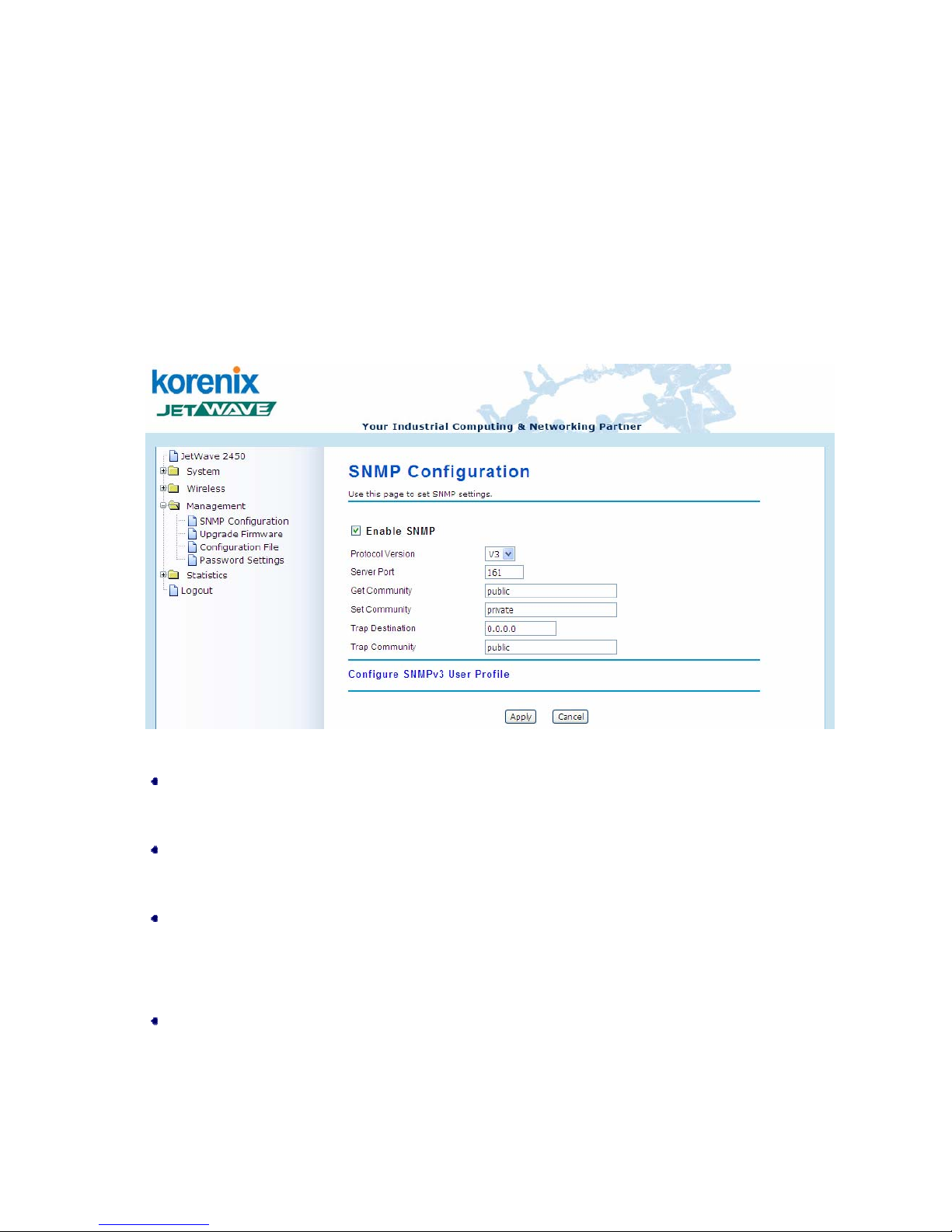
The JetWave 2450 supports SNMP for convenient remote management. Open “SNMP Configuration”
in “Management” shown below. Set the SNMP parameters and obtain MIB file before remote
management.
Figure 31 SNMP Configuration
Enable SNMP
Check this box to enable SNMP settings.
Protocol Version
Select the SNMP version, and keep it identical on the JetWave 2450 and the SNMP manager.
Server Port
Change the server port for a service if needed; however you have to use the same port to use that
service for remote management.
Get Community
Specify the password for the incoming Get and GetNext requests from the management station. By
default, it is set to public and allows all requests.
Page 45
Chapter 5 Management Page 35
Set Community
Specify the password for the incoming Set requests from the management station. By default, it is
set to private.
Trap Destination
Specify the IP address of the station to send the SNMP traps to.
Trap Community
Specify the password sent with each trap to the manager. By default, it is set to public and allows all
requests.
Configure SNMPv3 User Profile
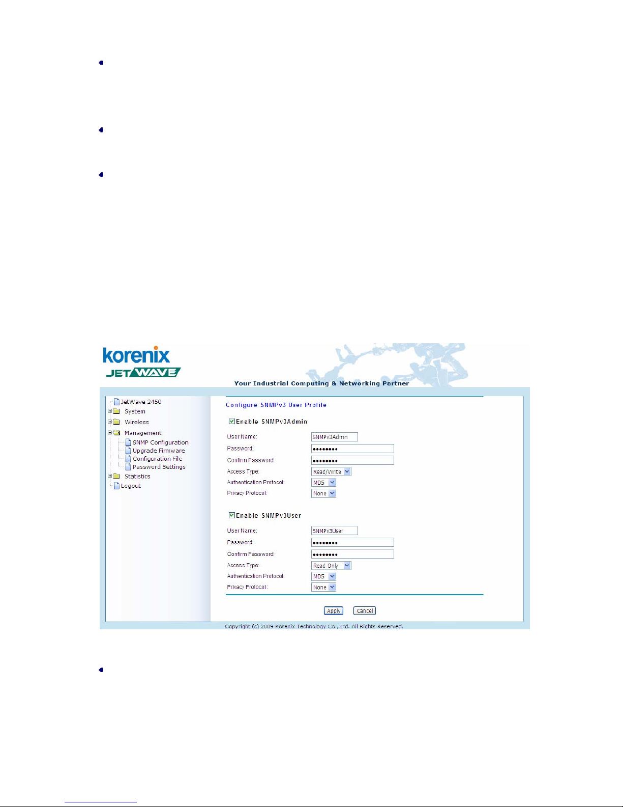
For SNMP protocol version 3, you can click “Configure SNMPv3 User Profile” in blue to set the details
of SNMPv3 user. Check “Enable SNMPv3 Admin/User” in advance and make further configuration.
Figure 32 Configure SNMPv3 User Profile
User Name
Specify a user name for the SNMPv3 administrator or user. Only the SNMP commands carrying this
user name are allowed to access the JetWave 2450.
Page 46
Chapter 5 Management Page 36
Password
Specify a password for the SNMPv3 administrator or user. Only the SNMP commands carrying this
password are allowed to access the JetWave 2450.
Confirm Password
Input that password again to make sure it is your desired one.
Access Type
Select “Read Only” or “Read and Write” accordingly.
Authentication Protocol
Select an authentication algorithm. SHA authentication is stronger than MD5 but is slower.
Privacy Protocol
Specify the encryption method for SNM P communication. None, DES and None are available.
None
: No encryption is applied.
DES
: Data Encryption Standard, it applies a 58-bit key to each 64-bit block of data.
Password
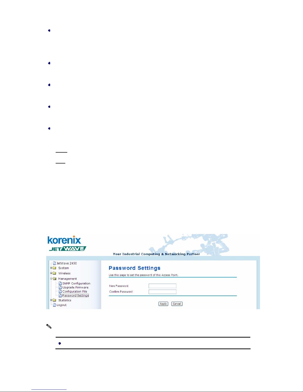
From “Password Settings” in “Management”, you can change the password to manage your JetWave
2450. Enter the new password respectively in “New Password” and “Confirm Password” fields; click
“Apply” to save settings.
Figure 33 Password
Note:
The password is case-sensitive and its length can not exceed 19 characters!
Page 47
Chapter 5 Management Page 37
Upgrade Firmware
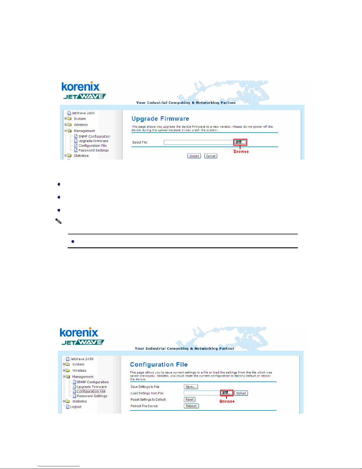
Open “Firmware Upload” in “Management” and follow the steps below to upgrade firmware locally or
remotely through JetWave 2450’s Web:
©
Figure 34 Upgrade Firmware
Click “Browse” to select the firmware file you would like to load;
Click “Upload” to start the upload process;
Wait a moment, the system will reboot after successful upgrade.
Note:
Do NOT cut the power off during upgrade, otherwise the system may crash!
Backup/ Retrieve Settings
It is strongly recommended you back up configuration information in case of something unexpected. If
tragedy hits your device, you may have an access to restore the important files by the backup. All these
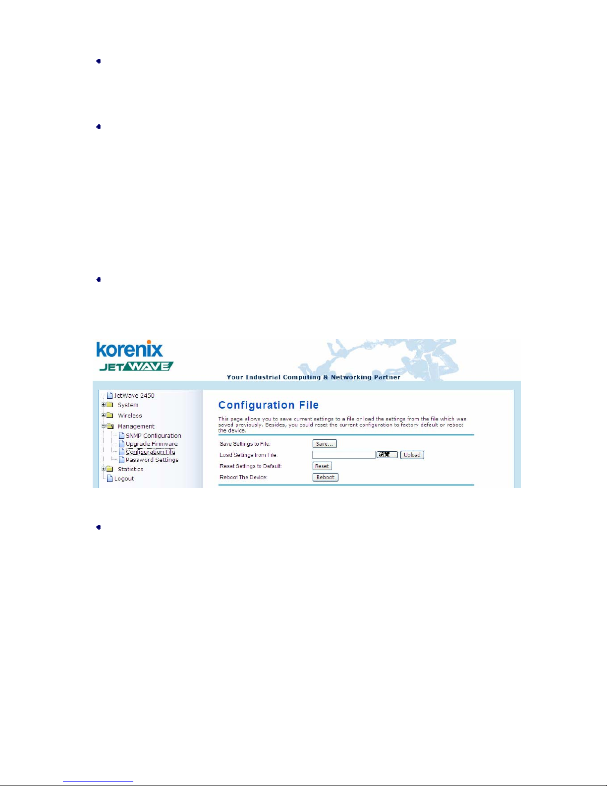
can be done by the local or remote computer. Open “Configuration File” in “Management” as below:
Figure 35 Backup/Retrieve Settings
Page 48
Chapter 5 Management Page 38
Backup Settings
By clicking “Save” a dialog box will popup. Save it, then the configuration file like ap.cfg will be
saved to your local computer.
Retrieve Settings
By clicking “Browse” a file selection menu will appear, select the file you want to load, like ap.cfg;
Click “Upload” to load the file. After automatically rebooting, new settings are applied.
Restore Factory Default Settings
The JetWave 2450 provides two ways to restore the factory default settings:
Restore factory default settings via Web
From “Configuration File”, clicking “Reset” will eliminate all current settings and reboot your device,
then default settings are applied.
Figure 36 Restore Settings
Restore factory default settings via RS-232
If software in JetWave 2450 is unexpect edly cra shed and no longe r reset the unit via Web, you may
do hardware reset via the reset button.
Reboot
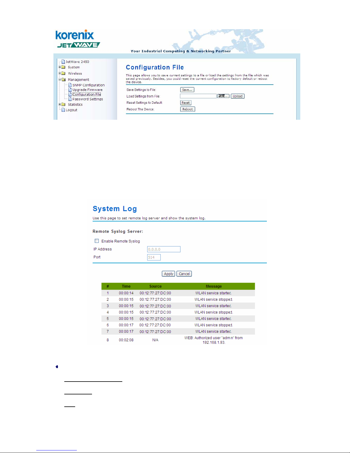
You can reboot your JetWave 2450 from “Configuration File” in “Management” as below:
Click “Reboot” and hit “Yes” upon the appeared prompt to start reboot process. This takes a few
minutes.
Page 49
Chapter 5 Management Page 39
Figure 37 Reboot
System Log
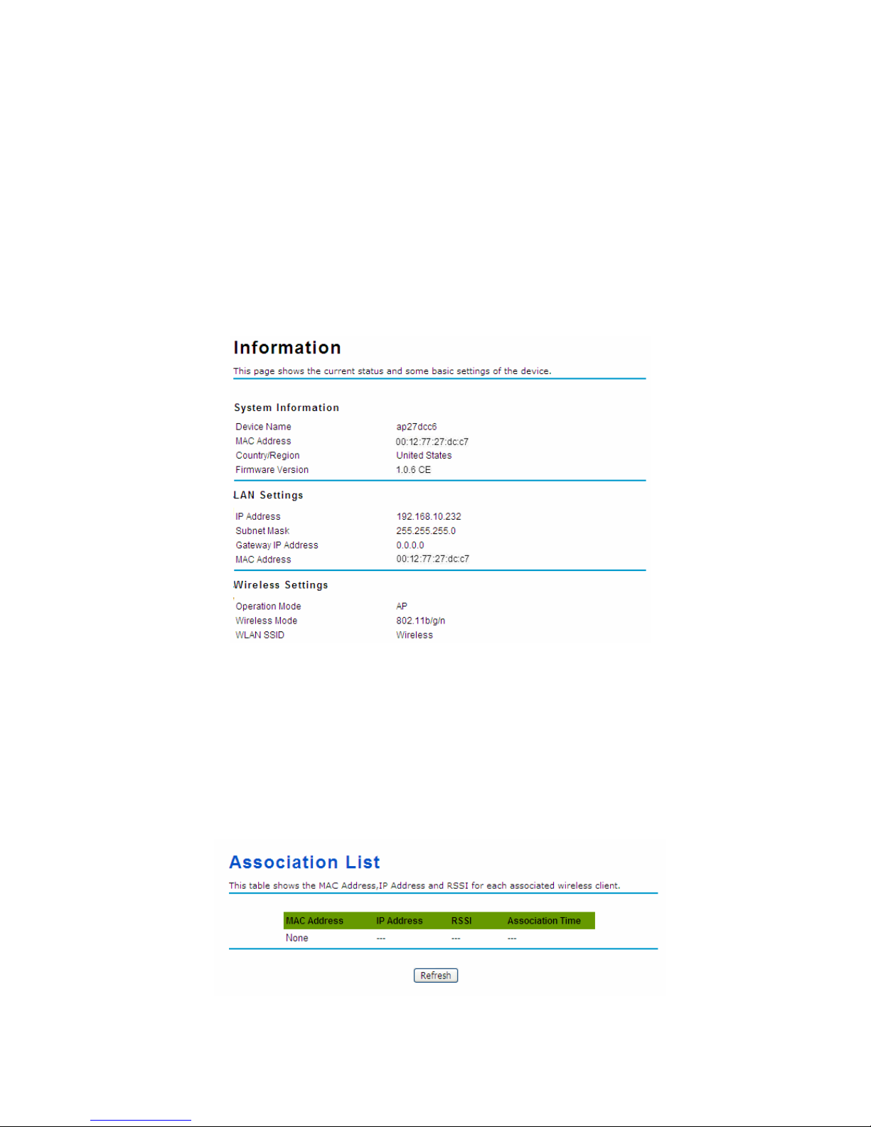
System log is used for recording events occurred on the JetWave 2450, including station connection,
disconnection, system reboot and etc.
Open “System Log” in “Tools” as below.
Figure 38 System Log
Remote Syslog Server
Enable Remote Syslog
: Enable System log or not.
IP Address
: Specify the IP address of the server.
Port
: Specify the port number of the server.
Page 50
Chapter 6 Status Page 40
Chapter 6 Status
View JetWave 2450 Basic Information
Open “Information” in “Status” to check the basic information of JetW ave 2450, which is read only. Click
“Refresh” at the bottom to have the real-time information.
Figure 39 Basic Information
Association List
Open “Association List” in “Connection” from “Status” to check the information of associated wireless
clients. All is read only. Click “Refresh” at the bottom to view the current association list.
Figure 40 Connection
Page 51
Chapter 6 Status Page 41
View Network Flow Statistics
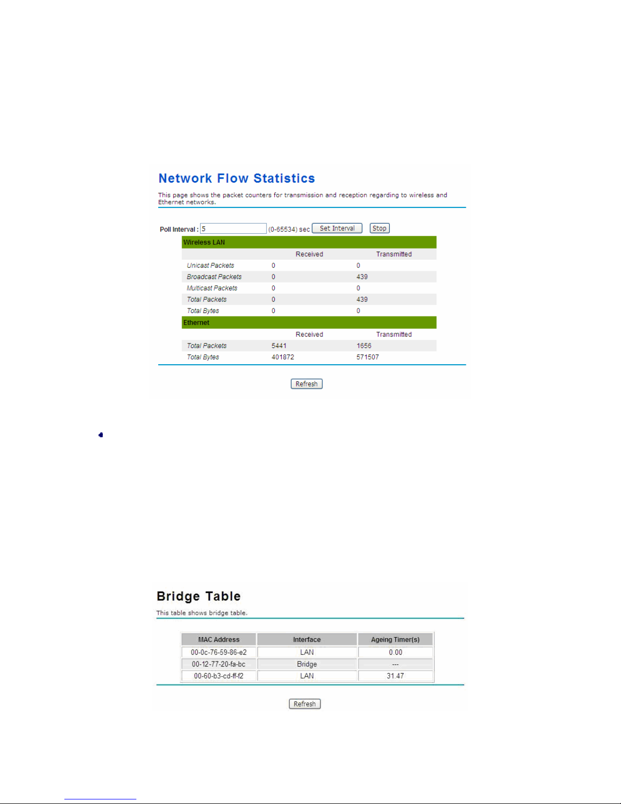
Open “Network Flow” in “Status” to check the data packets received on and transmitted from the
wireless and Ethernet ports. Click “Refresh” to view current statistics.
Figure 41 Network Flow Statistics
Poll Interval
Specify the refresh time interval in the box beside “Poll Interval” and click “Set Interval” to save
settings. “Stop” helps to stop the auto refresh of network flow statistics.
View Bridge Table
Open “Bridge Table” in “Status” as below. Click “Refresh” to view current connected status..
Figure 42 Bridge T able
Page 52
Chapter 6 Status Page 42
View ARP T able
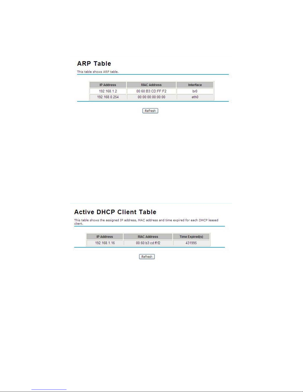
Open “ARP Table” in “Status” as below. Click “Refresh” to view current table.
Figure 43 ARP Table
View Active DHCP Client Table
Open “DHCP Client List” in “Status” as below to check the assigned IP address, MAC address and
time expired for each DHCP leased client. Click “Refresh” to view current table.
Figure 44 DHCP Client Table
Page 53
Chapter 7 Troubleshooting Page 43
Chapter 7 Troubleshooting
This chapter provides troubleshooting procedures for basic problems with the JetWave 2450. For
warranty assistance, contact your service provider or distributor for the pro ce ss.
Q 1. How to know the MAC address of JetWave 2450?
MAC Address distinguishes itself by the unique identity among network devices. For Korenix
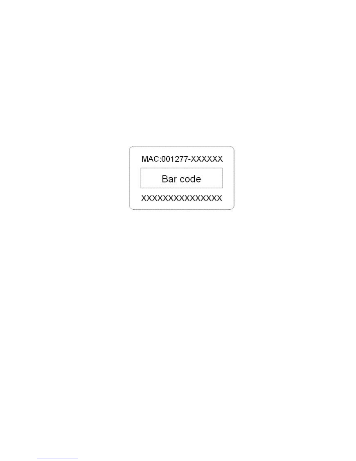
products, the MAC Address is 001277-XXXXXX. There are two ways available to know it.
• Each device has a label posted with the MAC address. Please refer to below.
Figure 15 MAC Address
• On the JetWave 2450 Web-based management interface, you can view the MAC Address
from “View JetWave 24 50 Basic Information”.
Q 2. Wha t if I would like to reset the unit to default settings?
You may restore factory default settings in “Configuration File” from “Management”.
Q 3. Wha t if I would like to backup and retrieve my configuration settings?
You may do the backup by generating a configuration file or retrieve the settings you have backed
up previously in “Configuration File” from “Management”.
Q 4. Wha t if I can not access the Web-based management interface?
Please check the followings:
• Check whether the power supply is OK; Try to power on the unit again.
• Check whether the IP address of PC is correct (in the same network segment as the unit);
• Login the unit via other browsers such as Firefox.
• Hardware reset the unit.
Page 54

Chapter 7 Troubleshooting Page 44
Q 5. What if the wireless connection is not stable after associating with an AP under wireless
client mode?
• Since the JetWave 2450 comes with a built-in directional antenna, it is recommended make
the JetWave 2450 face to the direction whe re the AP is to get the best connection quality.
• In addition, you can start “Site Survey” in “Wireless Basic Settings” to check the signal
strength. If it is weak or unstable (The smaller the number is, the weaker the signal strength
is.), please join other available AP for better connection.
Page 55

Appendix A. ASCII Page 45
Appendix A. ASCII
WEP can be configured with a 64-bit or 128-bit Shared Key (hexadecimal number or ACSII). As
defined, hexadecimal number is represented by 0-9, A-F or a-f; ACSII is represented by 0-9, A-F, a-f or
punctuation. Each one consists of two-digit hexadecimal.
T able 2 ACSII
ASCII
Character
Hex
Equivalent
ASCII
Character
Hex
Equivalent
ASCII
Character
Hex
Equivalent
ASCII
Character
Hex
Equivalent
! 21 9 39 Q 51 i 69
" 22 : 3A R 52 j 6A
# 23 ; 3B S 53 k 6B
$ 24 < 3C T 54 l 6C
% 25 = 3D U 55 m 6D
& 26 > 3E V 56 n 6E
‘ 27 ? 3F W 57 o 6F
( 28 @ 40 X 58 p 70
) 29 A 41 Y 59 q 71
* 2A B 42 Z 5A r 72
+ 2B C 43 [ 5B s 73
, 2C D 44 \ 5C t 74
- 2D E 45 ] 5D u 75
. 2E F 46 ^ 5E v 76
/ 2F G 47 _ 5F w 77
0 30 H 48 ` 60 x 78
1 31 I 49 a 61 y 79
2 32 J 4A b 62 z 7A
3 33 K 4B c 63 { 7B
4 34 L 4C d 64 | 7C
5 35 M 4D e 65 } 7D
6 36 N 4E f 66 ~ 7E
7 37 O 4F g 67
8 38 P 50 h 68
Page 56

Appendix B. GPL Declamation Page 46
Appendix B. GPL Declamation
PUBLIC SOFTW ARE DECLAMATION
In the software we delivered, there may contains some public software, if it is, please read
below carefully:
1. Definition
“Public Software”, when applicable, shall mean that portion of the Licensed Software, in source code
form, set forth in the below Table, and provided under the terms set forth in the Section 5, the indicated
website, the complete license terms can be found.
“Public Software” shall mean each of:
(a) any computer code that contains, or is derived in any manner (in whole or in part) from, any
computer code that is distributed as open source software (e.g. Linux) or similar licensing or
distribution models; and
(b) any software that requires as a condition of use, modification and/or distribution of such software
that such software or other software incorporated into, derived from or distribut ed with such software (i)
be disclosed or distributed in source code form, (ii) be licensed for the purpose of making derivative
works, or (iii) be redistributable at no charge.
Public Software includes, without limitation, software licensed or distributed under any of the following
licenses or distribution models, or licenses or distribution models similar to any of the following: (1)
GNU’s General Public License (GPL) or Lesser/Library GPL (LGPL); (2) the Artistic License (e.g.,
PERL); (3) the Mozilla Public License; (4) the Netscape Public License; (5) the Sun Community
Source License (SCSL); (6) the Sun Industry Source License (SISL); and (7) the Apache Software
license.
2.
Limited Use
Any Public Software provided under the agreement shall be subject to the licenses, terms and
conditions of its model. Licensee hereby agrees to comply with the terms and conditions applicable
Page 57

Appendix B. GPL Declamation Page 47
to any such Public Software, as set forth in its presentation on website.
3. Limited Liability
The supplier hereby express that the supplier shall have no liability for any costs, loss or damages
resulting from Licensee’s breach of the terms and conditions applicable to use, conversion or
combination of the licensed software with or into Public Softwa re.
4. NO WARRANTY
This program or licensed software is distributed in the hope that it will be useful, but WITHOUT ANY
WARRANTY. THE PROGRAM "AS IS" WITHOUT WARRANTY OF ANY KIND, EITHER EXPRESSED
OR IMPLIED, INCLUDING, BUT NOT LIMITED TO, THE IMPLIED WARRANTIES OF
MERCHANTABILITY AND FITNESS FOR A PARTICULAR PURPOSE. THE ENTIRE RISK AS TO
THE QUALITY AND PERFORMANCE OF THE PROGRAM IS WITH LICENSEE.
5. Public Software Name and Description
T able 3 Public Software Name and Description
Program
Name
Copy Right Description Origin
Sour Code
Licenses or Distribution
Models or its special
license terms
License Terms
Website
Reference
Redboot
Copyright (C) 1998,
1999, 2000, 2001, 2002,
2003 Red Hat, Inc.
ftp://ftp.ge
s.redhat.c
om/private
/gnupro-xs
cale-03042
2/redboot-i
ntel-xscale
-030630.tar
.Z
eCos License http://sources.re
dhat.com/ecos/e
cos-license/
Busybox
http://www
.busybox.
net/downl
oads/busy
box-1.01.ta
r.bz2
GNU GENERAL PUBLIC
LICENSE Version 2
http://www.gnu.o
rg/licenses/old-li
censes/gpl-2.0.ht
ml
brctl
Copyright (C) 2000
Lennert Buytenhek
http://nchc
.dl.sourcef
orge.net/s
GNU GENERAL PUBLIC
LICENSE Version 2
http://www.gnu.o
rg/licenses/old-li
censes/gpl-2.0.ht
Page 58

Appendix B. GPL Declamation Page 48
ourceforg
e/bridge/br
idge-utils-
1.0.6.tar.gz
ml
dropbear
Copyright (c)
2002-2006 Matt
Johnston
Portions copyright (c)
2004 Mihnea
Stoenescu
http://matt.
ucc.asn.au
/dropbear/
dropbear-
0.51.tar.bz
2
GNU GENERAL PUBLIC
LICENSE Version 2
http://www.gnu.o
rg/licenses/old-li
censes/gpl-2.0.ht
ml
hostapd
Copyright (c)
2002-2006, Jouni
Malinen
<[email protected]>
and
contributors
http://host
ap.epitest.
fi/releases/
hostapd-0.
4.8.tar.gz
GNU GENERAL PUBLIC
LICENSE Version 2
http://www.gnu.o
rg/licenses/old-li
censes/gpl-2.0.ht
ml
wpa_sup
plicant
Copyright (c)
2003-2005, Jouni
Malinen
<[email protected]>
and
contributors
http://host
ap.epitest.
fi/releases/
wpa_suppl
icant-0.4.7.
tar.gz
GNU GENERAL PUBLIC
LICENSE Version 2
http://www.gnu.o
rg/licenses/old-li
censes/gpl-2.0.ht
ml
mtdutil
ftp://ftp.uk.
linux.org/p
ub/people/
dwmw2/mt
d/cvs/mtd/
util/
GNU GENERAL PUBLIC
LICENSE Version 2
http://www.gnu.o
rg/licenses/old-li
censes/gpl-2.0.ht
ml
ntpclient
Copyright 1997, 1999,
2000, 2003 Larry
Doolittle
http://dooli
ttle.icarus.
com/ntpcli
ent/ntpclie
nt_2003_1
94.tar.gz
GNU GENERAL PUBLIC
LICENSE Version 2
http://www.gnu.o
rg/licenses/old-li
censes/gpl-2.0.ht
ml
procps
Author: Albert Cahalan,
Michael K. Johnson,
Jim Warner, etc.
http://proc
ps.sourcef
orge.net/p
rocps-3.2.
7.tar.gz
GNU GENERAL PUBLIC
LICENSE Version 2
GNU LIBRARY
GENERAL PUBLIC
LICENSE Version 2
http://www.gnu.o
rg/licenses/old-li
censes/gpl-2.0.ht
ml
http://www.gnu.o
rg/licenses/old-li
censes/library.ht
ml
vsftpd
Author: Chris Evans ftp://vsftpd
.beasts.or
g/users/ce
GNU GENERAL PUBLIC
LICENSE Version 2
http://www.gnu.o
rg/licenses/old-li
censes/gpl-2.0.ht
Page 59

Appendix B. GPL Declamation Page 49
vans/vsftp
d-1.1.2.tar.
gz
ml
linux
ftp://ftp.ker
nel.org/pu
b/linux/ker
nel/v2.6/lin
ux-2.6.20.3
.tar.bz2
GNU GENERAL PUBLIC
LICENSE Version 2
http://www.gnu.o
rg/licenses/old-li
censes/gpl-2.0.ht
ml
 Loading...