

Korenix JetWave2411-EU, JetWave2411-AU, JetWave2111-AU, JetWave 2414-E, JetWave 2414-A User Manual
...
JetWave 2111/2411 Series
Wireless LTE Gateway
User Manual
V1.0 Mar.18, 2019

JetWave 2111/2411 Series User Manual
Copyright
Copyright © 2014 all rights reserved. No part of this publication may be reproduced, adapted, stored in
a retrieval system, translated into any language, or transmitted in any form or by any means without
the written permission of the supplier.
About This Manual
This user manual is intended to guide professional installer to install the JetWave 2111/2411 and how
to build the infrastructure centered on it. It includes procedures to assist you in avoiding unforeseen
problems.
Conventions
For your attention on important parts, special characters and patterns are used in this manual:
This indicates an important note that you must pay attention to.
The Blue Wording is important note that you must pay attention to.
The Blue Wording with Big Case is very important note you must pay more attention to.
This indicates a warning or caution that you have to abide.
The Red wording is very important you must avoid.
Bold: Indicates the function, important words, and so on.
Note:
Warning:

JetWave 2111/2411 Series User Manual
Federal Communication Commission Interference Statement
This equipment has been tested and found to comply with the limits for a Class B digital device, pursuant
to Part 15 of the FCC Rules. These limits are designed to provide reasonable protection against harmful
interference in a residential installation. This equipment generates uses and can radiate radio frequency
energy and, if not installed and used in accordance with the instructions, may cause harmful
interference to radio communications. However, there is no guarantee that interference will not occur
in a particular installation. If this equipment does cause harmful interference to radio or television
reception, which can be determined by turning the equipment off and on, the user is encouraged to try
to correct the interference by one of the following measures:
- Reorient or relocate the receiving antenna.
- Increase the separation between the equipment and receiver.
- Connect the equipment into an outlet on a circuit different from that to which the receiver is
connected.
- Consult the dealer or an experienced radio/TV technician for help.
This device complies with Part 15 of the FCC Rules. Operation is subject to the following two conditions:
(1) This device may not cause harmful interference, and (2) this device must accept any interference
received, including interference that may cause undesired operation.
FCC Caution: Any changes or modifications not expressly approved by the party responsible for
compliance could void the user's authority to operate this equipment.

JetWave 2111/2411 Series User Manual
FCC Radiation Exposure Statement:
This equipment complies with FCC radiation exposure limits set forth for an uncontrolled environment.
To avoid the possibility of exceeding radio frequency exposure limits, you shall beep a distance of at
least 100cm between you and the antenna of the installed equipment. This transmitter must not be colocated or operating in conjunction with any other antenna or transmitter.
The availability of some specific channels and/or operational frequency bands are country
dependent and are firmware programmed at the factory to match the intended destination. The
firmware setting is not accessible by the end user.

JetWave 2111/2411 Series User Manual
Content
JetWave 2111/2411 Series .......................................................................................................................................... 1
Chapter 1 Introduction ........................................................................................................................................... 1
1.1
Introduction ........................................................................................................................................ 2
1.2
JetWave 2111/2411 Series Appearance ........................................................................................... 3
1.3
JetWave 2111/2411 Major Features ................................................................................................. 4
1.4 Product Package ................................................................................................................................ 5
Chapter 2 Hardware Installation .......................................................................................................................... 6
2.1
Professional Installation Required ................................................................................................ 10
2.2
Power Installation ............................................................................................................................ 11
2.3 I/O Configuration ............................................................................................................................. 12
2.4 LED Indicator ................................................................................................................................... 17
2.5 Using the External Antenna .............................................................................................................. 18
Chapter 3 Prepare for Management ................................................................................................................... 19
3.1
Basic Factory Default Settings ....................................................................................................... 20
3.2
System Requirements ..................................................................................................................... 22
3.3
How to Login the Web-based Interface ......................................................................................... 22
3.4
Fail to login the Web GUI ................................................................................................................ 23
3.5
How to login the CLI ........................................................................................................................ 24
3.6
Discovery Utility – Korenix View Utility ......................................................................................... 25
Chapter 4 Web GUI Configuration ..................................................................................................................... 26
4.1 Status ................................................................................................................................................ 27
4.2 System ................................................................................................................................................ 30
4.4 Cellular ................................................................................................................................................ 43
4.5 GPS ................................................................................................................................................... 49

JetWave 2111/2411 Series User Manual
4.6 VPN.................................................................................................................................................... 50
4.7 Management ..................................................................................................................................... 56
4.8 Tools .................................................................................................................................................. 63
4.9 Main Entry ........................................................................................................................................ 69
Chapter 5 Configuration – SNMP, CLI, View Utility ............................................................................................ 71
5.1
SNMP ................................................................................................................................................ 72
5.2
Command Line Interface (CLI) ..................................................................................................... 113
5.3
Korenix View Utility ....................................................................................................................... 120
Chapter 6 Troubleshooting ................................................................................................................................ 123
6.1
General Question ........................................................................................................................... 124
6.2
Wireless/Cellular ............................................................................................................................ 125
6.3
Appendix ........................................................................................................................................ 127
Revision History ...................................................................................................................................................... 133

JetWave 2111/2411 Series User Manual
Chapter 1
Introduction

JetWave 2111/2411 Series User Manual
Chapter 1 Introduction
1.1
Introduction
The user manual is applied to Korenix JetWave 2111/2411 LTE IP Gateway. The 2 product series
equips with the same LTE technology, the same hardware/software platform and the same installation
consideration for indoor or outdoor field box.
For detail product specification, please download the latest datasheet from Korenix web site.
JetWave 2111/2411 Series User Manual
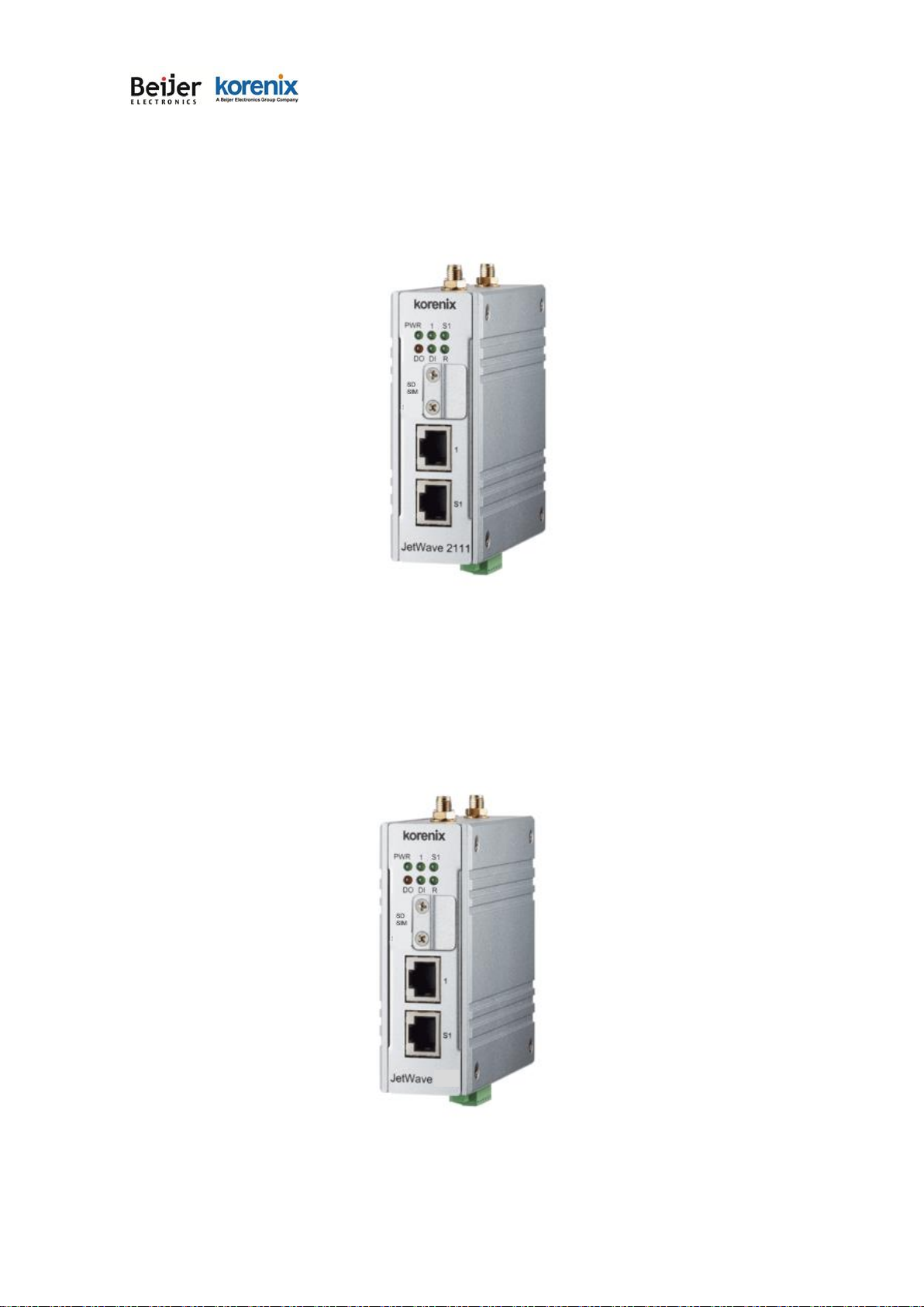
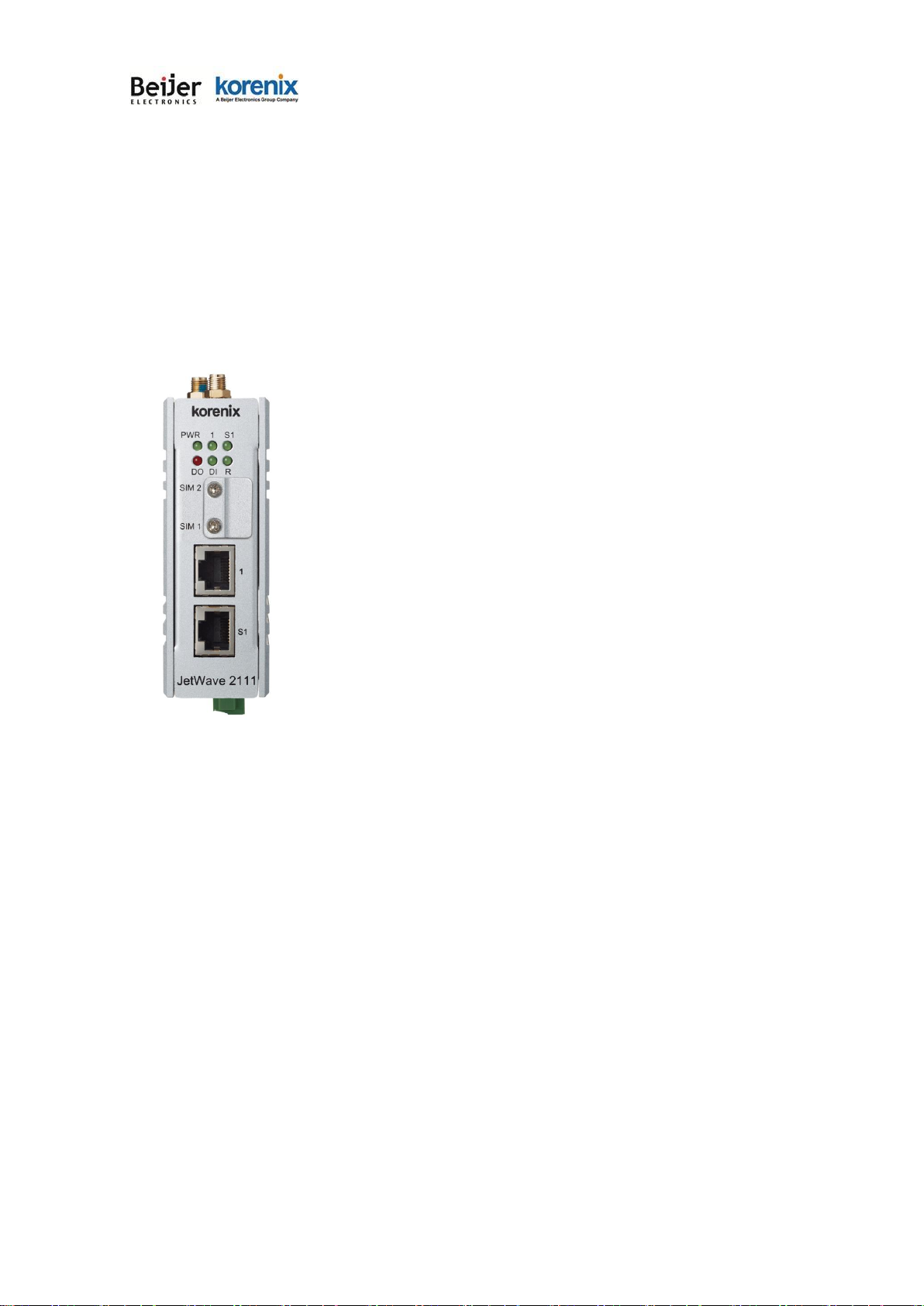
1.2
JetWave 2111/2411 Series Appearance
Figure - JetWave 2111 Appearance
Figure - JetWave 2411 Appearance
2411

JetWave 2111/2411 Series User Manual
1.3
JetWave 2111/2411 Major Features
Model Name
LTE Bandwidth
Ethernet
Serial
DI/DO
Cellular
JetWave2111-EU
Cat 1
10M DL/5M UL
1 x FE
1 (3 in 1)
1DI,1DO
FDD-LTE - B1/ B3/ B5/ B7/ B8/ B20
TDD-LTE - B38/ B40 /B41
WCDA -B1/ B5/ B8
JetWave2111-AU
Cat 1
10M DL/5M UL
1 x FE
1 (3 in 1)
1DI,1DO
FDD-LTE -B1/ B2/ B3/ B4/ B5/ B7/ B8/ B28
TDD-LTE - B40
WCDMA-B1/ B2/ B5/ B8
JetWave2411-EU
Cat 4
150M DL/50M UL
1 x FE
1 (3 in 1)
1DI,1DO
FDD-LTE - B1/ B3/ B5/ B7/ B8/ B20
TDD-LTE - B38/ B40 /B41
WCDA -B1/ B5/ B8
JetWave2411-AU
Cat 4
150M DL/50M UL
1 x FE
1 (3 in 1)
1DI,1DO
FDD-LTE -B1/ B2/ B3/ B4/ B5/ B7/ B8/ B28
TDD-LTE - B40
WCDMA-B1/ B2/ B5/ B8
• Industrial Slim Size Cellular Router/IP Gateway
• JetWave2411 (LTE Cat 4) max. 150M DL/50M UL
• JetWave2111 (LTE Cat 1) max. 10M DL/5M UL
• One MicroSD card slot support
• 1 DI + 1 DO
• 1 ports RS232/422/485 3 in 1 (RJ45 type)
• 1 Fast Ethernet Port
• VPN/Firewall/DMZ and Secure VPN Connectivity
• LAN to 4G/LTE Routing
• Remote management by Web GUI, SNMP, Auto IP Report, Korenix View, Mobile Manager
• 24V(9~30V) DC power input
• Wide Temperature, Heavy Industrial Grade design
• Support GPS (Optional)

JetWave 2111/2411 Series User Manual
1.4 Product Package
The product package you have received should contain the following items. If any of them are not
included or damaged, please contact your local vendor for support.
Package:
JetWave 2111/2411 Unit (depends on the model you purchase) Pre-installed Embedded LTE
Module (depends on the model you purchase)
Default Antenna 2
Din-Rail Mounting Kit
6-pin Power/DI+DO connector
Quick Installation Guide
Note: Please download the Utility, User Manual from Korenix Web Site.
Note 1: Check the Korenix web site order information for new accessories, new version user manual,
MIB file, firmware and Utility.
Note 2: Different model needs different number of the accessories. If you are not familiar with the
feature of the accessories, please consult with our Sales or Technical Service Engineer.

JetWave 2111/2411 Series User Manual
Chapter
2 Hardware
Installation

JetWave 2111/2411 Series User Manual
Page 10
Chapter 2 Hardware Installation
This chapter describes safety precautions and product information before installing JetWave
2111/2411 Series.
2.1
Professional Installation Required
1.
Please seek assistance from a professional installer for field installation or professional IT
Engineer for indoor installation.
2.
The JetWave 2111/2411 series is distributed through distributors and system installers with
professional technicians and will not be sold directly through retail stores.

JetWave 2111/2411 Series User Manual
Page 11
2.2
Power Installation
2.2.1
DC Input
1.
There is one 6-pin terminal block within the package for screwing the DC wires. It is a good
practice to turn off the system power, and to unplug power terminal block before making wire
connections.
2.
Insert the positive and negative wires into the V+ and V- contact on the terminal block
connector. Tighten the wire-clamp screws to prevent DC wires from being loosened. The
range of the suitable electric wire is from 9 to 30 AWG.
3.
The typical and suggest power source is DC 24V, the acceptable range is range from
9~30V.
4.
The single DC power can be redundant. You can connect one power to typical power source
and the other to battery/UPS as backup.

JetWave 2111/2411 Series User Manual
Page 12
2.3 I/O Configuration
2.3.1
Wiring your Ethernet Port
There are 1 Fast Ethernet port. The 1 port is standard RJ-45 form factor. They can support
10Base-TX, 100Base-TX. The 10/100Base-TX also support both full or half duplex mode. All the
Ethernet ports will auto-detect the signal from connected devices to negotiate the link speed and
duplex mode. Auto MDI/MDIX allows users to connect another switch, hub or workstation without
changing straight through or crossover cables. In some cases, the MDI/MDI-X may requests the
connected device support auto-negotiation.
Available Cable Type:
10Base‐T: 2‐pair UTP/STP Cat. 3, 4, 5 cable (100m)
100 Base‐TX: 2/4‐ pair UTP/STP Cat. 5 cable (100m)
Wiring STP Cable: STP (Shielded Twisted Pair) cable is preferred. The device is an
EN50121-4 certificated product and usually install in harsh environment, part of the EMS
protection are based on STP cable, for example the Surge protection of front Ethernet ports. STP
cable can provide better field protection. It is MUST for the device installation in harsh
environment.
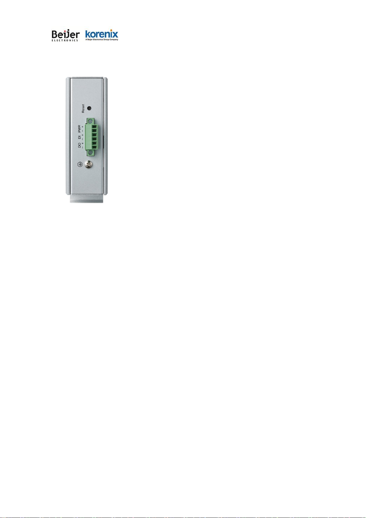
2.3.2
Reset
There is one Reset button located on the front of the device. This is design for user to reboot the
system port or force reset the configuration to default. The function is depended on how much
time you press the button.
Press 3 seconds to reboot the device.
Press more than 7 seconds can reset the configuration to default.
JetWave 2111/2411 Series User Manual
Page 13
2.3.3
Serial Port
There is one RJ45 type serial port for serial communication on JetWave 2111/2411(S1). The
serial port is designed for Serial over Cellular communication. The port supports RS232/422/485
3-in-1, and up to 460.8kbps baud rate. The software supports TCP/UDP connection.
JetWave 2111/2411 Series User Manual
Page 14
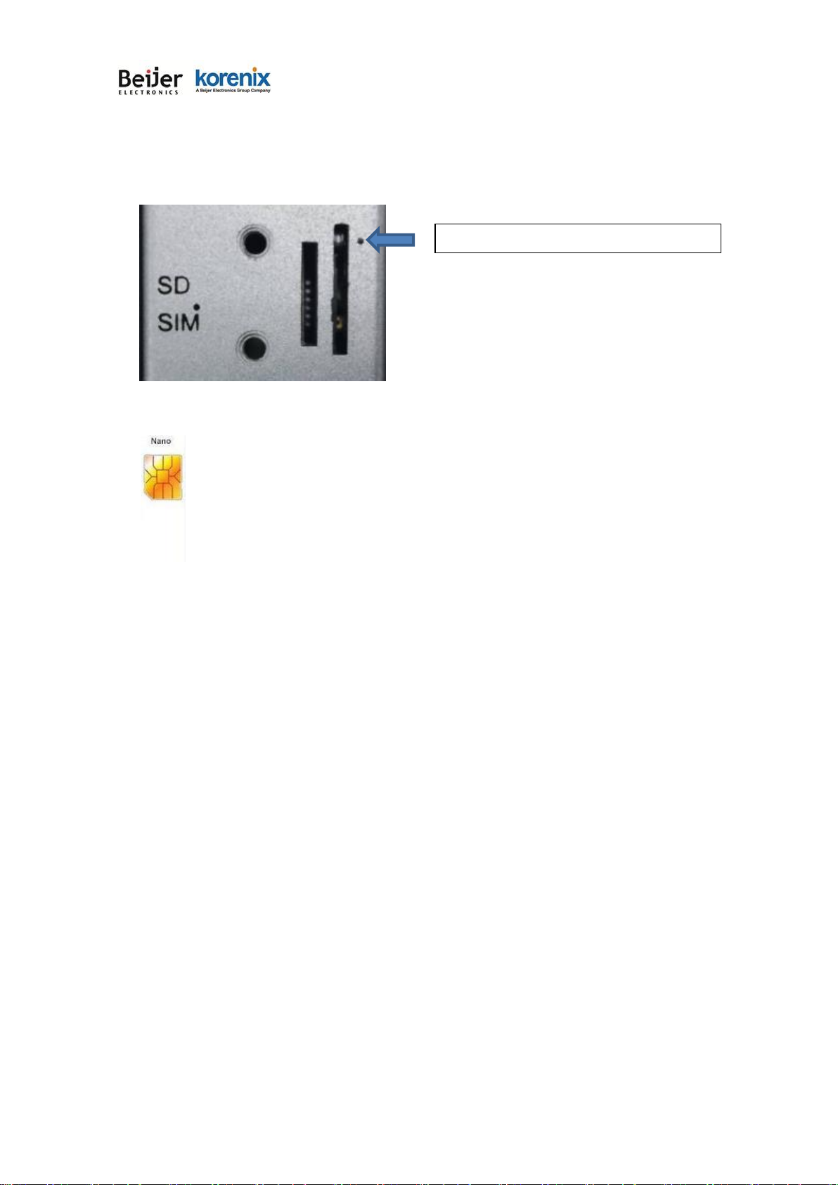
2.3.4
SIM Socket
The JetWave 2111/2411 provides one external SIM (Subscriber Identity Module) socket to store
the LTE SIM card. Loosen the screw and then you can plug in the SIM card.
The supported SIM card is Nano-SIM.
Note: While you prepare to plug in the SIM card, please remember to power off the system first.
This is a MUST step, it allows the JetWave 2111/2411 system to detect the SIM card while
booting up.
SIM connecter
JetWave 2111/2411 Series User Manual
Page 15
2.3.5
Digital Input
The system provides 1 digital input in the bottom side of the device.
It allows users to connect the termination units’ digital output and manage/monitor the status of
the connected unit. The Digital Input pin can be pulled high or low; thus the connected equipment
can actively drive these pins high or low. The embedded software UI allows you to read and set
the value to the connected device. The power input voltage of logic low is DC 0~10V. Logic high
is DC 11~30V. Wiring digital input is exactly the same as wiring power input.
2.3.6
Digital Output
The system provides 1 digital output. It is also known as Relay Output. The relay contacts are
energized (open) for normal operation and will close for fault conditions. The fault conditions
include Ethernet port link break which can be configured in the management interface. Wiring
digital output is exactly the same as wiring power input.

JetWave 2111/2411 Series User Manual
Page 16
2.3.7
Ground
To ensure the system will not be damaged by noise or any electrical shock, we suggest you to
make exact connection with the Earth Ground. There is one earth ground screw on the bottom
side of the device. Loosen the earth ground screw then tighten the screw after earth ground wire
is connected.
JetWave 2111/2411 Series User Manual
Page 17
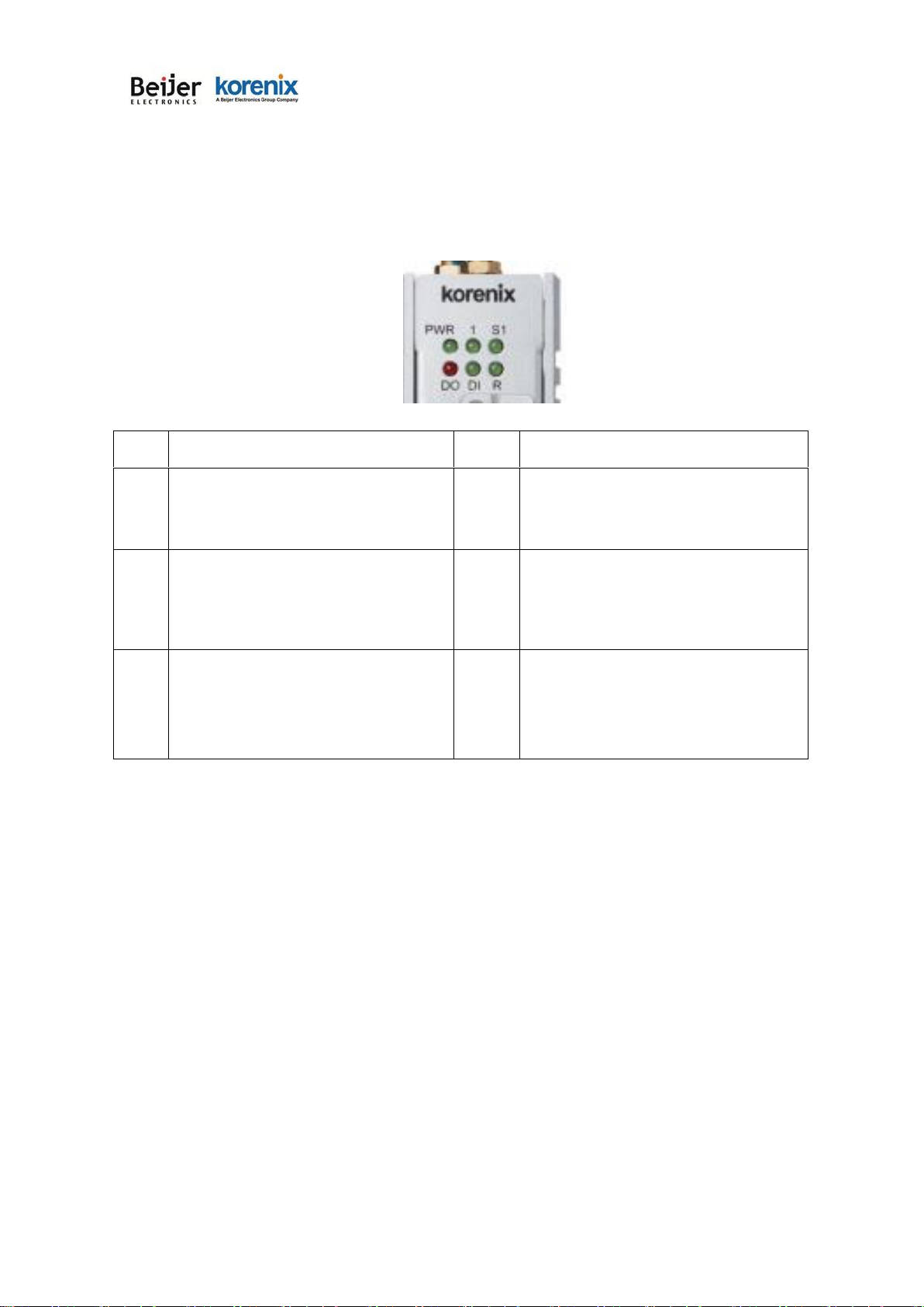
2.4 LED Indicator
The following table indicates the LED of your device.
LED
Indication
LED
Indication
PWR
Power 1 Status
Green ON = System ON
DO
Digital Output Status
Red ON = The Relay is ON. It may
indicate the alarm of specific events.
1
Ethernet Port 1 Status.
Green ON = Eth 1 is Link Up.
Green Blinking = Eth 1 is Activating
DI
Digital Intput Status
Red ON = The Relay is ON. It may
indicate the alarm of specific events.
S1
Serial Port 1 Status.
Green ON = S1 is Link Up.
Green Blinking = S1 is Activating
R
Status of the Radio
Green ON = Radio is activated

JetWave 2111/2411 Series User Manual
Page 18
2.5 Using the External Antenna
Consult your system integrator or our technical support engineer to choose the suitable external
antenna with SMA-type or N-Type connector for your application. Different antenna supports
different bands, polarization and different range of coverage.
Antenna Socket of the Gateway:
LTE2: SMA connector LTE antenna
GPS: SMA connector GPS antenna (not included in the package please purchase if needed)
LTE1: SMA connector LTE antenna
Lightning Arrestor:
While you install the external antenna in outside area, the Arrestor is a must accessory to avoid
the environment attack through the antenna. The arrestor protects the insulation and conductors
of the system from the damaging effects of lightning. For example the JWA-Arrestor-5803 is 06G Arrestor for N-Type Antenna.

JetWave 2111/2411 Series User Manual
Page 19
Chapter 3
Prepare for Management
JetWave 2111/2411 Series User Manual
Page 20
Chapter 3 Prepare for Management
The JetWave 2111/2411 Series supports Web GUI Configuration, Simple Network Management
Protocol (SNMP), Telnet and Diagnostic Command Line Interface for management and Window Utility
helps you discover the device cross network, basic IP setting, firmware management…etc.
This chapter describes the preparation for management. In your first time access the device, you can
refer to the Basic Factory Default Settings to know the default settings and the default IP of the device.
The chapter also tells you how to login the Web-based interface, Diagnostic Console. If you forget IP
address you changed, you can use Korenix View Utility (refer to next chapter) to discover the devices’
IP address and then access it.
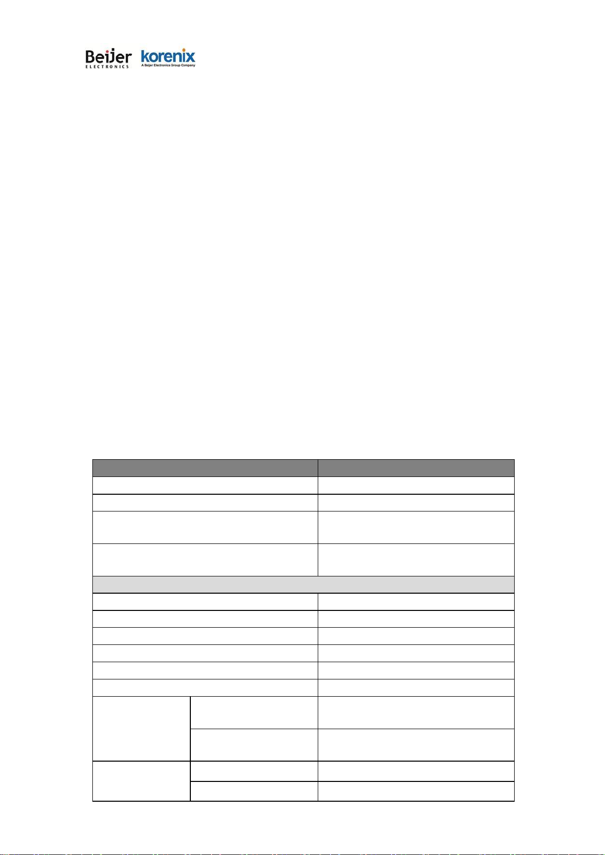
3.1
Basic Factory Default Settings
We’ll elaborate the JetWave 2111/2411 Series basic factory default settings. You can re-acquire
these parameters by default. This info is easier for you to find the device and access the switch’s
configuration interface. For further info, please refer to configuration guide of the feature set.
Table 1 JetWave 2111/2411 Basic Factory Default Settings
Features
Factory Default Settings
Username
admin
Password
admin
Model Name
JetWave2111 (2411 depends on
which model you access)
Device Name
korenixXXXXXX (X represents the last 6
digits of Ethernet MAC address)
Default IP at Bridge Mode (JetWave 2111/2411 Default)
Access Type
Static IP
IP Address
192.168.10.1
Subnet Mask
255.255.255.0
Default Gateway
0.0.0.0
Primary DNS Server
0.0.0.0
Secondary DNS Server
0.0.0.0
Remote Settings
Remote Management
Privacy
Telnet, SNMP, SNMP Trap, Email Alert
Even Warning Type
WLAN association, Authentication fail,
Configuration Changed
Version
2/3
Server Port:
161
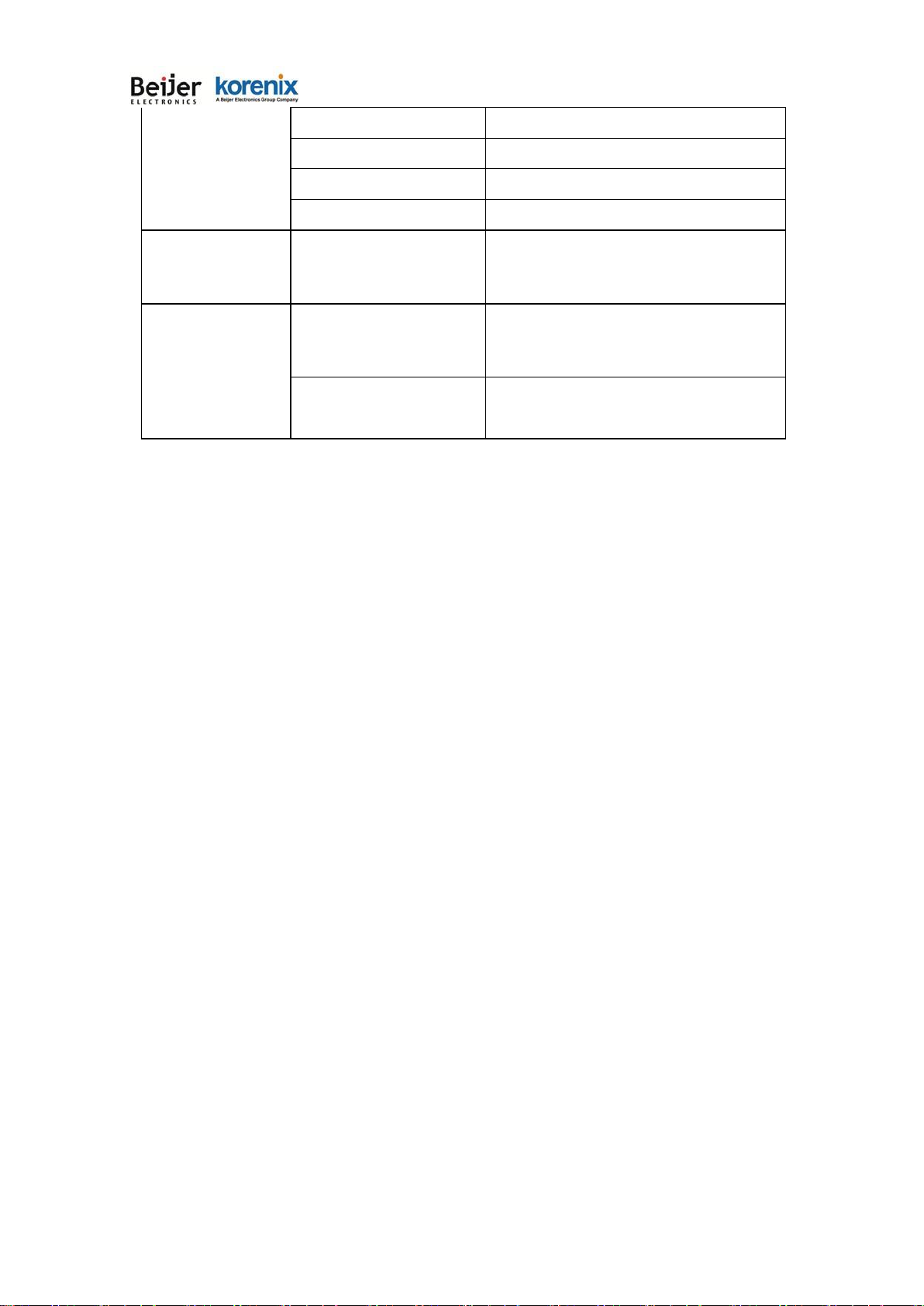
JetWave 2111/2411 Series User Manual
Page 21
SNMP
Get Community
Public
Set Community
Private
Trap Destination
0.0.0.0
Trap Community
Public
Korenix View Utility
Device Search, IP Assign,
Basic Tool, Wireless Panel
Diagnostic CLI
Baud Rate
115,200
Parameter
N, 8, 1

JetWave 2111/2411 Series User Manual
Page 22
It is Important to change all the default settings of the Gateway, includes the User
Name, Password, Default IP Address, Default SSID, SNMP Community Name and
configure Wireless Security to secure your network.
3.2
System Requirements
Before configuration, please make sure your system meets the following requirements:
A computer coupled with 10/100Base-T(X) adapter;
Configure the computer with a static IP address of 192.168.10.x (X cannot be 0, 1, nor 255) A Web
browser on PC for configuration such as Microsoft Internet Explorer 6.0 or above, Google Chrome or
Firefox.
Note: If you want to do throughput test, not just configure the switch, please notice that the
throughput of the high performance and low performance CPU must be different.
3.3
How to Login the Web-based Interface
The system provides you with user-friendly Web-based management tool.
Open Web browser and enter the IP address (Default: 192.168.10.1) into the address field. You will
see the WELCOME page as below.
Figure – Web GUI Login Page
Warning:
JetWave 2111/2411 Series User Manual
Page 23
Enter the name of Account (Default: admin) and password (Default: admin) respectively and click
“Login” to login the main page of the device. As you can see, this management interface provides main
options in the above, which are Status, System, Management, Tools, Save, Reboot and Logout.
Figure - Main Page
The username and password are case-sensitive!
3.4
Fail to login the Web GUI
If you failed to login the web GUI, there are something you can do for troubleshooting.
1.
Please disable the firewall setting of your browser. The firewall setting may block the connection
from your PC to the device. The firewall may stop the firmware upgrade, configuration backup and
restore as well. Note that after finished the setting, re-enable your firewall to protect your PC.
2.
Check the IP Setting, your PC and managed device must be located within the same subnet.
3.
The Web UI connection session of the device will be logged out automatically if you don’t give any
input after 30 seconds. After logged out, you should re-login and key in correct user name and
password again.
Note:
JetWave 2111/2411 Series User Manual
Page 24
3.5
How to login the CLI
Telnet/SSH:
You can connect to the device by Telnet and the command lines. Below are the steps to open Telnet
connection to the switch.
1.
Go to Start -> Run -> cmd. And then press Enter
2.
Type the Telnet 192.168.10.1 (or the IP address of the switch). And then press Enter
Note that the Telnet.exe file is not provided after Window 7. You can download it from Microsoft web site. Or
you can use 3rd Party tool, for example the Putty.
3rd Party tool:
Download PuTTY: http://www.chiark.greenend.org.uk/~sgtatham/putty/download.html
The copyright of PuTTY is belonged to Putty. We don’t have any contract with them. Please follow the
shareware policy of their company.
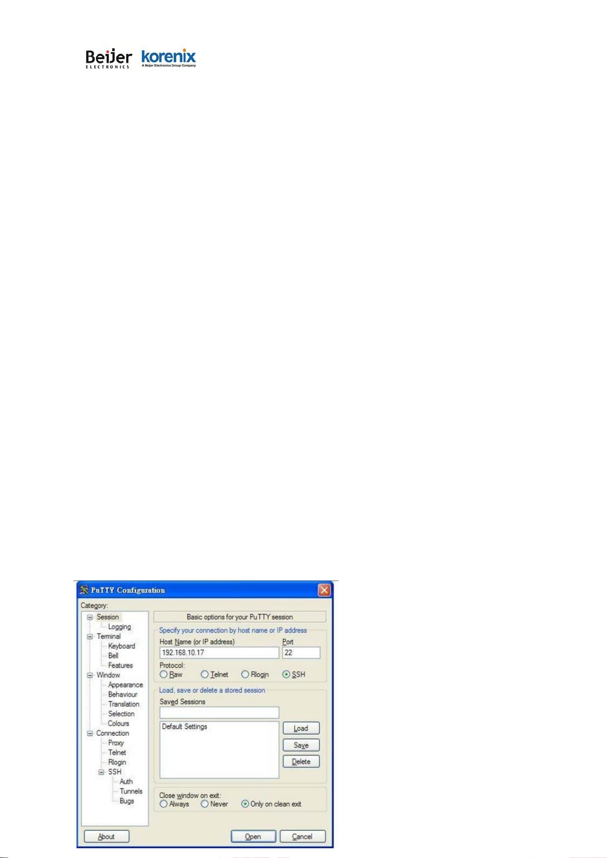
1.
Open SSH Client/PuTTY In the Session configuration, enter the Host Name (IP Address of your
device) and Port number (default = 22).
2.
Choose the “Telnet” protocol. Then click on “Open” to start the Telnet session console.
3.
If you want remote access the CLI securely, choose the “SSH” protocol. Then click on “Open” to
start the SSH session console.
4.
For SSH login: After click on Open, then you can see the cipher information in the popup screen.
Press Yes to accept the Security Alert.
5.
After few seconds, you can see the login screen of the device, the username/password is the
same as the Web GUI (Default: admin/admin).

JetWave 2111/2411 Series User Manual
Page 25
3.6
Discovery Utility – Korenix View Utility
Please download the latest Korenix View Utility from Korenix Web Support page.
The PC with Korenix View Utility can discover the Gateway cross the IP subnet. But, if you want
to do further configuration, the PC must be located in the same subnet with your Gateway. Change
the IP address of your PC or change the IP address of the Gateway.
The chapter 5.3 introduces how to use Korenix View Utility.

JetWave 2111/2411 Series User Manual
Page 26
Chapter 4
Web GUI Configuration
JetWave 2111/2411 Series User Manual
Page 27
Chapter 4 Web GUI Configuration
This chapter describes the Web GUI for Software Configuration.
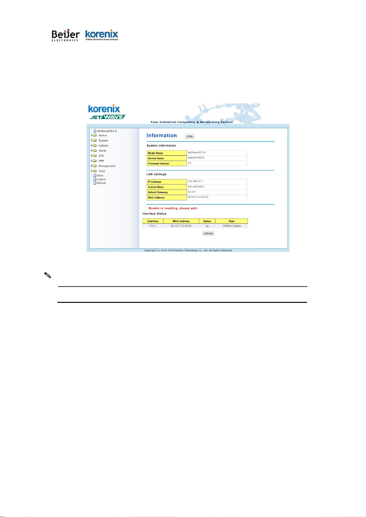
4.1 Status
The Status feature set includes Information, Association List, Network Flow, Bridge Table, ARP
Table and DHCP Client List. The information allows you to see the information of the device.
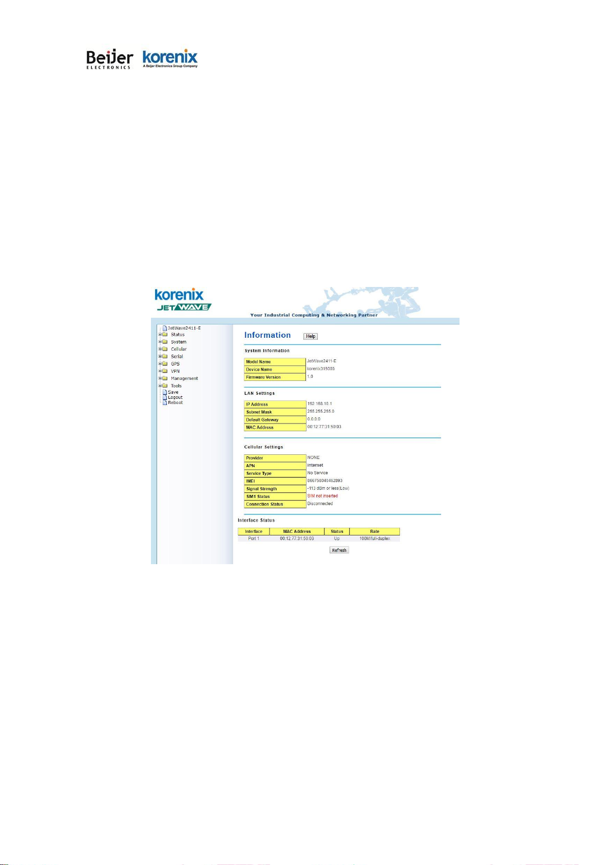
4.1.1
Information
This page shows the current status and some basic setting of the device.
System Information: The Model Name, Device Name, Country/Region you selected and
Firmware version number.
LAN Setting: It shows the IP Address, Subnet Mask, Gateway IP Address and MAC Address of the
LAN interface.
Interface Status: This table shows the Interface Name, MAC Address, Status.
 Loading...