

Korenix JetPort 5601, JetPort 5601f User Manual

Korenix JetPort 5601 / 5601f
Serial Device Server
User’s Manual
Version 1.5
Aug. 2014
www.korenix.com

Korenix JetPort 5601 / 5601f
Serial Device Server
User’s Manual
Copyright Notice
Copyright 2014 Korenix Technology Co., Ltd.
All rights reserved.
Reproduction in any form or by any means without permission is prohibited.

Contents
Chapter 1 Introduction ................................................................................................ 1
Serial to Ethernet Technology Overview ............................................................ 2
Product Features ............................................................................................... 2
Product Specification ......................................................................................... 2
Package Checklist ............................................................................................. 4
Chapter 2 Hardware Installation ................................................................................. 5
Panel and LEDs ................................................................................................. 6
5601 Panel and Interfaces ............................................................................... 6
5601 LED Indicators ......................................................................................... 6
5601f Panel and Interfaces .............................................................................. 7
5601f LED Indicators ........................................................................................ 7
Reset Button ...................................................................................................... 8
Connecting the Power ........................................................................................ 8
Connecting the Network ..................................................................................... 8
Connecting the Serial Device ............................................................................. 8
Chapter 3 Windows Management Tool .................................................................... 11
Software Quick Setup ...................................................................................... 12
Install JetPort Commander ............................................................................. 12
Chapter 4 Web and Telnet Console .......................................................................... 15
Web Console ................................................................................................... 16
Server Configuration ....................................................................................... 16
Port Configuration- Serial Parameter ............................................................. 18
Service Mode- Real/Virtual COM ................................................................... 19
Service Mode- TCP Server ............................................................................. 19
Service Mode- TCP Client .............................................................................. 20
Service Mode- UDP ........................................................................................ 20
Access IP Table .............................................................................................. 21
Event Notification ............................................................................................ 22
Email and SNMP Trap Notification ................................................................. 22
Save / Restart ................................................................................................. 23
SSH Console ................................................................................................... 23
SSH Client ...................................................................................................... 23
Configuration .................................................................................................. 26
Appendix A SNMP MIB II and RS232 Like Support .................................................... 27
Appendix B RS232 Pin Assignment ................................................................ ............ 30


1
1
1
Chapter 1 Introduction
Jetport 5601 series is a smart one RS-232/422/485 to Ethernet serial device server. It includes
JetPort 5601 and 5601f. JetPort 5601 is one-port RS232/422/485 to Redundant Ethernet
Solution. It’s the first serial device server with redundant dual Ethernet ports, the ports can
auto-recovery in less than 200ms. JetPort 5601f is one-port RS232/422/485 to Fiber Ethernet
Solution. 5601f-m supports one Multi-mode fiber port. 5601f-s supports one Single-mode Fiber
port.
JetPort serial device server connects the serial port of devices such as card readers,
measurement devices, or data acquisition terminals, over Ethernet just like locally attached. It
eliminates the limitation of single host and transmission distance of traditional serial
communications by creating access for multiple hosts in Ethernet. The compact size and various
mounting options further create installation flexibility.
This chapter describes:
Serial to Ethernet Technology Overview
Product features
Product specification
Package checklist

2
Network Interface
Ethernet
2* 10/100BaseTX, Redundant Ethernet (JetPort 5601)
100BaseFX Multi-mode (JetPort 5601f-m)
100BaseFX Single-mode (JetPort 5601f-s)
Ethernet Connector
RJ45 (JetPort 5601)
Fiber Connector
100BaseFX: Duplex SC (JetPort 5601f)
Fiber Cable
Multi-mode Fiber: 50/125um or 62.5/125um, max. distance 2KM (JetPort
5601f-m)
Single-mode Fiber: 8/125um, 9/125um or 10/125um, max. distance 30KM
(JetPort 5601f-s)
Fiber Transceiver
JetPort5601f-m, Multi-mode: 2KM max. distance
Wave-length: 1310nm
Min Tx Power:-19dBm
Serial to Ethernet Technology Overview
Korenix JetPort serial device servers provide perfect solution to manage serial devices via
Ethernet in flexible ways, such as TCP server, TCP client, UDP, or Windows Real/Virtual COM.
JetPort creates a transparent gateway for the serial communication to Ethernet. If the control
program uses network standard API, you can choose TCP or UDP as the communication
protocol. If the control program uses COM port, you can install the Windows driver to add
Real/Virtual COM ports.
Product Features
JetPort 5601/5601f has the following features:
Smart one-port RS232/422/485 to Ethernet Solution
Redundant Dual Ethernet Ports, Auto-Recovery in Less Than 200ms (JetPort 5601)
One Multi-mode / Single-mode fiber (JetPort 5601f)
World’s highest serial speed: 460.8kbps
Supports Secured Management by HTTPS and SSH
JetPort Commander, Windows utility for auto discovery, multiple device setting and
monitoring.
Versatile serial operation options: Real/Virtual COM, Serial tunnel, TCP server, TCP client,
UDP
Max. 5 Real/Virtual COM, TCP server, TCP client connections
Event warning by Email, SNMP trap, Syslog and Beeper
Real/Virtual COM driver for Windows NT/2000/XP/2003/7
Product Specification
JetPort 5601 Serial Device Server User’s Manual

Introduction
3
Max Tx Power:-14dBm
Min Rx Sensitivity:-30dBm
Link budget:11dBm
JetPort5601f-s, Single-mode: 30KM max. distance
Wave-length:1310nm
Max Tx Power:-8dBm
Min Tx Power:-15dBm
Min Rx Sensitivity:-34dBm
Link budget:19dBm
Protection
Built-in 1.5 KV magnetic isolation
Protocols
ICMP, IP, TCP, UDP, DHCP, BootP, ARP / RARP, DNS, SNMP MIB II,
HTTPS, SSH
Serial Interface
Interface
RS232, RS422, 2/4-Wire RS485
Connectors
male DB9
Data Rates
110 bps to 460.8 Kbps
Data Bits
5, 6, 7, 8
Parity
odd, even, none
Stop Bits
1, 1.5, 2
RS-232
TxD, RxD, RTS, CTS, DTR, DSR, GND, DCD
RS-422
Tx+,Tx-, Rx+, Rx-,GND
RS-485 (4-wire)
Tx+,Tx-, Rx+, Rx-,GND
RS-485 (2-wire)
Data+, Data-,GND
Flow Control
XON/XOFF, RTS/CTS, DTR/DSR
Serial Line Protection
15KV ESD
Software Utility
Utility
JetPort Commander for Windows 2000/XP/7
Device discovery
Auto IP report
Device setting (run-time change, no rebooting)
Access control list
Group setting
Device monitoring
Serial port monitoring
Log info
Group Firmware update batch
JetPort 5601 Serial Device Server User’s Manual

4
Serial mode
Real/Virtual COM / TCP Server / TCP Client / UDP / Serial Tunnel
TCP Alive Check Timeout
Inactivity Timeout
Delimiter for Data Packing
Force TX Timeout for Data Packing
Multiple link
5 Hosts simultaneous connection: Real/Virtual COM / TCP server / TCP
Client
Real/Virtual COM
Windows 2000/XP/2003/7
Configuration
Web HTTPS console, Telnet SSH console,
JetPort Commander for Windows 2000/XP/7
Power Requirements
Power Input
PWR1: 12~48VDC in 2-pin Terminal Block
PWR2: 9~30VDC in Power Jack with Power Adapter
Power Line protection
1 KV Burst (EFT), EN61000-4-4
0.5 KV Surge, EN61000-4-5
Mechanical
Dimensions
29.6 mm (H) x 96 mm(W) with ears x 99 mm (D)
Regulatory Approvals
FCC Class A, CE Class A
RoHS
Environmental
Operating Temperature
-10 to 70°C (14 to 158°F)
Operating Humidity
5% to 95% (Non-condensing)
Storage Temperature
-20 to 85°C (-4 to 185°F)
Package Checklist
JetPort is shipped with the following items:
Korenix JetPort Serial Device Server
100-240V Power adapter
Mounting kit and 4 screws
4 Foot pads
Documentation and Software CD
Quick Installation Guide
If any of the above items is missing or damaged, please contact your local sales representative.
JetPort 5601 Serial Device Server User’s Manual

5
2
2
Chapter 2 Hardware Installation
JetPort serial device server can be configured by Windows utility, web browser, or Telnet console.
Advanced management features include SNMP support and Email alert. JetPort Commander is a
powerful Windows utility that supports device discovery, group setup, group firmware update, and
monitoring functions.
This chapter introduces how to quick start JetPort
Panel and LED
Reset Button
Connecting the Power
Connecting the Network
Connection the Serial Device
Din-Rail Mounting Installation

6
LED
Color
Indication
PWR 1
Red
On: Power 1 is on and booting up.
Blinking: Indicates an IP conflict, or DHCP or BOOTP server did not
respond properly.
Green
On: Power is on and functioning normally.
Blinking: Located by Administrator’s Location function.
Off
Power is off, or power error condition exists.
PWR 2
Red
On: Power 2 is on and booting up.
Blinking: Indicates an IP conflict, or DHCP or BOOTP server did not
respond properly.
Green
On: Power 2 is on and functioning normally.
Blinking: Located by Administrator’s Location function.
Off
Power is off, or power error condition exists.
Eth 1
Orange
Blinking: 10 Mbps Ethernet connection.
Green
Blinking: 100 Mbps Ethernet connection.
Off
Ethernet cable is disconnected, or has a short.
Eth 2
Orange
Blinking: 10 Mbps Ethernet connection.
Green
Blinking: 100 Mbps Ethernet connection.
Off
Ethernet cable is disconnected, or has a short.
PWR1: Power 1 LED
PWR2: Power 2 LED
Ethernet 1 Link/Act LED
Ethernet 2 Link/Act LED
Serial TX/RX LED
Redundant Dual 10/100M
Ethernet,
Auto-Recovery < 200ms
Auto MDI/MDIX
Built-in 1.5 KV magnetic
isolation
H/W Reset Button
Reset IP address and
configuration to default
Mounting kit
1 RS-232/422/485 port, DB9
15 KV ESD for all signals
110 bps to 460.8 Kbps
Long Distance RS422/485
120ohm Termination
JetPort 5601
Eth1 Eth 2 PWR2 PWR1
PWR 1: Terminal
Block, 12-48VDC
(V+ / V- / GND)
PWR 2: Power
Panel and LEDs
5601 Panel and Interfaces
5601 LED Indicators
There are 5 LEDs in 5601, indicating real-time system status.
JetPort 5601 Serial Device Server User’s Manual
7
Serial
Red
Serial port is receiving data.
Green
Serial port is transmitting data.
Orange
Serial port is continuously transmitting and receiving data.
Off
No data is being transmitted or received through the serial port.
LED
Color
Indication
PWR 1
Red
On: Power 1 is on and booting up.
Blinking: Indicates an IP conflict, or DHCP or BOOTP server did not
respond properly.
Green
On: Power is on and functioning normally.
Blinking: Located by Administrator’s Location function.
Off
Power is off, or power error condition exists.
PWR 2
Red
On: Power 2 is on and booting up.
Blinking: Indicates an IP conflict, or DHCP or BOOTP server did not
respond properly.
Green
On: Power 2 is on and functioning normally.
Blinking: Located by Administrator’s Location function.
Off
Power is off, or power error condition exists.
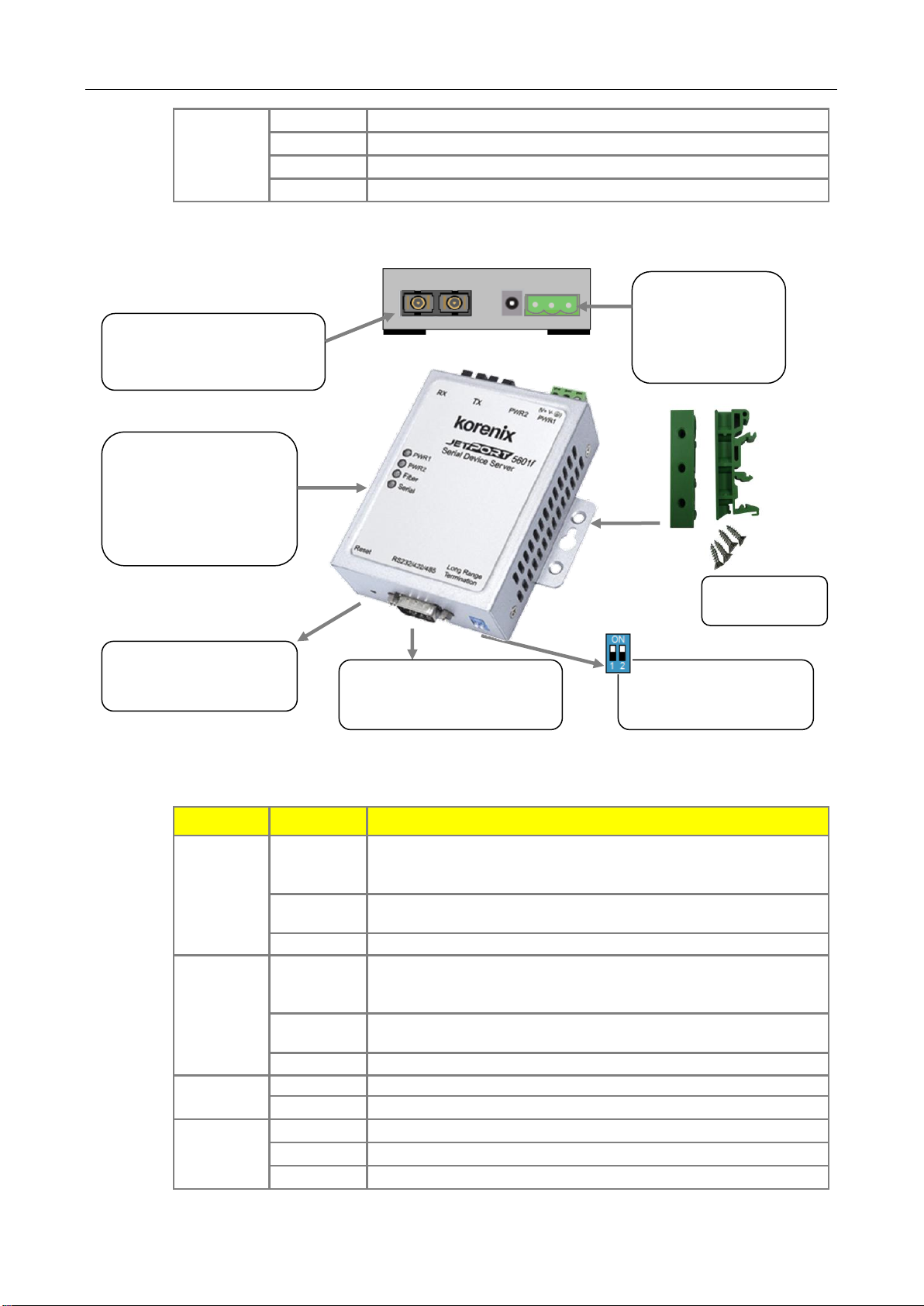
Fiber
Green
Blinking: Fiber connection.
Off
Fiber is disconnected, or has a short.
Serial
Orange
Serial port is receiving data.
Green
Serial port is transmitting data.
Off
No data is being transmitted or received through the serial port.
PWR1: Power 1 LED
PWR2: Power 2 LED
Fiber Link/Act LED
Serial TX/RX LED
PWR 1: Terminal
Block, 12-48VDC
(V+ / V- / GND)
PWR 2: Power
100BaseFX: Duplex SC
Multi-mode or Single-mode
Fiber
H/W Reset Button
Reset IP address and
configuration to default
Mounting kit
1 RS-232/422/485 port, DB9
15 KV ESD for all signals
110 bps to 460.8 Kbps
Long Distance RS422/485
120ohm Termination
JetPort 5601f
RX TX PWR2 PWR1
5601f Panel and Interfaces
Quick Start
5601f LED Indicators
There are 4 LEDs in 5601f, indicating real-time system status.
JetPort 5601 Serial Device Server User’s Manual
 Loading...