

Korenix JetNet 7850G-2XG, JetNet 7850G-2XG-DC48, JetNet 6852G, JetNet 6852G-DC48 Quick Installation Manual
A Beijer Electronics Group Company
JetNet 7850G-2XG/6852G
Industrial 10G SFP+ Layer 3 Managed Ethernet Switch
Quick Installation Guide V1.0
Overview
e JetNet 7850G-2XG and JetNet 6852G are a 19-inch Gigabit Layer 3 Managed Switch,
equipped with 48 10/100/1000 Base-TX ports including 2 x 1/10GbE dual speed SFP+
(JetNet 7850G-2XG) or 4 x 1G SFP (JetNet 6852G) ports delivering maximum throughput
and exibility for high-density and ultra-high-speed connection. In addition to the
100-240VAC power-based JetNet 7850G-2XG and JetNet 6852G model, Korenix provides
the JetNet 7850G-2XG and JetNet 6852G series, which support 48V power inputs and
feature a design with -10~55oC wide operating temperature for severe industrial applications.
Model Name Description
JetNet 7850G-2XG
JetNet 7850G-2XG-DC48
JetNet 6852G
JetNet 6852G-DC48
Industrial 48G+2 x 10G SFP+ Ports Gigabit Layer 3 Managed
Ethernet Switch, 100-240 VAC
Industrial 48G+2 x 10G SFP+ Ports Gigabit Layer 3 Managed
Ethernet Switch, 48VDC
Industrial 48G+4G SFP Ports Gigabit Layer 3 Managed
Ethernet Switch, 100-240VAC
Industrial 48G+4G SFP Ports Gigabit Layer 3 Managed
Ethernet Switch, 48VDC
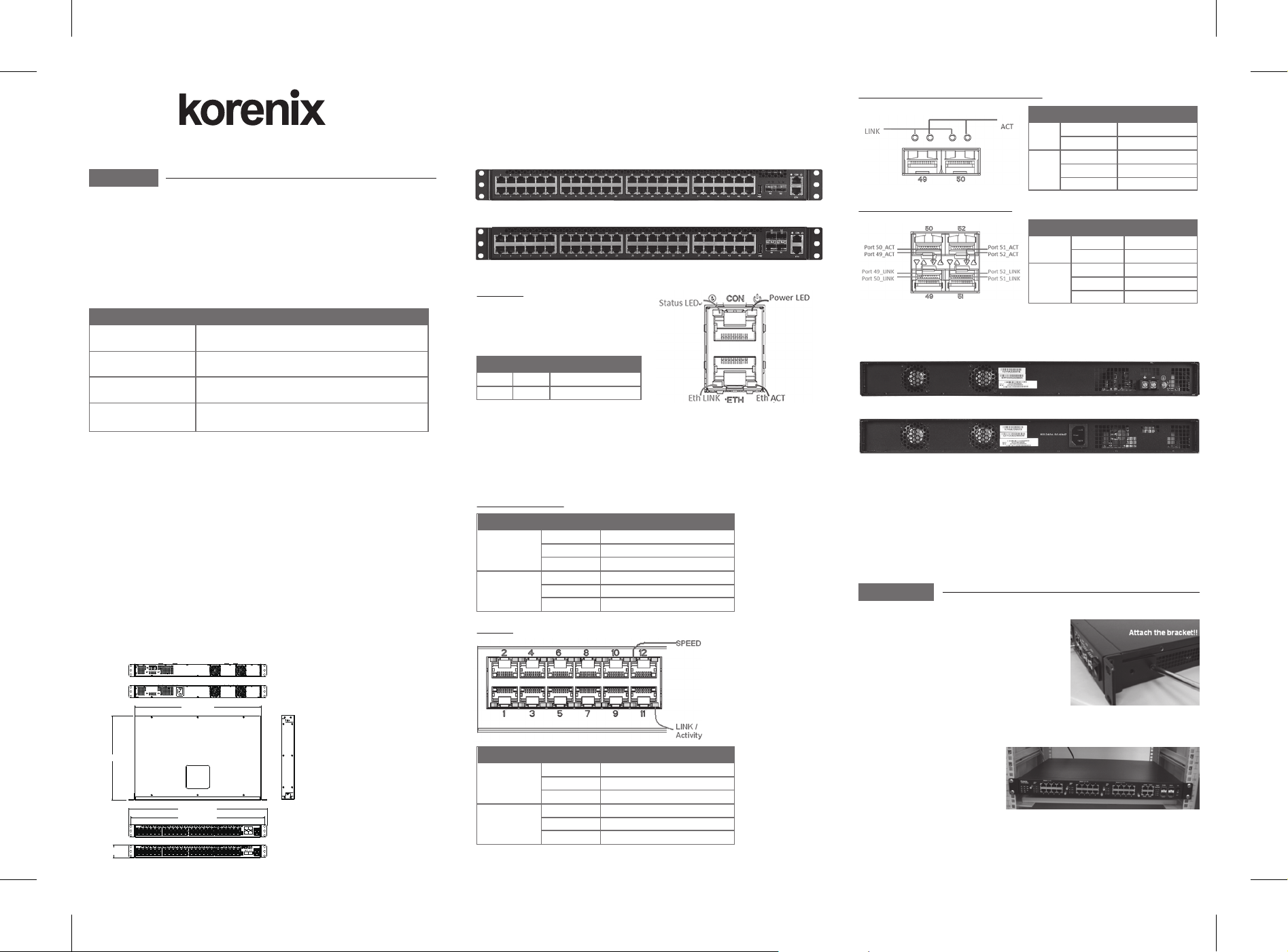
2. Front-Panel Components: e front panel of the Switch consists of 48 Gigabit interfaces ,
2 x 10G ports(JetNet 7850G-2XG) , 4 x 1G SFP ports (JetNet 6852G) , 1 built-in
1000/100/10 RJ-45 Ethernet service ports, an RJ-45 based RS-232 communication port, and
an USB port.
JetNet 7850G-2XG 48 10/100/1000BASE-T with 2 SFP+ 10G interfaces
JetNet 6852G 48 10/100/1000BASE-T with 4 SFP 1G interface
3. LED Indicators
System LED
e Status LED indicator represents status
of the switch. e Power LED indicator
represents power ON or OFF.
LEDLED Function
Color
Orange
Green
System OS is ready
All DC power is ready
Status
Power
10GbE SFP+ Ports for JetNet 7850G-2XG model
LED
LINK
ACT
Color
Green
OFF
Green
Green Blink
OFF
Function
Port Link
Port Disable
Network Link
Network Activity
No Network Link
1GbE SFP Ports for JetNet 6852G model
LED
Port X_
LINK
Port X_
ACT
Color
Green
OFF
Green
Green Blink
OFF
Function
Port Link
Port Disable
Network Link
Network Activity
No Network Link
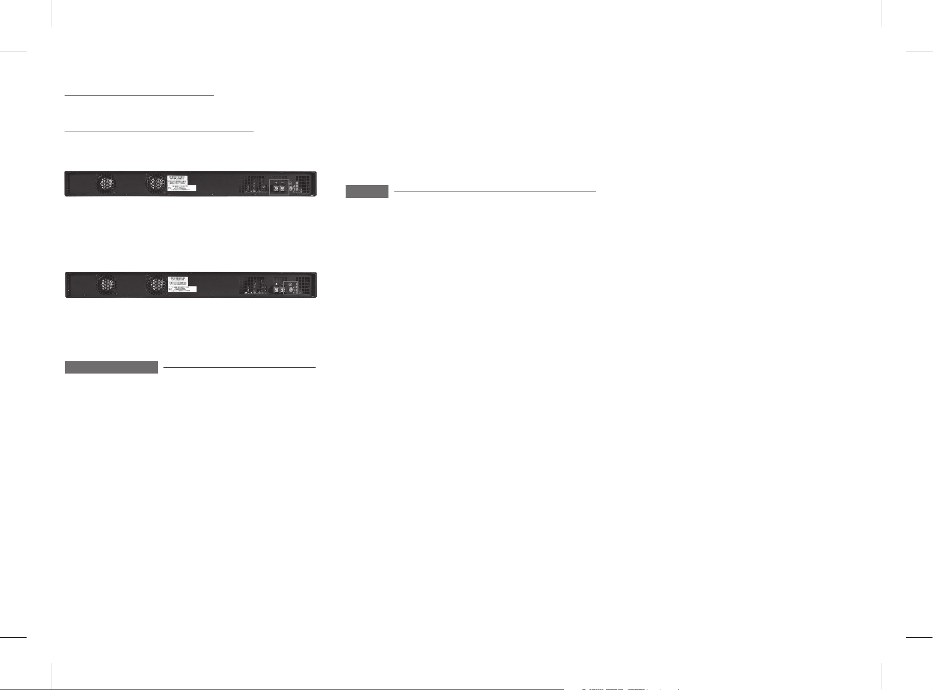
4. Rear Panel Description
e rear panel of the Switch contains AC or DC power connector and 2 Fans.
Rear panel with DC power connector
Rear panel with AC power connector
Package Check List
e Rack Mount Managed Ethernet Switch
Console cable
Rack Mount kit
Power Cord (Depend on Country, JetNet 7850G-2XG-DC48 and JetNet 6852G-DC48
no Power Cord)
QIG
Interface Introduction
1. Dimension: e JetNet 7850G-2XG and JetNet 6852G Industrial Gigabit Layer 3
Managed Switch dimension ( H x W x D) is 44mm x 440mm x 292.1mm.
440(15.74)
292.1(11.5)
481.6(18.96)
464.6(18.29)
44(1.73)
Management Port LED
Function
Port Link at 1000 Mbps
Port Link at 100 Mbps
Port Link at 10 Mbps
Network Link
Network Activity
No Network Link or port disable
Eth LINK
(Speed)
Eth ACT
(Link/Activity)
ColorLED
Orange
Green
Off
Green
Green Blink
Off
Port LED
LEDLED Function
Speed
Link/Activity
Color
Orange
Green
Off
Green
Green Blink
Off
Port Link at 1000 Mbps
Port Link at 100 Mbps
Port Link at 10 Mbps
Network Link
Network Activity
No Network Link or port disable
e DC power range support -48V (-36 ~ -72V) DC input.
e AC power connector is a standard three-pronged connector that supports the power
cord. Plug the female connector of the provided power cord into this socket, and the male
side of the cord into a power outlet. e Switch automatically adjusts its power setting to
any supply voltage in the range from 100 ~ 240 VAC at 50 ~ 60 Hz.
Installation
Mount the Switch to 19’’ rack
1. Attach the brackets to the device by using the
screws provided in the Rack Mount kit.
2. Mount the device in the 19’ rack by using four
rack-mounting screws provided by the rack
manufacturer.
3. When installing multiple switches, mount them
in the rack one below the other.
Note: Check if the rack environment
temperature conforms to the
specied operating temperature
range. Do not place any equipment
on top of the switch and please
properly grounded.
Power the unit and connect to network Cable
1. Wiring Power Inputs
JetNet 7850G-2XG and JetNet 6852G AC Power Input
Connect the attached power cord to the AC power input connector, the available AC power
input is range from 100 ~ 240 VAC at 50 ~ 60 Hz.
JetNet 7850G-2XG-DC48 and JetNet 6852G-DC48 DC Power Input
e suggested power input is -48VDC, the available range is from -36 ~ -72VDC.
Follow below steps to wire JetNet 7850G-2XG-DC48 and JetNet 6852G-DC48 DC power
inputs.
1. Insert positive and negative wires into + and - contacts respectively of the connector.
2. Tighten the wire-clamp screws to prevent DC wires from being loosened.
2. Wiring Earth Ground
To ensure the system will not be damaged by noise or any electrical shock, we suggest you to
make exact connection with JetNet 7850G-2XG-DC48 and JetNet 6852G-DC48 with Earth
Ground.
On the back panel of JetNet 7850G-2XG-DC48 and JetNet 6852G-DC48, there is one earth
ground screw. Loosen the earth ground screw by screw drive; then tighten the screw after earth
ground wire is connected.
Warning: Since the lower hosts under the layer 3 interface can access the switch by default
gateway IP address. Please remember to change the user name and password in your rst
login. Otherwise, the users can easily access the management interface and change the
settings. It obeys the common security concern
2. Command Line Console Interface rough the Serial Port or Telnet
You can also connect a computer or terminal to the serial console port or use Telnet to access
the Switch. e command-line-driven interface provides complete access to all switch
management features. e RS-232 DCE console port is for setting up and managing the
Switch via a connection to a console terminal or PC using a terminal emulation program. e
default baud rate is 115,200, N, 8, 1.
Support
3 Years Warranty
Each of Korenix’s product line is designed, produced, and tested with high industrial
standard. Korenix warrants that the Product(s) shall be free from defects in materials and
workmanship for a period of three (3) years from the date of delivery provided that the
Product was properly installed and used.
is warranty is voided if defects, malfunctions or failures of the warranted Product are
caused by damage resulting from force measure (such as oods, re, etc.), other external forces
such as power disturbances, over spec power input, or incorrect cabling; or the warranted
Product is misused, abused, or operated, altered and repaired in an unauthorized or improper
way.
Device Management
e system may be managed out-of-band through the console port on the rear panel or
in-band using Telnet, a Web Browser, or SNMP.
1. Web-based Management Interface
After you have successfully installed the Switch, you can congure the Switch, monitor the
LED panel, and display statistics graphically using a Web browser, such as Netscape Navigator
(version 6.2 and higher) or Microsoft® Internet Explorer (version 5.0).
e default IP address before conguring is 192.168.10.1. User Name is admin, default
password is admin.
After congured the layer 3 virtual interfaces, you can assign primary IP and second IP
addresses to the interface, this is known as default gateway of the lower hosts. e lower hosts
in each subnet can access the interface by the default gateway IP address.
e default IP address is only available in layer 2 mode, the layer 2 mode means there is no
any congured layer 3 virtual interface. After congured the layer 3 virtual interface, the
default IP address is changed to the assigned primary/second IP address of the interface.
Note: To access the Switch through a Web browser, the computer running the Web browser
must have IP-based network access to the Switch. It is not suggested multiple user’s access to
the web browser. e performance of web display would be aected.
Attention! To avoid system damage caused by sparks, please DO NOT plug in power
connector when power is on.
LED
e product is in compliance with Directive 2002/95/EC and 2011/65/EU of the European
Parliament and of the Council of 27 January 2003 on the restriction of the use of certain
hazardous substances in electrical and electronics equipment(RoHS Directives & RoHS 2.0).
Korenix Customer Service
KoreCARE is Korenix Technology's global service center, where our professional stas are
ready to solve your problems at any time Korenix global service center's e-mail is
KoreCARE@korenix.com.
For more information and documents download please visit our website:
http://www.korenix.com/downloads.htm
LEDLED
Korenix Technology Co., Ltd.
(A Beijer Electronics Group Company)
Tel:+886-2-89111000
Fax:+886-2-29123328
Business service:sales@korenix.com
Customer service:koreCARE@korenix.com
www.korenix.com
CPQ000N7850000
Patent No. (Taiwan):
Granted Invention: I 313547
Granted Invention: I 321415
Granted Invention: I 344766
Granted Invention: I 346480
Granted Invention: I 356616
Granted Invention: I 364684
Granted Invention: I 376118
Granted Invention: I 393317
Granted Invention: I 398066
Granted Invention: I 398125
Utility Model: M 339841
Utility Model: M 339840
 Loading...