

Korenix JetNet 7014G Series, JetNet 7310G Series User Manual

1
Korenix JetNet 7014G Series
Industrial L3 Full Gigabit Managed Ethernet
Switch
User Manual
Version1.0
Jun.,2017
www.korenix.com

2
Korenix JetNet 7014G Series
Industrial L3 Full Gigabit Managed
EthernetSwitch
User’s Manual
Copyright Notice
Copyright 2006-2017 Korenix Technology Co., Ltd.
All rights reserved.
Reproduction in any form or by any means without permission is prohibited.

3
Federal Communications Commission (FCC) Statement
This equipment has been tested and found to comply with the limits for a Class A digital
device, pursuant to Part 15 of the FCC Rules. These limits are designed to provide
reasonable protection against harmful interference when the equipment is operated in a
commercial environment. This equipment generates, uses, and can radiate radio frequency
energy and, if not installed and used in accordance with the instruction manual, may cause
harmful interference to radio communications. Operation of this equipment in a residential
area is likely to cause harmful interference in which case the user will be required to correct
the interference at his expense.
The user is cautioned that changes and modifications made to the equipment without
approval of the manufacturer could void the user’s authority to operate this equipment.

Index
1 Preparation for Management ..................................................................................1
1.1 Preparation for Serial Console ......................................................................... 1
1.2 Preparation for Web Interface .......................................................................... 2
1.3 Preparation for Telnet Console ........................................................................ 4
2 Feature Configuration ............................................................................................7
2.1 Command Line Interface Introduction ............................................................. 8
2.2 Basic Setting .................................................................................................. 13
2.3 Port Configuration ......................................................................................... 35
2.4 Power over Ethernet (JetNet PoE Switch only) ............................................. 46
2.5 Network Redundancy..................................................................................... 50
2.6 VLAN ............................................................................................................ 71
2.7 Traffic Prioritization ....................................................................................... 82
2.8 Multicast Filtering .......................................................................................... 87
2.9 Routing (Layer3 Managed Switch only) ........................................................ 93
2.10 SNMP ......................................................................................................... 115
2.11 Security ...................................................................................................... 119
2.12 Warning ...................................................................................................... 132
2.13 Monitor and Diag ....................................................................................... 139
2.14 Device Front Panel ..................................................................................... 147
2.15 Save ............................................................................................................ 148
2.16 Logout ........................................................................................................ 149
2.17 Reboot ........................................................................................................ 149
3. Appendix ................................................................................................................150
3.1 Product Specification ................................................................................... 150
3.2 Korenix Private MIB .................................................................................... 154
3.3 About Korenix .............................................................................................. 154
3.4 Release History ............................................................................................ 156

1
1 Preparation for Management
JetNet Industrial Managed Switch provides both in-band and out-band configuration
methods. You can configure the switch via RS232 console cable if you don’t attach your
admin PC to your network, or if you lose network connection to your JetNet Managed
Switch. This is so-called out-band management. It wouldn’t be affected by network
performance.
The in-band management means you can remotely manage the switch via the network.
You can choose Telnet or Web-based management. You just need to know the device’s
IP address and you can remotely connect to its embedded HTTP web pages or Telnet
console.
1.1 Preparation for Serial Console
In the unit package, Korenix attached one RJ-45 to RS-232 DB-9 console cable. Please
attach RS-232 DB-9 connector to your PC’s COM port, connect RJ-45 connector to the
Console port of the JetNet Managed Switch. If the serial cable is lost, please follow the
serial console cable PIN assignment to find one..
1. Go to Start -> Program -> Accessories -> Communication -> Hyper Terminal
2. Give a name to the new console connection.
3. Choose the COM name
4. Select correct serial settings. The serial settings of JetNet Managed Switches are
as below: Baud Rate: 9600 / Parity: None / Data Bit: 8 / Stop Bit: 1
5. After connected, you can see Switch login request.
6. Login the switch. The default username is “admin”, password, “admin”.
Boot Loader Rev 1.0.0.2 for JetNet7014G (Jun06 2017 - 10:14:53)
Starting....
Switch login: admin
Password:
JetNet7014G (version 0.0.20-20170606-10:29:12).
Copyright 2006-2017 Korenix Technology Co., Ltd.
Switch>

2
1.2 Preparation for Web Interface
JetNet Managed Switch provides HTTP Web Interface and Secured HTTPS Web
Interface for web management
1.2.1 Web Interface
Korenix web management page is developed by CGI (Common Gateway Interface). It
allows you to use a standard web-browser such as Microsoft Internet Explorer,Mozilla,
and Google Chrome to configure and interrogate the switch from anywhere on the
network.
Before you attempt to use the embedded web interface to manage switch operation,
verify that your JetNet Managed Switch is properly installed on your network and that
every PC on this network can access the switch via the web browser.
1. Verify that your network interface card (NIC) is operational, and that your operating
system supports TCP/IP protocol.
2. Wire DC power to the switch and connect your switch to your computer.
3. Make sure that the switch default IP address is 192.168.10.1.
4. Change your computer IP address to 192.168.10.2 or other IP address which is
located in the 192.168.10.x (Network Mask: 255.255.255.0) subnet.
5. Switch to DOS command mode and ping 192.168.10.1 to verify a normal response
time.
Launch the web browser and Login.
6. Launch the web browser (Internet Explorer or Mozila Firefox) on the PC.
7. Type http://192.168.10.1(or the IP address of the switch). And then press Enter.
8. The login screen will appear next.
9. Key in user name and the password. Default user name and password are both
admin.
<Login screen example – JetNet 7310G>
Click on Enter or Login. Welcome page of the web-based management interface will then
3
appear.
Once you enter the web-based management interface, you can freely change the
JetNet’s IP address to fit your network environment.
Note: The Web UI connection session of JetNet Switch will be logged out automatically
if you don’t give any input after 30 seconds. After logged out, you should re-login and
key in correct username and password again.
1.2.2 Secured Web Interface
Korenix web management page also provides secured management HTTPS login. All
the configuration commands will be secured and will behard for the hackers to sniff the
login password and configuration commands.
Launch the web browser and Login.
1. Launch the web browseron the PC.
2. Type https://192.168.10.1 (or the IP address of the switch). And then press
Enter.
3. The popup screen will appear and request you to trust the secured HTTPS
connection distributed by JetNet first. Press Yes to trust it.
4
4. The login screen will appear.
5. Key in the user name and the password. The default user name and password is
admin.
6. Click on Enter or Login.Welcome page of the web-based management interface
will then appear.
7. Once you enter the web-based management interface, all the commands you see
are the same as what you see by HTTP login.
1.3 Preparation for Telnet Console
1.3.1 Telnet/ SSH (Secure Shell)
You can connect to the device by Telnet and the command lines are the same as what
you see by RS232 console port. Below are the steps to open Telnet connection to the
switch.
1. Go to Start -> Run -> cmd. And then press Enter
2. Type the Telnet 192.168.10.1 (or the IP address of the switch). And then press Enter
Note: the Telnet.exe file is not provided after Window 7. You can download it from
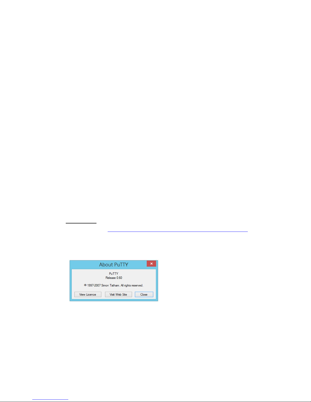
Microsoft web site. Or you can use 3rd Party tool, for example the Putty.
3rd Party tool:
Download PuTTY: http://www.chiark.greenend.org.uk/~sgtatham/putty/download.html
The copyright of PuTTY is belonged to Putty. We don’t have any contract with them.
Please follow the shareware policy of their company.
1. Open SSH Client/PuTTY. In the Session configuration, enter the Host Name (IP
Address of your JetNet Managed Switch) and Port number (default = 22). Choose
the “SSH” protocol. Then click on “Open” to start the SSH session console.Choose
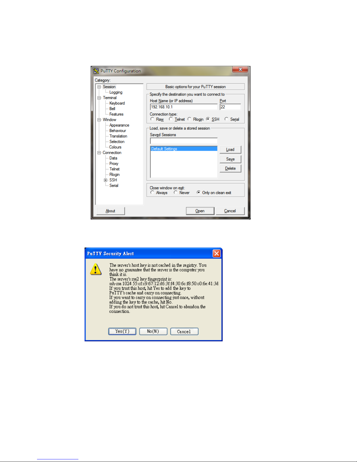
5
the “Telnet” protocol.
2. After click on Open, then you can see the cipher information in the popup screen.
PressYes to accept the Security Alert.
3. After few seconds, the SSH connection to JetNet Managed Switchis opened.
4. Type the Login Name and its Password. The default Login Name and Password are
admin / admin.You can see the screen as the below figure.

6
5. All the commands you see in SSH are the same as the CLI commands you see via
RS232 console. The next chapter will introduce in detail how to use command line to
configure the switch.

7
2 Feature Configuration
This chapter explains how to configure JetNet Managed Switchsoftware features. There
are four ways to access the switch: Serial console, Telnet, Web browser and SNMP.
JetNet Managed Switch provides both in-band and out-band configuration methods. You
can configure the switch via RS232 console cable if you don’t attach your admin PC to
your network, or if you lose the network connection to your JetNet switch. This is so-called
out-band management. It wouldn’t be affected by the network performance.
The in-band management means you can remotely manage the switch via the network.
You can choose Telnet or Web-based management. You just need to know the device’s
IP address. Then you can remotely connect to its embedded HTML web pages or Telnet
console.
Korenix web management page is developed by CGI (Common Gateway Interface. It
allows you to use a standard web-browser such as Microsoft Internet Explorer, or Mozilla,
to configure and interrogate the switch from anywhere on the network.
Following topics are covered in this chapter:
2.1 Command Line Interface (CLI) Introduction
2.2 Basic Setting
2.3 Port Configuration
2.4 Power over Ethernet
2.5 Network Redundancy
2.6 VLAN
2.7 Traffic Prioritization
2.8 Multicast Filtering
2.9 Routing
2.10 SNMP
2.11 Security
2.12 Warning
2.13 Monitor and Diagnostic
2.14 Device Front Panel
2.15 Save
2.16 Logout
2.17 Reboot

8
2.1 Command Line Interface Introduction
The Command Line Interface (CLI) is the user interface to the switch’s embedded
software system. You can view the system information, show the status, configure the
switch and receive a response back from the system by keying in a command.
There are some different command modes. Each command mode has its own access
ability, available command lines and uses different command lines to enter and exit.
These modes are User EXEC, Privileged EXEC, Global Configuration, (Port/VLAN)
Interface Configuration modes.
User EXEC mode: As long as you login the switch by CLI. You are in the User EXEC
mode. You can ping, telnet remote device, and show some basic information.
Typeenable to enter next mode, exit to logout.?to see the command list
Privileged EXEC mode: Press enable in the User EXEC mode, then you can enter the
Privileged EXEC mode. In this mode, the system allows you to view current configuration,
reset default, reload switch, show system information, save configuration…and enter the
global configuration mode.
Type configure terminal to enter next mode, exit to leave. ?to see the command list
Switch#
archive manage archive files
clear Reset functions
clock Configure time-of-day clock
configure Configuration from vty interface
copy Copy from one file to another
debug Debugging functions (see also 'undebug')
dir Display a list of files
disable Turn off privileged mode command
dot1x IEEE 802.1x standard access security control
end End current mode and change to enable mode
exit Exit current mode and down to previous mode
list Print command list
mac MAC interface commands
no Negate a command or set its defaults
pager Terminal pager
ping Send echo messages
quit Exit current mode and down to previous mode
reboot Reboot system
reload copy a default-config file to replace the current one
show Show running system information
telnet Open a telnet connection
terminal Set terminal line parameters
traceroute Trace route to destination
Switch#
enableTurn on privileged mode command
exit Exit current mode and down to previous mode
listPrint command list
ping Send echo messages
quit Exit current mode and down to previous mode
show Show running system information
telnet Open a telnet connection
traceroute Trace route to destination

9
write Write running configuration to memory, network, or terminal
Global Configuration Mode: Press configure terminal in privileged EXEC mode. You
can thenenter global configuration mode. In global configuration mode, you can configure
all the features that the system provides you.
Type interface IFNAME/VLAN to enter interface configuration mode, exit to leave. ?to
see the command list.
Available command lists of global configuration mode.
Switch# configure terminal
Switch(config)#
access-list Add an access list entry
administrator Administrator account setting
auth Authentication
clock Configure time-of-day clock
default Set a command to its defaults
dot1x IEEE 802.1x standard access security control
end End current mode and change to enable mode
erps Ethernet Ring Protection Switching (ITU-T G.8032)
ethernet-ip Ethernet/IP Protocol
exit Exit current mode and down to previous mode
gmrp GMRP protocol
gvrp GARP VLAN Registration Protocol
hostname Set system's network name
interface Select an interface to configure
ip Global IP configuration subcommands
ipv6 IP information
lacp Link Aggregation Control Protocollist
list Print command list
lldp Link Layer Discovery Protocol
log Logging control
loop-protect Ethernet loop protection
mac Global MAC configuration subcommands
mac-address-table mac address table
mirror Port mirroring
modbus Modbus TCP Slave
multiple-super-ring Configure Multiple Super Ring
nameserver DNS Server
no Negate a command or set its defaults
ntp Configure NTP
poe Configure power over ethernet
ptp IEEE1588 PTPv2
qos Quality of Service (QoS)
relay relay output type information
router Enable a routing process
service System service
sfp Small form-factor pluggable
smtp-server SMTP server configuration
snmp-server the SNMP server
spanning-tree the spanning tree algorithm
trunk Trunk group configuration
vlan Virtual LAN
warning-event Warning event selection
write-config Specify config files to write to

10
(Port) Interface Configuration: Press interface IFNAME in global configuration mode.
You can thenenter interface configuration mode. In this mode, you can configure port
settings.
The port interface name for gigabit Ethernet port 1 is gi1..gigabit Ethernet port 10 is gi10.
Type interface name accordingly when you want to enter certain interface configuration
mode.
Type exit to leave.
Type ?to see the command list
Available command lists of the global configuration mode.
Switch(config)# interface gi
Switch(config-if)#
acceptable Configures the 802.1Q acceptable frame types of a port.
auto-negotiation Enables auto-negotiation state of a given port
description Interface specific description
dot1x IEEE 802.1x standard access security control
duplex Specifies the duplex mode of operation for a port
end End current mode and change to enable mode
ethertype Ethertype
exit Exit current mode and down to previous mode
flowcontrol Sets the flow-control value for an interface
garp General Attribute Registration Protocol
ingress 802.1Q ingress filtering features
ip Interface Internet Protocol config commands
lacp Link Aggregation Control Protocol
list Print command list
loopback Specifies the loopback mode of operation for a port
mac MAC interface commands
media-type Specify media type
mtu Specifies the MTU on a port.
no Negate a command or set its defaults
qos Quality of Service (QoS)
quit Exit current mode and down to previous mode
rate-limit Rate limit configuration
sfp Small form-factor pluggable
shutdown Shutdown the selected interface
spanning-tree the spanning-tree protocol
speed Specifies the speed of a Fast Ethernet port or a
Gigabit
Ethernet port.
storm-control Enables packets flooding rate limiting features
switchport Set switching mode characteristics
(VLAN) Interface Configuration: Press interface VLANVLAN-ID in global configuration
mode. You can then enter VLAN interface configuration mode. In this mode, you can
configure the settings for the specific VLAN.
The VLAN interface name of VLAN 1 is VLAN 1, VLAN 2 is VLAN 2…
Type exit to leave the mode. Type ?to see the available command list.

11
The command lists of the VLAN interface configuration mode.
Switch(config)# interface vlan1
Switch(config-if)#
description Interface specific description
end End current mode and change to enable mode
exit Exit current mode and down to previous mode
ip Interface Internet Protocol config commands
ipv6 Interface Internet Protocol config commands
list Print command list
no Negate a command or set its defaults
quit Exit current mode and down to previous mode
shutdown Shutdown the selected interface
Summary of the 5 command modes:
Command Mode
Main Function
Enter and Exit Method
Prompt
User EXEC
This is the first level of
access.
User can ping, telnet
remote device, and show
some basic information
Enter: Login successfully
Exit: exit to logout.
Next mode: Type enable to enter
privileged EXEC mode.
Switch>
Privileged EXEC
In this mode, the system
allows you to view current
configuration, reset default,
reload switch, show system
information, save
configuration…and enter
global configuration mode.
Enter: Type enable in User EXEC
mode.
Exec: Type disable to exit to user
EXEC mode.
Type exit to logout
Next Mode: Typeconfigure
terminalto enter global
configurationcommand.
Switch#
Global
configuration
In global configuration
mode, you can configure all
the features that the
system provides you
Enter: Type configure terminal in
privileged EXEC mode
Exit: Typeexit or end or press
Ctrl-Zto exit.
Next mode: Type interface
IFNAME/ VLAN VID to enter
interface configuration mode
Switch(config)#
Port
Interface
configuration
In this mode, you can
configure port related
settings.
Enter: Type interface IFNAME in
global configuration mode.
Exit: Type exit or Ctrl+Z to global
configuration mode. Type end to
privileged EXEC mode.
Switch(config-if)#
12
VLAN Interface
Configuration
In this mode, you can
configure settings for
specific VLAN.
Enter: Type interface VLAN VID
in global configuration mode.
Exit: Type exit or Ctrl+Z to global
configuration mode. Type end to
privileged EXEC mode.
Switch(config-vlan)#
Here are some useful commands for you to see these available commands. Save your
time in typing and avoid typing error.
To see all the available commands in this mode. It helps you to see the next command
you can/should type as well.
(Character)? To see all the available commands starts from this character.
Tab Thistab key helps you to input the command quicker. If there is only one available
command in the next, clickingon tab key can help to finish typing soon.
Ctrl+C To stop executing the unfinished command.
Ctrl+S To lock the screen of the terminal. You can’t input any command.
Ctrl+Q To unlock the screen which is locked by Ctrl+S.
Ctrl+Z To exit configuration mode.
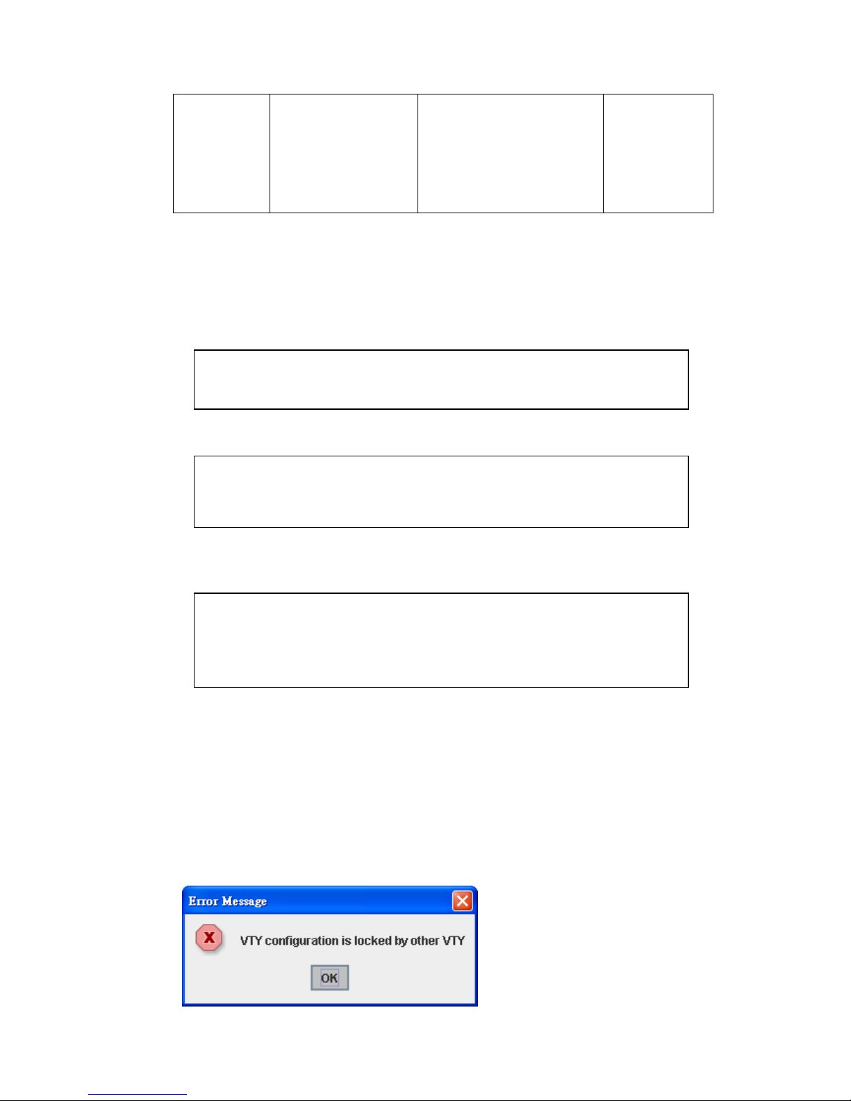
Alert message when multiple users want to configure the switch. If the administrator is in
configuration mode, then the Web users can’t change the settings. JetNet Managed
Switch allows only one administrator to configure the switch at a time.
Switch(config)# a?
access-list Add an access list entry
administrator Administrator account setting
auth Authentication
Switch# con (tab) (tab)
Switch# configure terminal
Switch(config)# ac (tab)
Switch(config)# access-list
Switch(config)# interface (?)
IFNAME Interface's name
vlan Select a vlan to configure
13
2.2 Basic Setting
The Basic Setting group provides you to configure switch information, IP address, User
name/Password of the system. It also allows you to do firmware upgrade, backup and
restore configuration, reload factory default, and reboot the system.
Following commands are included in this group:
2.2.1 Switch Setting
2.2.2 Admin Password
2.2.3 IP Configuration
2.2.4 Time Setting
2.2.5 Jumbo Frame
2.2.6 DHCP Server
2.2.7 Backup and Restore
2.2.8 Firmware Upgrade
2.2.9 LoadDefault
2.2.10 CLI Commands for Basic Setting
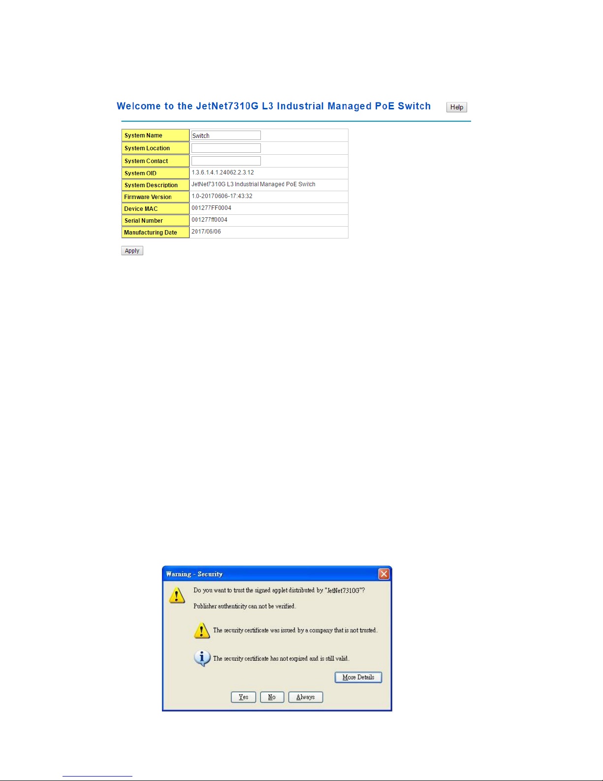
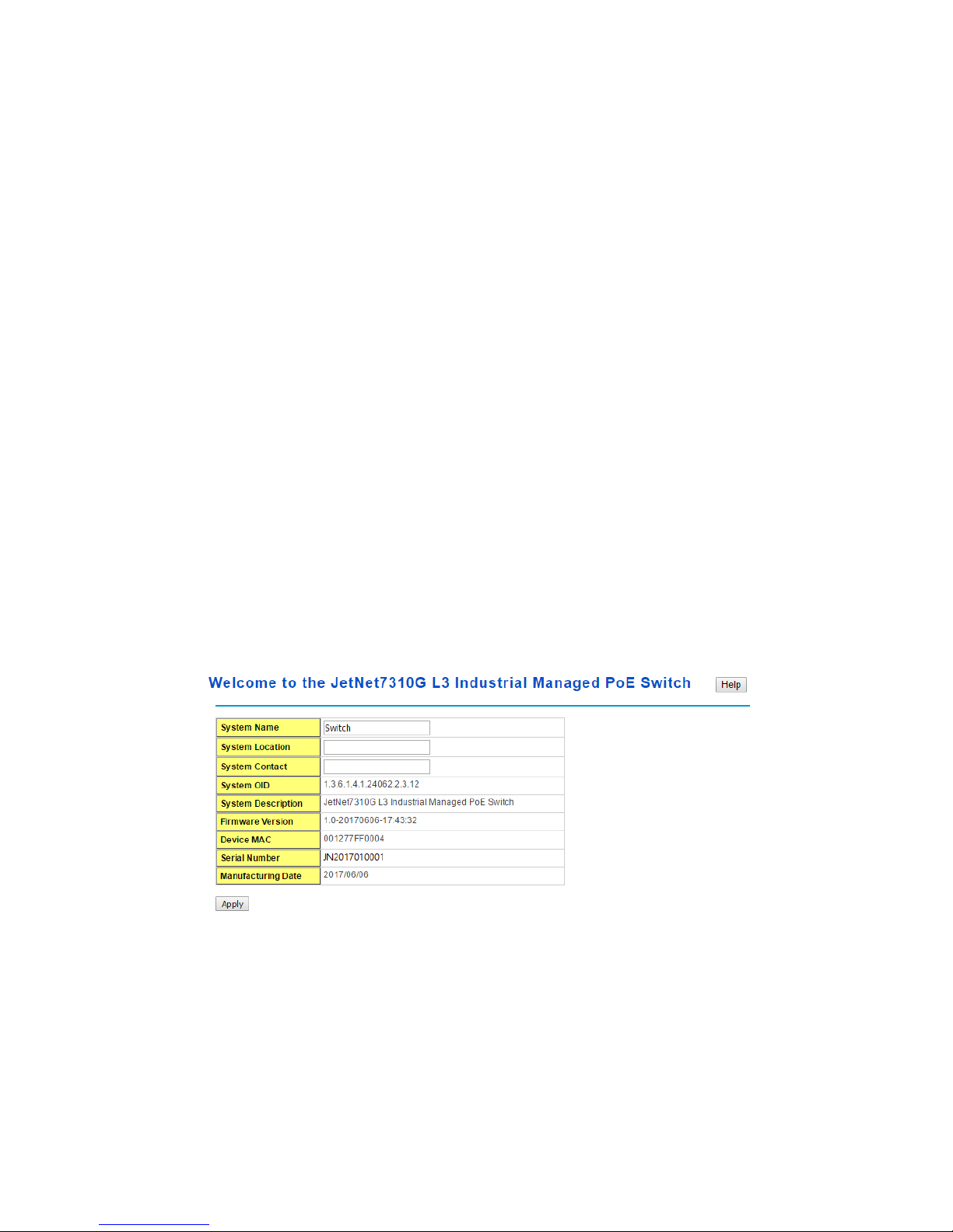
2.2.1 Switch Setting
You can assign System name, Location, Contact and view system information.
< Web UI Example of the Switch Setting>
System Name: You can assign a name to the device. The available characters you can
input is 64. After you configure the name, CLI system will select the first 12 characters as
the name in CLI system.
System Location: You can specify the switch’s physical location here. The available
characters you can input are 64.
System Contact: You can specify contact people here. You can type the name, mail
address or other information of the administrator.The available characters you can input
14
are 64.
System OID: The SNMP object ID of the switch. You can follow the path to find its private
MIB in MIB browser. (Note: When you attempt to view private MIB, you should compile
private MIB files into your MIB browser first.)
System Description: The name of this managed product.
Firmware Version: Display the firmware versioninstalled in this device.
MAC Address: Display unique hardware address (MAC address) assigned by the
manufacturer.
Serial Number: The serial number of this managed product.
Manufacturing Date: The manufacturing date of this managed product.
Once you finish the configuration, click on Apply to apply your settings.
Note: Always remember to select Save to save your settings. Otherwise, the settings you
made will be lost when the switch is powered off.
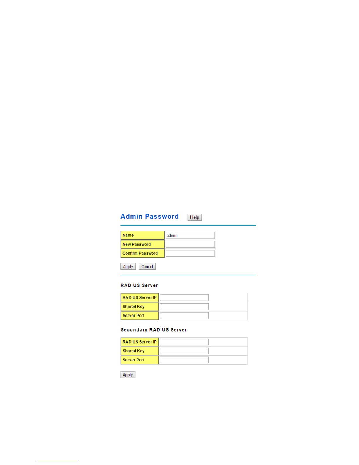
2.2.2 Admin Password
You can change the user name and the password here to enhance security.
<Web UI of the Admin Password>
Name: You can key in new user name here. The default setting is admin.
New Password: You can key in new password here. The default setting is admin.
15
Confirm Password: You need to type the new password again to confirm it.
Once you finish configuring the settings, click on Apply to apply your configuration.
RADIUS Server/ Secondary RADIUS Server
RADIUS Server: The IP address of Radius server
Shared Key: It is the password for communicate between switch and Radius Server.
Server Port: UDP port of Radius server.
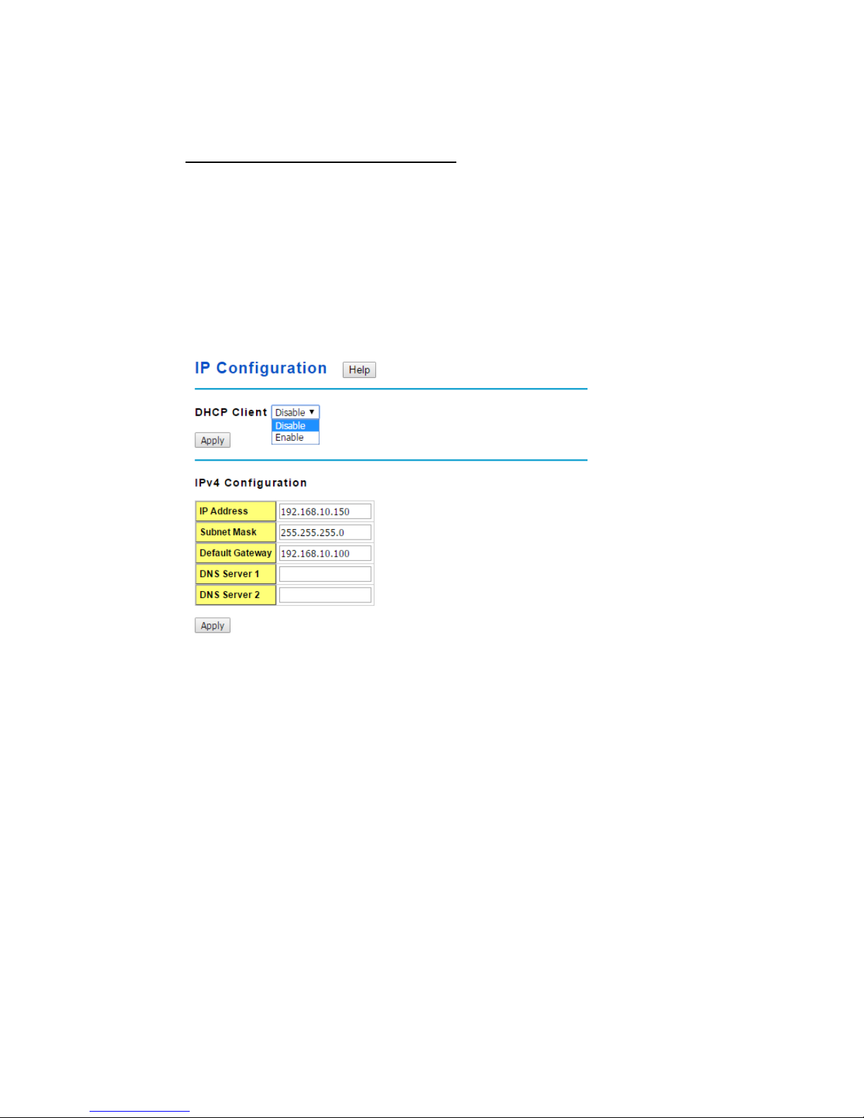
2.2.3 IP Configuration
This function allows users to configure the switch’s IP address settings.
DHCP Client: You can select to Enable or Disable DHCP Client function. When DHCP
Client function is enabled, an IP address will be assigned to the switch from the network’s
DHCP server. In this mode, the default IP address will therefore be replaced by the one
assigned by DHCP server. If DHCP Client is disabled, then the IP address that you
specified will be used instead.
IP Address: You can assign the IP address reserved by your network for your JetNet
switch. If DHCP Client function is enabled, you don’t need to assign an IP address to the
JetNet switch, as it will be overwritten by DHCP server and shown here. The default IP is
192.168.10.1.
Subnet Mask: You can assign the subnet mask for the IP address here. If DHCP Client
function is enabled, you don’t need to assign the subnet mask. The default Subnet Mask
is 255.255.255.0.(Note: In the CLI, we use the enabled bit of the subnet mask to
represent the number displayed in web UI. For example, 8 stands for 255.0.0.0; 16 stands
for 255.255.0.0; 24 stands for 255.255.255.0.)
Default Gateway: You can assign the gateway for the switch here. The default gateway
is 192.168.10.254(Note: In CLI, we use 0.0.0.0/0 to represent for the default gateway.)
DNS Server 1/ DNS Server 2: You can assign the DNS for the switch here.
Once you finish configuring the settings, click on Apply to apply your configuration.
16
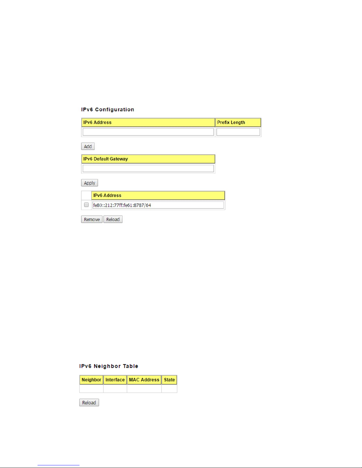
IPv6 Configuration –An IPv6 address is represented as eight groups of four hexadecimal
digits, each group representing 16 bits (two octets). The groups are separated by colons
(:), and the length of IPv6 address is 128bits.
An example of an IPv6 address is: 2001:0db8:85a3:0000:0000:8a2e:0370:7334.
The Leading zeroes in a group may be omitted. Thus, for example,a IPv6 link-local
address may be written as: fe80::212:77ff:fe60:ca90.
IPv6 Address: typing new IPv6 address in this field.
Prefix Length: The size of subnet or network, and it equivalent to the subnetmask, but
writtenin different.The default subnet mask length is 64bits, and written in decimal value -
64.
Add: after add new IPv6 address and prefix, don’t forget click icon-“Add”to apply new
address to system.
Remove:Select existed IPv6 address and click icon-“Remove”to delete IP address.
Reload:Refresh and reload IPv6 address listing.
IPv6 Default Gateway: assign the IPv6 default gateway here.Type IPv6 address of the
gateway then click “Apply”. (Note: In CLI, we user ::/0 to represent for the IPv6 default
gateway.)
17
IPv6Neighbor Table: shows the IPv6 address of neighbor, connected interface, MAC
address of remote IPv6 device, and current state of neighbor device.
The system will update IPv6 Neighbor Table automatically, and user also can click the
icon “Reload” to refresh the table.
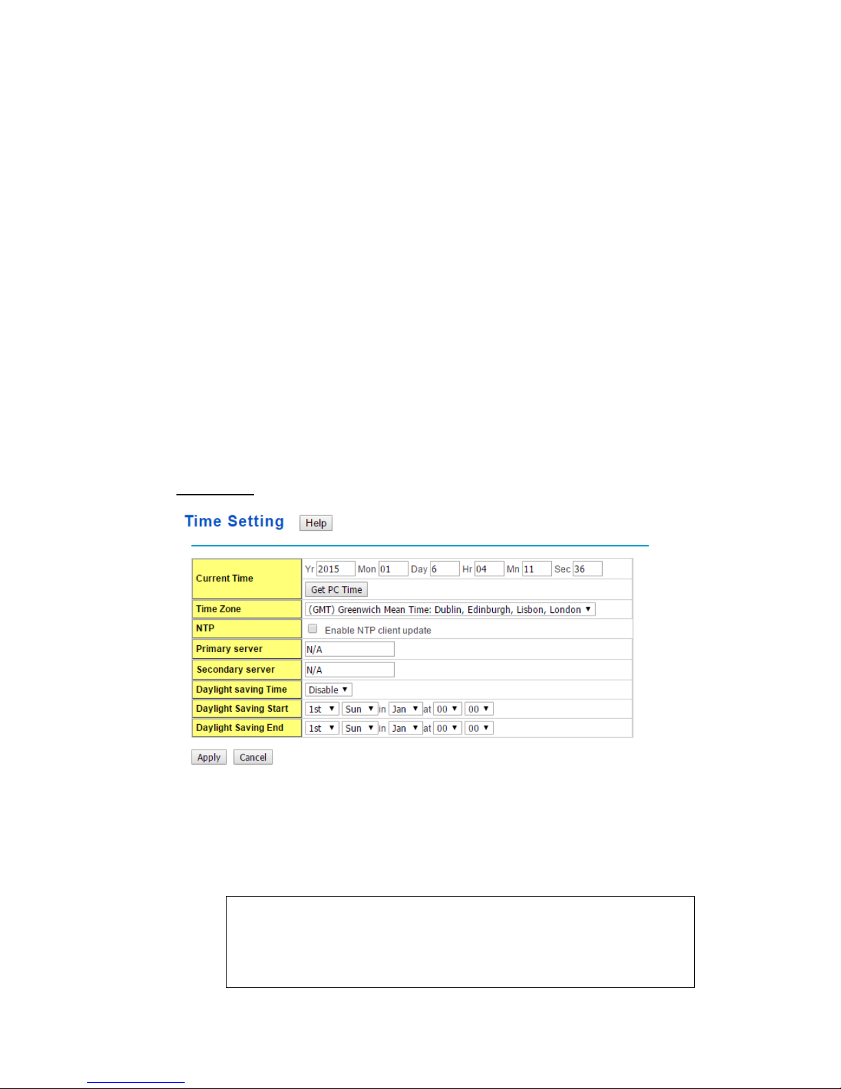
2.2.4 Time Setting
Time Setting source allow user to set the time manually or through NTP server. Network
Time Protocol (NTP) is used to synchronize computer clocks on the internet. You can
configure NTP settings here to synchronize the clocks of several switches on the network.
Below figure is similar as JetNet Switch.
The IEEE1588 PTP (Precision Time Protocol) supports very precise time synchronization
in an Ethernet network. There are two clocks, Master and Slave. The master device
periodically launches an exchange of messages with slave devices to help each slave clock
re-compute the offset between its clock and the master's clock.
Note: Please enable one synchronization protocol (PTP/NTP) only.
Time Setting
User canchange time as user wants. User alsocan click the button “Get PC Time” to get
PC’s time setting for switch. After click the “Get PC Time” and apply the setting, the System
time display the same time as your PC’s time.
Time-zone: Select the time zone where the switch is located. Following table lists the
time zones for different locations for your reference. The default time zone is GMT
Greenwich Mean Time.
Switch(config)# clock timezone
01 (GMT-12:00) Eniwetok, Kwajalein
02 (GMT-11:00) Midway Island, Samoa
03 (GMT-10:00) Hawaii
04 (GMT-09:00) Alaska

18
05 (GMT-08:00) Pacific Time (US & Canada) , Tijuana
06 (GMT-07:00) Arizona
07 (GMT-07:00) Mountain Time (US & Canada)
08 (GMT-06:00) Central America
09 (GMT-06:00) Central Time (US & Canada)
10 (GMT-06:00) Mexico City
11 (GMT-06:00) Saskatchewan
12 (GMT-05:00) Bogota, Lima, Quito
13 (GMT-05:00) Eastern Time (US & Canada)
14 (GMT-05:00) Indiana (East)
15 (GMT-04:00) Atlantic Time (Canada)
16 (GMT-04:00) Caracas, La Paz
17 (GMT-04:00) Santiago
18 (GMT-03:00) NewFoundland
19 (GMT-03:00) Brasilia
20 (GMT-03:00) Buenos Aires, Georgetown
21 (GMT-03:00) Greenland
22 (GMT-02:00) Mid-Atlantic
23 (GMT-01:00) Azores
24 (GMT-01:00) Cape Verde Is.
25 (GMT) Casablanca, Monrovia
26 (GMT) Greenwich Mean Time: Dublin, Edinburgh, Lisbon, London
27 (GMT+01:00) Amsterdam, Berlin, Bern, Rome, Stockholm, Vienna
28 (GMT+01:00) Belgrade, Bratislava, Budapest, Ljubljana, Prague
29 (GMT+01:00) Brussels, Copenhagen, Madrid, Paris
30 (GMT+01:00) Sarajevo, Skopje, Sofija, Vilnius, Warsaw, Zagreb
31 (GMT+01:00) West Central Africa
32 (GMT+02:00) Athens, Istanbul, Minsk
33 (GMT+02:00) Bucharest
34 (GMT+02:00) Cairo
35 (GMT+02:00) Harare, Pretoria
36 (GMT+02:00) Helsinki, Riga, Tallinn
37 (GMT+02:00) Jerusalem
38 (GMT+03:00) Baghdad
39 (GMT+03:00) Kuwait, Riyadh
40 (GMT+03:00) Moscow, St. Petersburg, Volgograd
41 (GMT+03:00) Nairobi
42 (GMT+03:30) Tehran
43 (GMT+04:00) Abu Dhabi, Muscat
44 (GMT+04:00) Baku, Tbilisi, Yerevan
45 (GMT+04:30) Kabul
46 (GMT+05:00) Ekaterinburg
47 (GMT+05:00) Islamabad, Karachi, Tashkent
48 (GMT+05:30) Calcutta, Chennai, Mumbai, New Delhi
49 (GMT+05:45) Kathmandu
50 (GMT+06:00) Almaty, Novosibirsk
51 (GMT+06:00) Astana, Dhaka
52 (GMT+06:00) Sri Jayawardenepura
53 (GMT+06:30) Rangoon
19
54 (GMT+07:00) Bangkok, Hanoi, Jakarta
55 (GMT+07:00) Krasnoyarsk
56 (GMT+08:00) Beijing, Chongqing, Hong Kong, Urumqi
57 (GMT+08:00) Irkutsk, Ulaan Bataar
58 (GMT+08:00) Kuala Lumpur, Singapore
59 (GMT+08:00) Perth
60 (GMT+08:00) Taipei
61 (GMT+09:00) Osaka, Sapporo, Tokyo
62 (GMT+09:00) Seoul
63 (GMT+09:00) Yakutsk
64 (GMT+09:30) Adelaide
65 (GMT+09:30) Darwin
66 (GMT+10:00) Brisbane
67 (GMT+10:00) Canberra, Melbourne, Sydney
68 (GMT+10:00) Guam, Port Moresby
69 (GMT+10:00) Hobart
70 (GMT+10:00) Vladivostok
71 (GMT+11:00) Magadan, Solomon Is., New Caledonia
72 (GMT+12:00) Aukland, Wellington
73 (GMT+12:00) Fiji, Kamchatka, Marshall Is.
74 (GMT+13:00) Nuku'alofa
NTP client: Select the Time Setting Source to NTP client can let device enable the
NTPclient service. NTP client will be automatically enabled if you change Time source to
NTPClient. The system will send request packet to acquire current time from the NTP
serveryou assigned.
Daylight Saving Time: click the check box to enable the Daylight Saving Function as the
setting of start and end time or disable it.
Daylight Saving Start and Daylight Saving End:the time setting allows user to selects
the week that monthly basis, and sets the End and Start time individually.
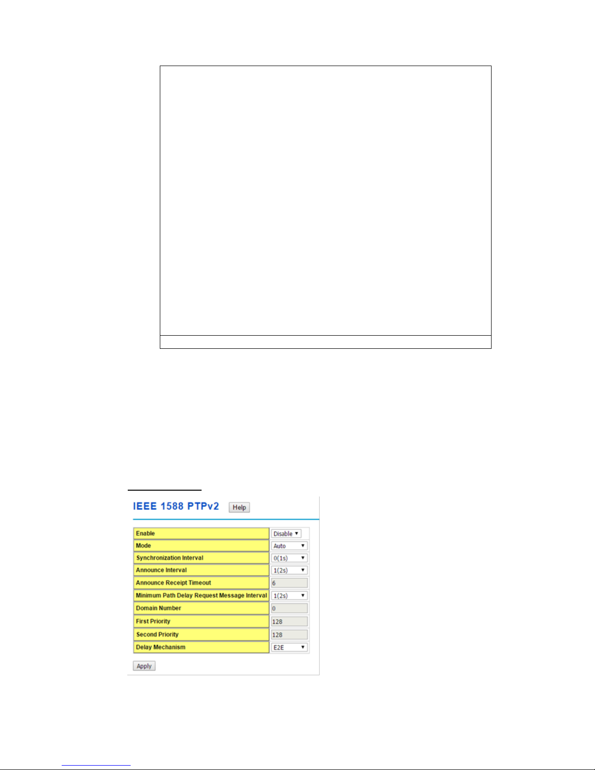
IEEE 1588 PTPv2
To enable IEEE 1588, select Enable in PTP Status and choose Auto, Master or Slave Mode.

20
After time synchronized, the system time will display the correct time of the PTP server.
Mode:
Auto mode: the switch performs PTP Master and slave mode.
Master mode: switch performs PTP Master only.
Slave mode: switch performs PTP slave only.
Synchronization Interval:
Select items: -3(128ms) -2(256ms) -1(512ms) 0(1s) 1(2s) 2(4s) 3(8s) 4(16s)
Announce Interval:
Select items:0(1s) 1(2s) 2(4s) 3(8s) 4(16s)
AnnounceReceipt Timeout:
Select items:<2-10>
Minimum Path Delay Request Message Interval:
Select items: -1(512ms) 0(1s) 1(2s) 2(4s) 3(8s) 4(16s)
Domain Number:
Select items:<0-3>
First Priority:
First priority Select items:<0-255>
Second Priority:
Second priority Select items:<0-255>
Delay Mechanism:
E2E: End-to-End
PTP: Peer-to-Peer
Once you finish your configuration, click on Apply to apply your configuration.
2.2.5 Jumbo Frame
The switchallows you configure the size of the MTU, Maximum Transmission Unit. The
default value is 1,518bytes. The maximum Jumbo Frame size is 9,216 bytes. You can freely
change the available packet size.
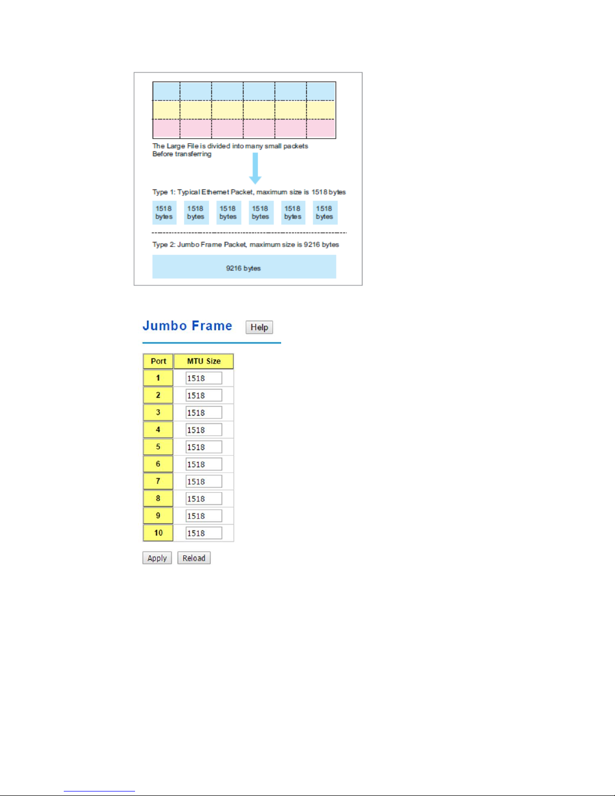
21
Once you finish your configuration, click on Apply to apply your configuration.
2.2.6 DHCP Server
You can select to Enable or Disable DHCP Server function. The Managed Switch will
assign a new IP address to link partners.
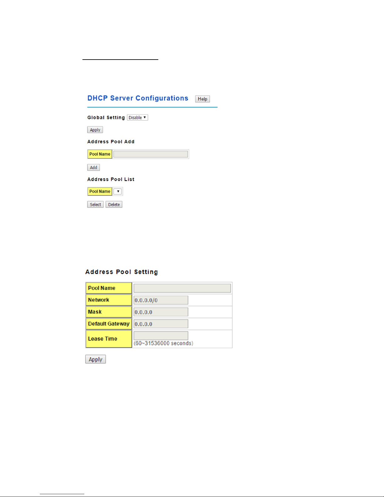
22
DHCP Server configuration
After selecting to enable DHCP Server function, type in the Network IP address for the
DHCP server IP pool, Subnet Mask, Default Gateway address and Lease Time for client.
Once you have finished the configuration, click Apply to activate the new configuration
Global Setting: You can enable or disable the local DHCP server
Address Pool Add: Add a address pool setting into local DHCP server.
Address Pool List: You can select a address pool setting here. Click the Select button to
change address pool. Click the Delete button to delete the address pool.
Pool Name: The address pool name.
Network: The network that you want the DHCP server to distribute.
Mask: The subnet mask of the network.
Default Gateway: The default gateway IP address that you want the DHCP server to
distribute.
Lease Time: The time in seconds a DHCP lease is valid for.
23
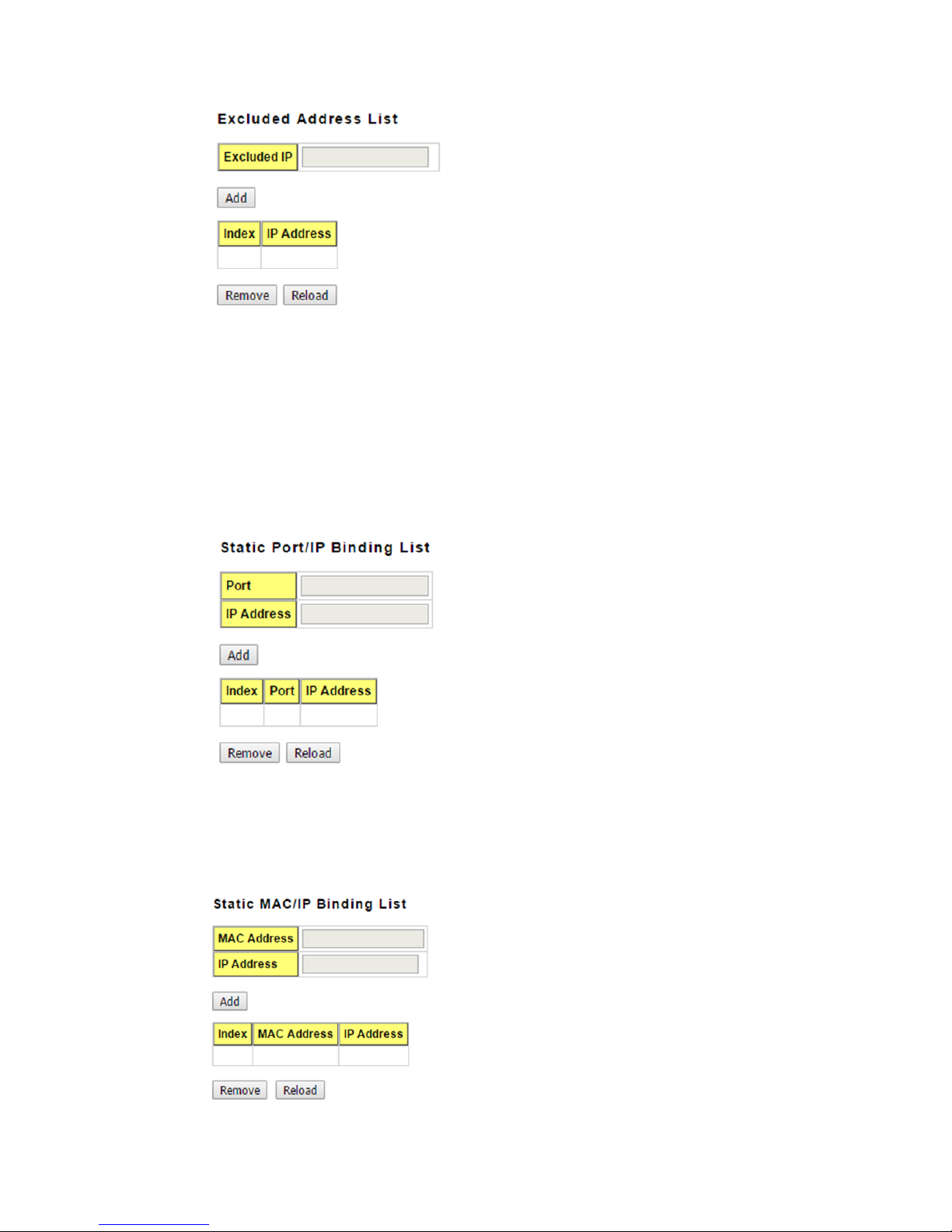
This section allows you to exclude IP addresses within the network range from being
assigned to devices.
Excluded IP: An IP address you want to exclude from being leased.The Excluded
Address List table contains the following fields:
Index: The indexes of the excluded IP addresses.
IP Address: The excluded IP addresses.
.Click the Remove button to remove the selected IP address(es) or click the Reloadbutton
to reload the selected IP address(es).
This feature allows you to bind an IP address to a specific port. A device connected to this
port will be assigned the chosen IP address. Click the Add button to add a static port
binding.
Port: The port you want to assign the IP address to.
IP Address: The IP address you want to assign to a device connected to the chosen port.
24
You can type in the specified IP addressand MAC address, and then click Add to add a
new MAC&IP address binding rule for a specified link partner, like PLC or any device
without DHCP client function. To remove from the binding list, just select the rule to
remove and click Remove.
This”Option82/IP Binding List”allows you to bind a DHCP Option 82 Circuit ID and
Remote ID to an IP address. Click the Add button to add an Option82 IP Address
Configuration entry.
Circuit ID: The Circuit ID you want to bind to the IP address.
Remote ID: The Remote ID you want to bind to the IP address.
IP Address: The IP address you want to bind the Circuit ID and Remote ID to.
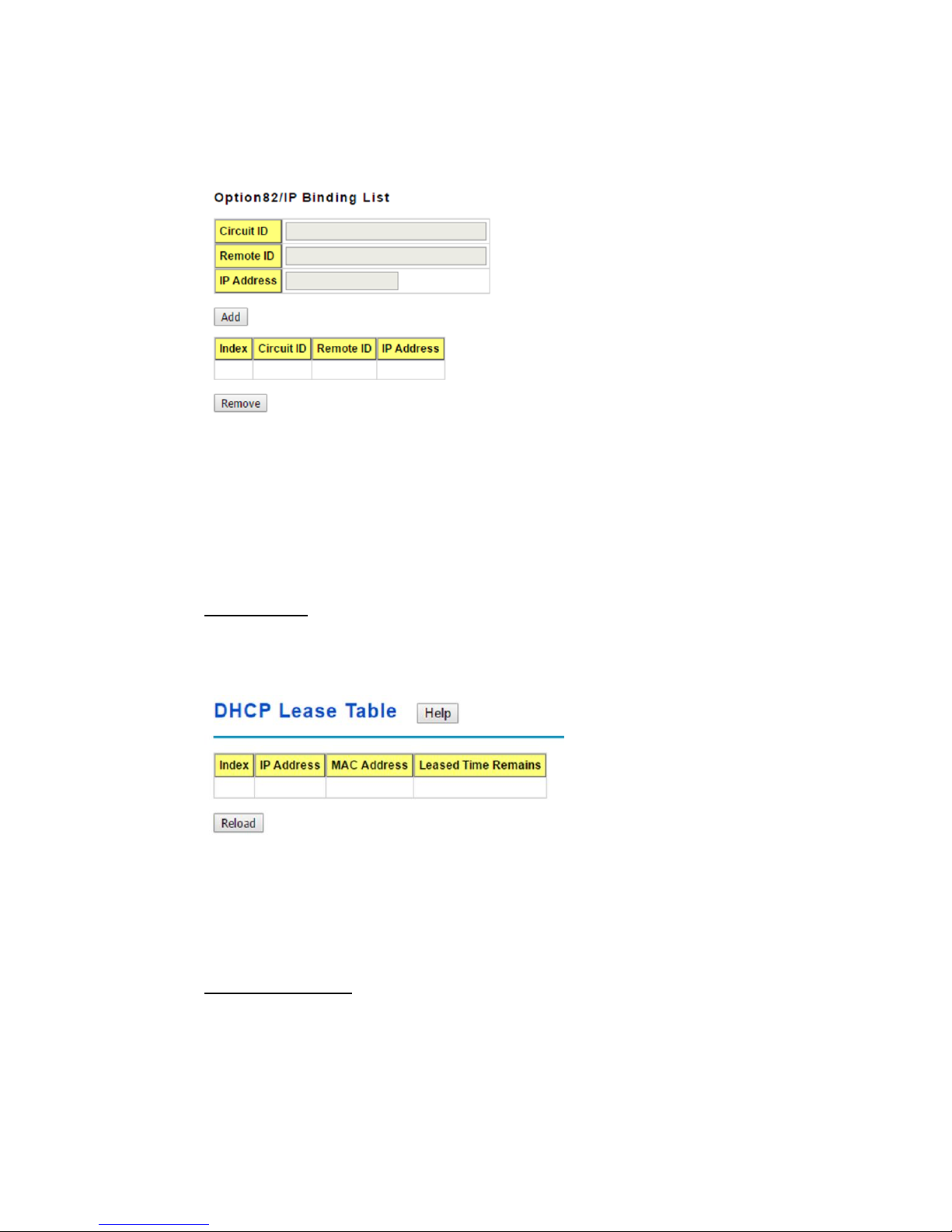
Leased Entries
JetNet Switch provides an assigned IP address list for user check. It will show the MAC
and IP address that was assigned by JetNet Switch. Click the Reload button to refresh
the listing.
Index: Index of the DHCP lease entry.
IP Address: The IP address assigned to the device that received the lease.
MAC Address: The MAC Address of the device that received the lease.
Leased Time Remains: How long in seconds until the lease expires.
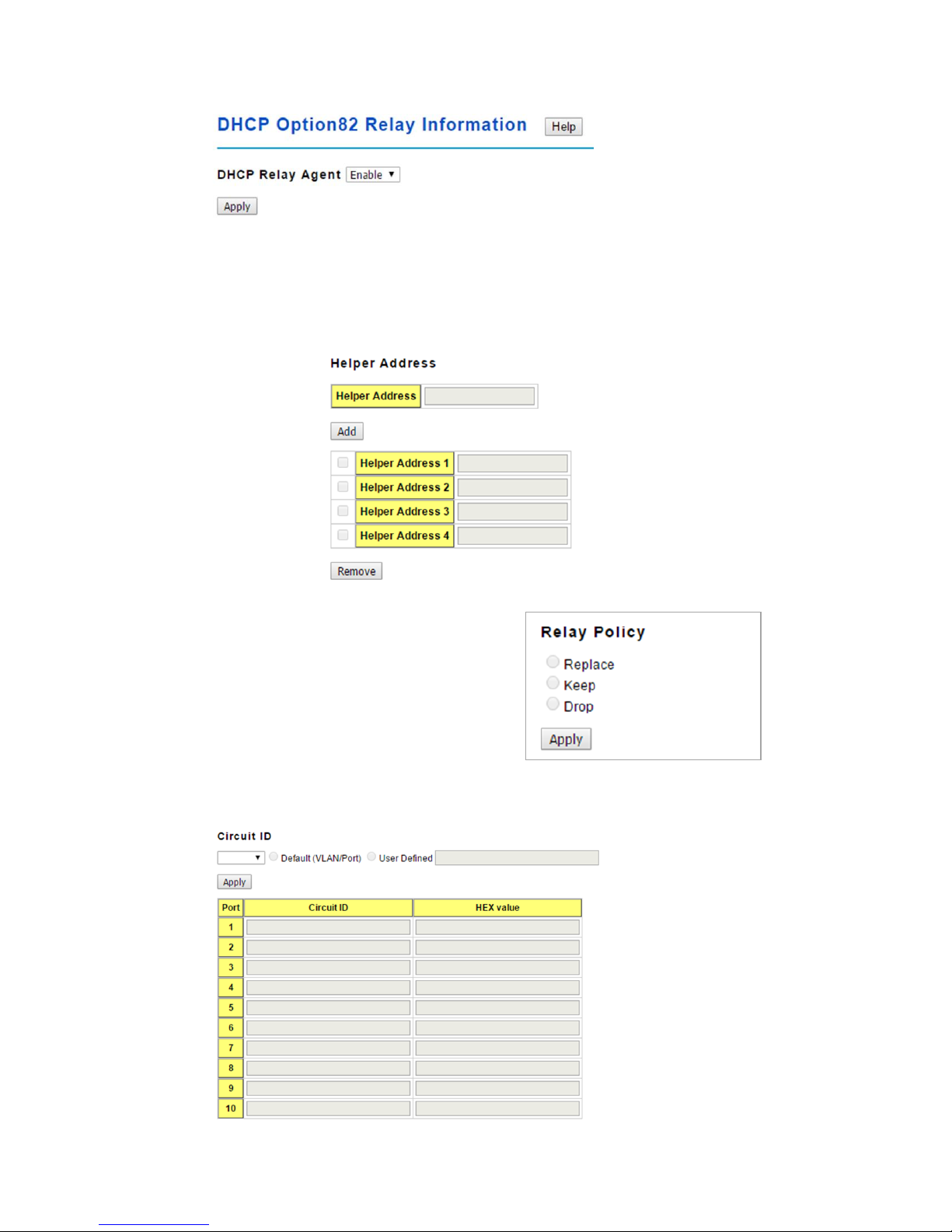
Option82 Information
This page allows you to configure DHCP Option 82 settings.
25
You canEnable or Disable the DHCP Relay Agent function. Click the Apply button to
apply the DHCP Relay Agent settings.
Helper Address: Type the IP address of the target DHCP Server. There are 4 available
IP addressesthat can be configured. Click Add to add the IP address and Remove to
delete it.
Relay Policy
Replace: Replaces the existing option 82 field
and adds new option 82 field. (This is the
default setting)
Keep: Keeps the original option 82 field and
forwards to server.
Drop: Drops the option 82 field and do not add
any option 82 field.
Circuit ID
26
Click the Apply button to apply the Circuit ID setting for a port after selecting a port and
the associated setting.
Port: This is the logical port of the switch.
Default (VLAN/Port): This is the default value of the Circuit ID.
User Defined: This is a user defined value of the Circuit ID.
The Circuit ID table contains the following information:
Port: This is the logical port of the switch.
Circuit ID: The Circuit ID includes information specific to which circuit the request came in
on. It is an identifier that is specific to the relay agent, so the type of circuit varies depending
on the relay agent.
HEX value: This is the HEX value of the Circuit ID.
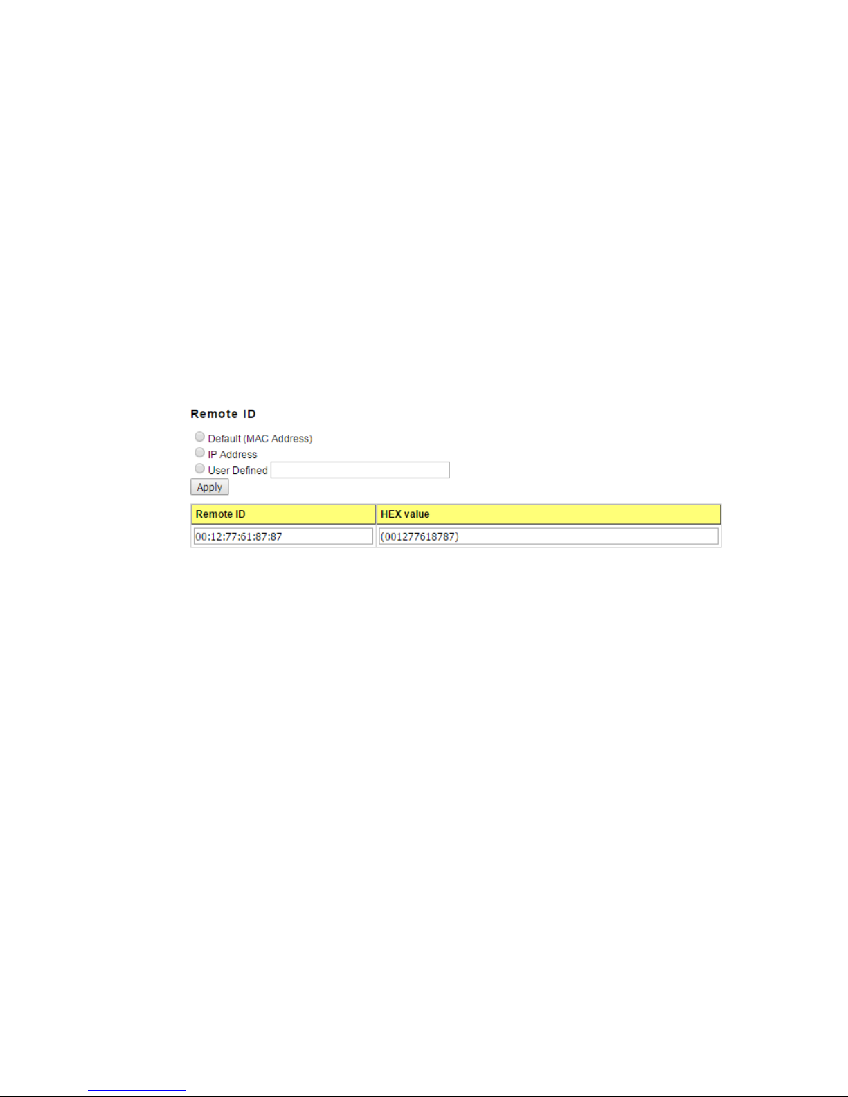
Remote ID
Default (MAC Address): Use the default value (MAC Address) as the Remote ID.
IP Address: Use the IP Address of the switch as the Remote ID.
User Defined: This is the user defined value of the Remote ID.
Click Apply to apply the Remote ID setting.
The Remote ID table provides this information.
Remote ID: The Remote-ID carries information relating to the remote host end of the
circuit, which is the MAC address of the relay.
HEX value: HEX value of the Remote ID.
2.2.7 Backup and Restore
You can use the Backup option to save the current configuration saved in the device’s flash
to a PC or laptop or your TFTP server.
This allows you to use the Restore option to restore a configuration file back to thedevice
or load the same settings to another device. Before you can restore a configuration file, you
must place the backup configuration file in the PC or TFTP server. The device then can
 Loading...