

Korenix JetNet 6910G-M12 Series User Manual

1
Korenix
JetNet 6910G-M12 Series
Industrial Managed Ethernet Switch
User Manual
Manual v1.0
Aug, 2017
www.korenix.com

2
Korenix
JetNet 6910G-M12 Series
Industrial Managed Ethernet Switch
User Manual
Copyright Notice
Copyright 2006-2017 Korenix Technology Co., Ltd.
All rights reserved.
Reproduction in any form or by any means without permission is prohibited.

3
Federal Communications Commission (FCC) Statement
This equipment has been tested and found to comply with the limits for a Class A digital device,
pursuant to Part 15 of the FCC Rules. These limits are designed to provide reasonable
protection against harmful interference when the equipment is operated in a commercial
environment. This equipment generates, uses, and can radiate radio frequency energy and, if
not installed and used in accordance with the instruction manual, may cause harmful
interference to radio communications. Operation of this equipment in a residential area is likely
to cause harmful interference in which case the user will be required to correct the interference
at his expense.
The user is cautioned that changes and modifications made to the equipment without approval
of the manufacturer could void the user’s authority to operate this equipment.

Index
1 Introduction ........................................................................................................................ 2
1.1 Overview .............................................................................................................. 2
1.2 Major Features ..................................................................................................... 3
1.3 Package List ......................................................................................................... 4
2 Hardware Installation ......................................................................................................... 5
2.1 Hardware Introduction .......................................................................................... 5
2.2 Wiring Power Inputs ............................................................................................. 7
2.3 Wiring Earth Ground ............................................................................................. 7
2.4 Wiring PoE/Fast/Gigabit Ethernet Ports ............................................................... 7
2.5 Wiring RS-232 Console Cable ............................................................................ 10
2.6 Bypass Fault Device in Daisy-Chain or Ring Topology ....................................... 10
2.7 M12 USB Auto-Configuration ............................................................................. 10
2.8 Wall Mounting Installation .................................................................................... 11
2.9 Safety Warning ................................................................................................... 12
3 Preparation for Management ........................................................................................... 13
3.1 Preparation for Serial Console ........................................................................... 13
3.2 Preparation for Web Interface ............................................................................ 14
3.3 Preparation for Telnet Console ........................................................................... 15
4 Feature Configuration ...................................................................................................... 18
4.1 Command Line Interface Introduction................................................................. 19
4.2 Basic Setting ...................................................................................................... 24
4.3 Port Configuration .............................................................................................. 42
4.4 Power Over Ethernet .......................................................................................... 50
4.5 Network Redundancy ......................................................................................... 57
4.6 VLAN .................................................................................................................. 75
4.7 Private VLAN ...................................................................................................... 84
4.8 Traffic Prioritization ............................................................................................. 90
4.9 Multicast Filtering ............................................................................................... 95
4.10 SNMP ............................................................................................................... 100
4.11 Security ............................................................................................................ 104
4.12 Warning ............................................................................................................. 113
4.13 Monitor and Diagnostic ...................................................................................... 118
4.14 Device Front Panel ........................................................................................... 133
4.15 Save (Save to Flash) ........................................................................................ 134
4.16 Logout .............................................................................................................. 135
5 Appendix ....................................................................................................................... 136
5.1 Korenix Private MIB .......................................................................................... 136
5.2 Specification ..................................................................................................... 136
5.3 Revision History ............................................................................................... 141

1
5.4 About Korenix ................................................................................................... 141
2
1 Introduction
Korenix JetNet 6910G-M12, Industrial 7 FE, + 3GbE and 8 PoE Managed High Power
PoE Switch User Manual covers following topics in this chapter:
1.1 Overview
1.2 Major Features
1.3 Package Checklist
1.1 Overview
JetNet 6910G-M12, are specially designed for industrial environments in required support of
medium number of access points or multiple Gigabit Ethernet ports. With fewer units installed
and higher density of port numbers, the ports are sharing via the wide bandwidth on-chip
backplane, in shorter local transmission latency, and sufficient upstream transmission.
JetNet 6910G-M12, the 7+3G Managed Ethernet Switch is equipped with 7 10/100TX Fast
Ethernet ports and 3 10/100/1000Base-T Gigabit Ethernet ports. 8 of 10 ports in JetNet 6910M12 offer PoE in compliant with 802.3af/at. The Switch can resist in harsh environment in
ranging operating temperature is from -40°C to 70°C.
Model Name
100TX FE
802.3af/at PoE
Gigabit Ethernet
JetNet 6910G-M12
7+3G Managed Ethernet Switch
7 (M12 D-4
female)
8 (on 7xM12 D-4,
and 1xM12 X-8
female)
3 (M12 X-8, female)
The device is recommended to be wall-mount installed by using the installation kit within the
shipment. When the other switches are aggregated to JetNet 6910G-M12, the 7+3G design
allows total connections up to 5 rings, with owned ring redundancy protection. This is unique
high-availability design featured base on Korenix patent-protected technology.
JetNet 6910G-M12 is a fan-less-designed M12 Power over Ethernet (PoE) Switch, with
100W PoE budget in compliance with IEEE 802.3af/at standard. The wide operating
temperature, and dynamic DC input voltage meet the requirement in railway on-board electrical
system..
The embedded software supports RSTP and Multiple Super Ring technology for ring
redundancy protection. Full Layer 2 management includes, VLAN, IGMP Snooping, LACP for
network control, SNMP, LLDP for network management. Secured access is achieved by Port
MAC Security and IEEE 802.1x. By utilizing JetNet 6910G-M12, one can fulfill the technician’s
need by having best solutions for Industrial Ethernet Infrastructure.

3
1.2 Major Features
JetNet 6910G-M12 has following major features:
• 7 Fast Ethernet ports in M12 D-code , 3 Gigabit Ethernet ports in M12- X-code ,
• Power in M12-A, Console/USB port in M12-A
• Rugged M12 Ethernet, Power, Management connector to protect from vibration and
shock application
• 8 IEEE 802.3at PSE allocated in 7 ports Fast Ethernet and 1 Gigabit Ethernet
• 2 Gigabit Ethernet interfaces support Device Fault Bypass function
• Railway Power System design with 100W PoE power and compliance with safety
requirement
• Network Redundancy – MSR (Multiple Super Ring), ITU-T G.8032 ERPS, RSTP,
MSTP, Super Chain
• Fully Device Management – SNMP v1/v2c/v3, RMON, Web UI, Telnet and Local
Console
• Friendly Device and Network Topology recovery Utility – Korenix View, Korenix NMS
• Advanced Network Security –MAC Security, IEEE 802.1x Port Based access control ,
IEEE 802.1x Radius Server authentication
• Layer 2 Network Performance – IEEE802.1Q VLAN, Private VLAN, Trunk, Traffic
Filtering, DHCP Server/Client, Traffic Prioritize, Forwarding Rate Control
• Real Hardware Watchdog against internal system malfunction
• Railway power system – 110V (77~137Vdc) JetNet 6910G-M12 HVDC
Railway power system – 124V (16.8~30Vdc) JetNet 6910G-M12 LVDC
• Railway Standards- EN50155, EN50121-3-2,IEC61373
• Operating Temperature: -40°C ~70°C
• Rigid Steel Metal Case complies with Ingress Protection – IP30
Note: Detailed spec can be referred to datasheet. For any possible change or
update, please download the latest version for reference from Korenix Website.

4
1.3 Package List
JetNet 6910G-M12 Series products are shipped with following accessories:
1. JetNet 6910G-M12 x1
2. Mounting kits with screws
3. Serial Console cable, M12-A-8 to DB-9 x1
4. Quick Installation Guide x1
If any of the above items are missing or damaged, please contact your local
sales representative.

5
2 Hardware Installation
This chapter includes hardware introduction, installation and configuration information.
Following topics are covered in this chapter:
2.1 Hardware Introduction
2.2 Wiring Power Inputs
2.3 Wiring Earth Ground
2.4 Wiring Fast Ethernet Ports
2.5 Wiring RS-232 console cable
2.6 Bypass Fault Device in Daisy Chain or Ring
2.7 M12 USB Auto-Configuration
2.8 Wall Mounting Installation
2.9 Safety Warning
2.1 Hardware Introduction
System Diagnostic LED
PWR (Power): Power Ready (Green On)
ALM (Alarm): Power/Data Port abnormal (Red On)
SYS (System): System Ready (Green On)
SYS (System): System on Booting/Upgrade (Green Blinking)
R.S. (Ring Status): Ring normal (Green On)
R.S. (Ring Status): Wrong ring port connected (Green Blinking)
R.S. (Ring Status): Ring abnormal (Amber On)
R.S. (Ring Status): Device ring port failed (Amber Blinking)
Fast Ethernet (PoE1~PoE7): Link/Active (Green on / Blinking), Fast Ethernet (Port1~16):
Gigabit Ethernet (G1~G3): Link/Active (Green on/ Blinking)gabit Ethernet (Port17
PoE (PoE1~PoE7, G3(PoE8))
PoE (IEEE 802.3af/ Green): Power forwarding (Green on),
PoE (IEEE 802.3af/ Green): PoE Detection (Green Blinking)
PoE (IEEE 802.3at/ Blue): Power forwarding (Blue on),
PoE (IEEE 802.3at/ Blue): PoE Detection (Blue Blinking)
6
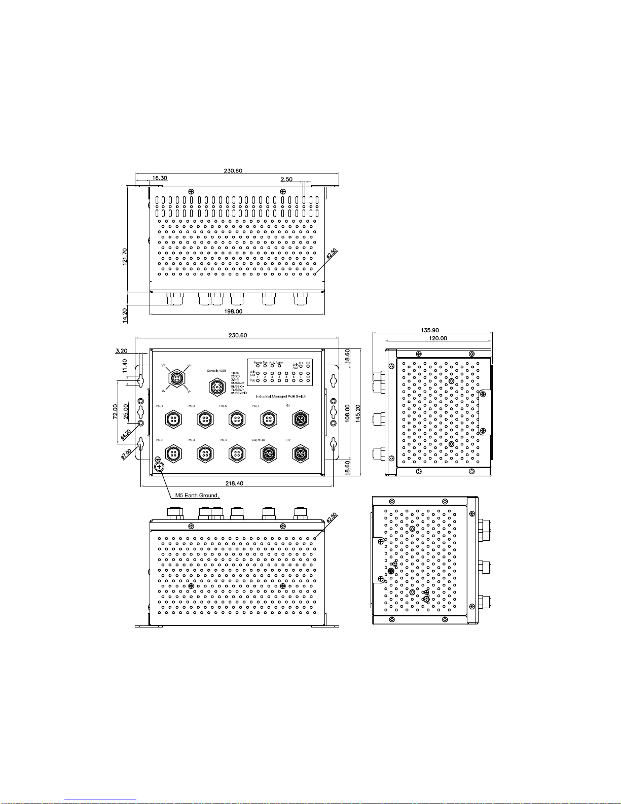
Dimension (HxWxD) mm
145.2(H) x 198 (W) x 120 (D) without Bracket
145.2(H) x 230.6 (W) x 121.7 (D) with Bracket
Panel Layout
The front panel includes M12-based USB/Console Port, Fast/Gigabit Ethernet Port,
Power and System/Port LEDs.
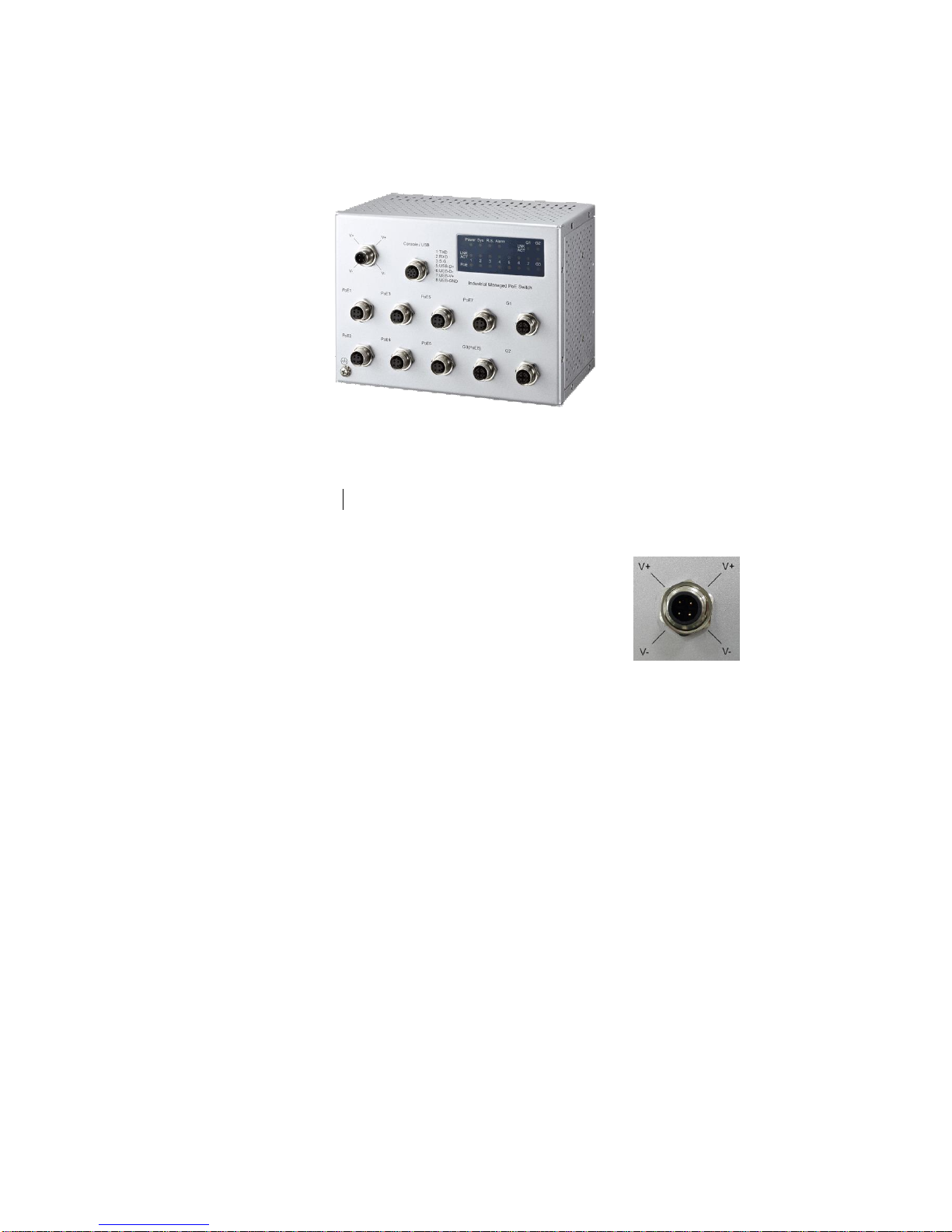
7
Figure of JetNet 6910G-M12, 7+3G Managed Ethernet Switch
2.2 Wiring Power Inputs
For DC power inputs.
1. Insert positive and negative wires into V+ and V- contacts respectively of the M12
connector (Plug-side).
2. Tighten the nuts to prevent the loosening of the M12
connectors.
3. PWR input supports power redundancy and polarity-
reverse protection functions.
Note 1: In order to protect the switch itself, a safe power-port
connection can be achieved by following procedures:
1. Turn-off the power supply.
2. Connect the power wire to the Plug-side connector.
3. Plug the connector into the switch Power port.
4. Power-on the power supply.
Note 2: If 2 power supplies are connected to the switch, it will be powered from the one
with higher voltage level.
Note 3: The connection of LVDC (24V) model should be dual input supplied to obtain
higher enough current in order to perform high power PoE loading.
2.3 Wiring Earth Ground
To ensure the system not being damaged by noise or any electrical shock, it is strongly
recommended to assure exact connection into JetNet 6910G-M12 with Earth Ground.
Ensure the lighting/surge enable screw is tightened when connect the Earth Ground.
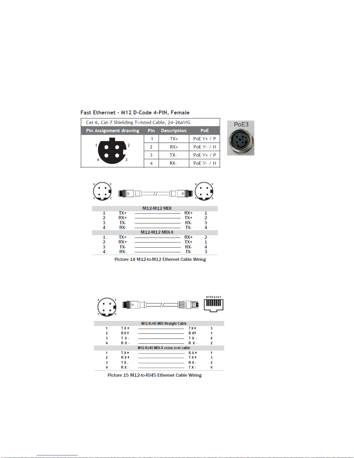
2.4 Wiring PoE/Fast/Gigabit Ethernet Ports
JetNet 6910G-M12 includes 7 Fast Ethernet ports(#1~#7, M12 D-code), 3 M12
8
Gigabit Ethernet ports(#8~#10, M12 X-code), and the PoE/ PSE function present at M12
D-Code Fast Ethernet port (#1~7) and M12 X-code Gigabit Ethernet port (#8).
The connectivity information of M12 and RJ-45 shown in below:
Fast Ethernet/ PoE ports, M12 D-code connector:
For Fast Ethernet M12 D-code to M12 D-code connection, you can use either version
below:
For Fast Ethernet M12-code to RJ45 connection, the pin assignment of the patch cable is
shown below:

9
Gigabit Ethernet ports, M12 X-code:
For Gigabit Ethernet M12 X-code to M12 X-code connections, the pin assignment of the
patch cable is shown below:
For Gigabit Ethernet M12 X-code to RJ45 connection, the pin assignment of the patch
cable is shown below:
Connect one side of an Ethernet cable into any switch port and connect the other side to
your attached device. The LNK LED will light up when the cable is correctly connected.
Refer to the LED Indicators section for descriptions of each LED indicator. Always make
sure that the cables between the switches and attached devices (e.g. switch, hub, or
workstation) are less than 100 meters (328 feet).
10
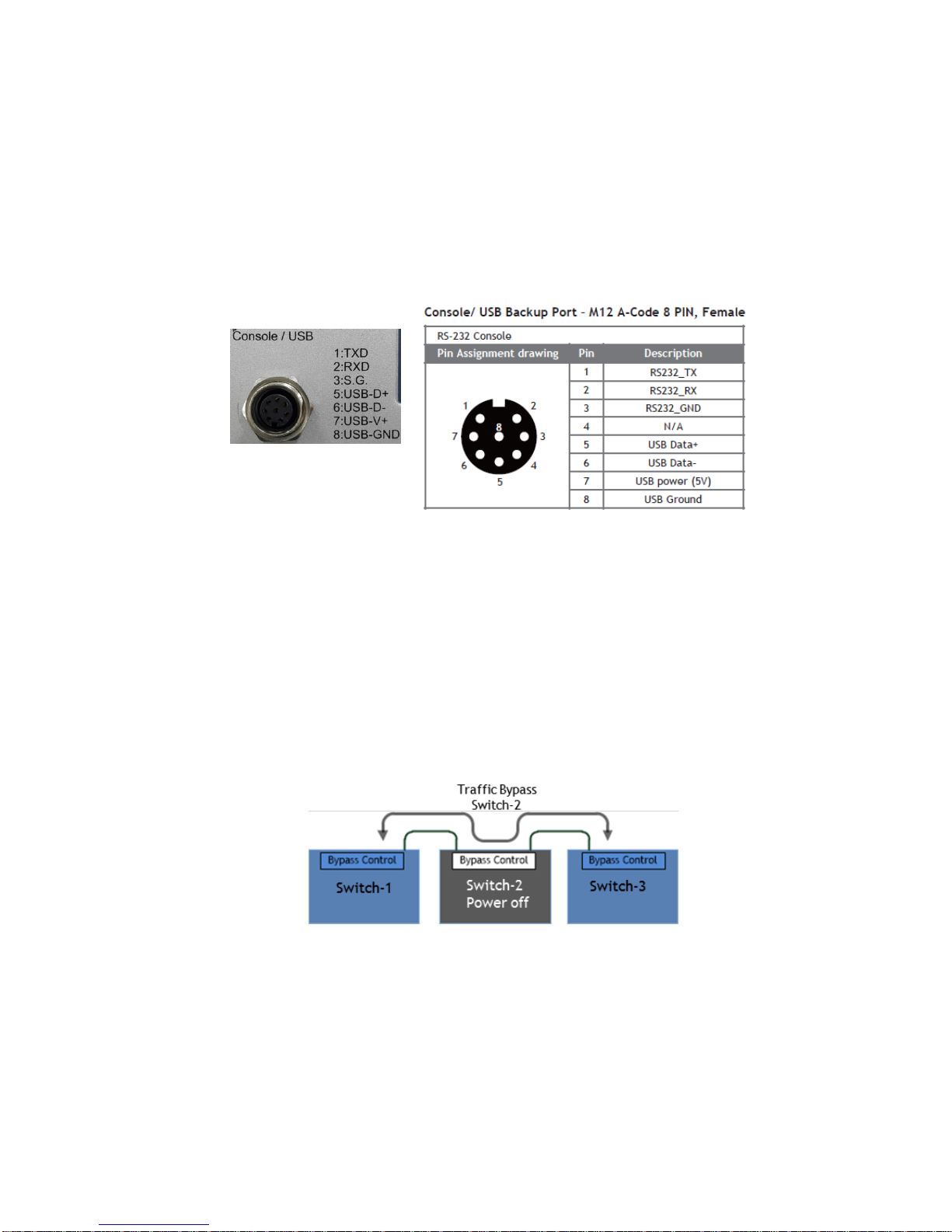
2.5 Wiring RS-232 Console Cable
JetNet 6910G-M12 attached one RS-232 DB-9 to M12-A cable in the unit box.
Connect the DB-9 connector to the COM port of your PC, connect M12-A to Switch’s
USB/Console port, open Terminal tool and set up serial settings to 9600, N,8,1. (Baud
Rate: 9600 / Parity: None / Data Bit: 8 / Stop Bit: 1) Then you can access CLI interface by
console able.
Note: If the cable is lost, please contact with your sales or follow the pin assignment
to buy a new one.
2.6 Bypass Fault Device in Daisy-Chain or Ring Topology
Auto-bypass function has been applied on G1 and G2 for rolling stock applications. In
the metro or ring network, the topology may be segmented into several fractions by one
failure power node. As a result, some of the segments or nodes cannot communicate with
each other. The port Bypass function can connect remote network fragments by linking
uplink and downlink ports together when the Switch is powered down. With this feature,
the Switch can ensure that train communication always works appropriately.
2.7 M12 USB Auto-Configuration
The JetNet 6910G has enabled USB memory access function for the configuration restore/backup. The
function brings benefits to the field engineers maintaining/upgrading the system without special tools or
configuration knowledges. The system kernel will automatically restore the desired configuration if the
configuration files existing in the M12/USB memory stick with specified file name. It also makes the
on-field Ethernet Switch replacement/ exchange process easy and friendly.
1. The Max length of the configuration file name: 40 characters
2. The configuration file Naming rules and respective detection behavior as below
(a)Name: AutoLoadSaveConfiguration.conf Auto load the Configuration existed in the
11
USB and save the configuration to the Ethernet Switch memory and apply the new
configuration into system when boot up.
(b)Name: AutoLoadConfiguration.conf Auto Load Configuration and apply the
configuration to Ethernet Switch without saving to memory.
(c)If both files exist in the USB, then the AutoLoadSaveConfiguration.conf has the higher
priority and will perform Auto load and saving actions.
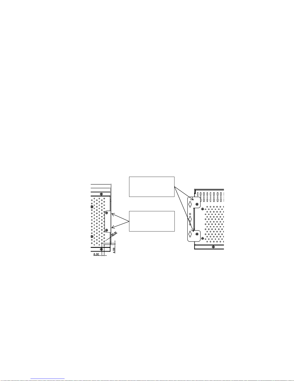
2.8 Wall Mounting Installation
Follow the steps below to install JetNet 6910G-M12 with the wall-mounting plate.
1. Install the wall-mounting plate onto the side panel of the switch.
2. Makes sure that all the screws are tightened well.
3. Use the hook holes at the corners of the wall mounting plate to fix the switch on the
wall.
Mounting screw on
back/Rear side
Mounting screw on
Right/Left Side
Wall Mounting Plate & Screws

12
2.9 Safety Warning
The Equipment intended for installation in a Restricted Access Location.
This Ethernet Switch is intended for Railway/Train on-board application. Thus, all of the
installation should be performed by professional Engineer who is familiar Train
communication and electrical power system.

13
3 Preparation for Management
JetNet 6910G-M12 Din Rail Industrial Managed Switch provides both in-band and outband configuration methods. It is possible to configure the device via RS232 console
cable if there’s not an admin PC attached in the network to manage JetNet 6910G-M12.
This console connectivity via RS232 port is a way called out-band management. It
wouldn’t be affected by network performance.
The in-band management in this manual refer the way of remotely managing 6910G-M12
via a remote PC attaching in the network. Telnet or Web-based GUI are provided for
management. The device’s IP address is required before remotely connecting to its
embedded HTTP web pages or Telnet console.
Following topics are covered in this chapter:
3.1 Preparation for Serial Console
3.2 Preparation for Web Interface
3.3 Preparation for Telnet console
3.1 Preparation for Serial Console
In JetNet 6910G-M12 package, Korenix attached one RS-232 M12 to DB-9 console cable.
Please attach RS-232 DB-9 connector to your PC COM port, connect the other end to the
Console port of the JetNet 6910G-M12. Note: If you lost the cable, please contact with
your sales or follow the pin assignment to buy a new one.
1. Go to Start -> Program -> Accessories -> Communication -> Hyper Terminal
2. Give a name to the new console connection.
3. Choose the COM name
4. Select correct serial settings. The serial settings of 6910G-M12 is as below:
Baud Rate: 9600 / Parity: None / Data Bit: 8 / Stop Bit: 1
5. After connected, Switch login request is expected seen on the screen.
6. Login the switch. The default username is “admin”, password, “admin”.
Boot loader Rev. 2.0.0.1 (Tue Oct 13 16:19:29 CST 2015)
Starting....
Switch login: admin
Password:
JetNet6910G-M12
(version 0.0.21-20160118-11:00:03).
Copyright 2006-2017 Korenix Technology Co., Ltd.
Switch>

14
3.2 Preparation for Web Interface
JetNet 6910G-M12 provides HTTP Web Interface and Secured HTTPS Web Interface for
web management.
Web Interface
Korenix web management GUI page is developed by JAVA or *CGI. It allows to use a
standard web-browser such as Microsoft Internet Explorer, or Mozilla, Chrome to
configure and interrogate the switch from anywhere on the network in the same domain.
*Note: Contact sales representative or check Korenix website for CGI GUI availability.
Before you attempt to use the embedded web interface to manage switch operation,
verify that your JetNet 6910G-M12 is properly installed on your network and that every
PC on this network can access the switch via the web browser.
1. Verify that your network interface card (NIC) is operational, and that your operating
system supports TCP/IP protocol.
2. Wire DC power to the switch and connect your switch to your computer.
3. Make sure that the switch default IP address is 192.168.10.1.
4. Change your computer IP address to 192.168.10.2 or other IP address which is
located in the 192.168.10.x (Network Mask: 255.255.255.0) subnet.
5. Switch to DOS command mode and ping 192.168.10.1 to verify a normal response
time.
Launch the web browser and Login.
6. Launch the web browser (Internet Explorer, Google Chrome or Mozilla Firefox) on
the PC.
7. Type http://192.168.10.1 (or the IP address of the switch). And then press Enter.
8. The login screen will appear next.
9. Key in user name and the password. Default user name and password are both
admin.
Click on Login. Welcome page of the web-based management interface will then
appear.

15
Once you enter the web-based management interface, you can freely change the
Switch’s IP address to fit your network environment.
Note : The Web UI connection session of Managed Switch will be logged out
automatically if you don’t give any input after 10 minutes. After logged out, you should relogin and key in correct user name and password again.
3.3 Preparation for Telnet Console
3.3.1 Telnet
Korenix JetNet 6910G-M12 supports Telnet console. You can connect to the switch by
Telnet and the command lines are the same as what you see by RS232 console port.
Below are the steps to open Telnet connection to the switch.
1. Go to Start -> Run -> cmd. And then press Enter
2. Type the Telnet 192.168.10.1 (or the IP address of the switch). And then press
Enter
3.3.2 SSH (Secure Shell)
Korenix JetNet 6910G-M12 also support SSH console. You can remotely connect to the
switch by command line interface. The SSH connection can secure all the configuration
commands you sent to the switch.
SSH is a client/server architecture while the Managed Switch is the SSH server. When
you want to make SSH connection with the switch, you should download the SSH client
tool first.
SSH Client
There are many free, sharewares, trials or charged SSH clients you can find on the
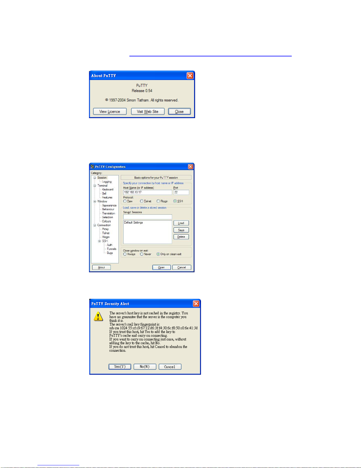
internet. Fox example, PuTTY is a free and popular Telnet/SSH client. We’ll use this
tool to demonstrate how to login Managed Switch by SSH. Note: PuTTY is copyright
1997-2006 Simon Tatham.
16
Download PuTTY: http://www.chiark.greenend.org.uk/~sgtatham/putty/download.html
The copyright of PuTTY
1. Open SSH Client/PuTTY
In the Session configuration, enter the Host Name (IP Address of your JetNet 6910GM12) and Port number (default = 22). Choose the “SSH” protocol. Then click on “Open”
to start the SSH session console.
2. After click on Open, then you can see the cipher information in the popup screen.
Press Yes to accept the Security Alert.

17
3. After few seconds, the SSH connection to JetNet 6910G-M12 is opened. You can
see the login screen as the below figure. (the following is refer to JetNet 5010G)
4. Type the Login Name and its Password. The default Login Name and Password are
admin / admin.
5. All the commands you see in SSH are the same as the CLI commands you see via
RS232 console. The next chapter will introduce in detail how to use command line to
configure the switch.

18
4 Feature Configuration
This chapter explains how to configure the Managed Switch’s software features. There are
four ways to access the switch: Serial console, Telnet, Web browser and SNMP.
The Managed Switch Series provides both in-band and out-band configuration methods.
The connectivity of both in-band and out-band is described in previous chapter.
Assign the device an IP address, then this switch can be remotely connected and managed
via its embedded HTML web pages or Telnet console.
The Web management page can be shown at a standard web-browser such as Microsoft
Internet Explorer, or Mozilla, Chrome to configure and interrogate the switch from
anywhere on the network.
Following topics are covered in this chapter:
4.1 Command Line Interface (CLI) Introduction
4.2 Basic Setting
4.3 Port Configuration
4.4 Power Over Ethernet
4.5 Network Redundancy
4.6 VLAN
4.7 Private VLAN
4.8 Traffic Prioritization
4.9 Multicast Filtering
4.10 SNMP
4.11 Security
4.12 Warning
4.13 Monitor and Diagnostic
4.14 Device Front Panel
4.15 Save
4.16 Logout

19
4.1 Command Line Interface Introduction
The Command Line Interface (CLI) is the user interface to the switch’s embedded software
system. An network administrator can view the system information, show the status,
configure the switch and receive a response back from the system by input a CLI
command.
There are some different command modes. Each command mode has its own access
ability, available command lines and uses different command lines to enter and exit. These
modes are User EXEC, Privileged EXEC, Global Configuration, (Port/VLAN) Interface
Configuration modes.
User EXEC mode: As long as administrator login the switch by CLI. it is in the User EXEC
mode. Administrator can ping, telnet remote device, and show some basic information.
Type enable to enter next mode, exit to logout. ? to see the command list
Privileged EXEC mode: Press “enable” command in the User EXEC mode, then
administrator can transit into the Privileged EXEC mode. In this mode, the system allows to
view current configuration, reset default, reload switch, show system information, save
configuration…and enter the global configuration mode.
Type in” configure terminal” to enter next mode, and “exit” to leave. “? “ to listing the
command list
Switch>
enable Turn on privileged mode command
exit Exit current mode and down to previous mode
list Print command list
ping Send echo messages
quit Exit current mode and down to previous mode
show Show running system information
telnet Open a telnet connection
traceroute Trace route to destination
Switch#
archive manage archive files
clear Reset functions
clock Configure time-of-day clock
configure Configuration from vty interface
copy Copy from one file to another
debug Debugging functions (see also 'undebug')
disable Turn off privileged mode command
dot1x IEEE 802.1x standard access security control
end End current mode and change to enable mode
exit Exit current mode and down to previous mode
list Print command list
mac MAC interface commands
no Negate a command or set its defaults
pager Terminal pager
ping Send echo messages
quit Exit current mode and down to previous mode
reboot Reboot system
reload copy a default-config file to replace the current one
show Show running system information
telnet Open a telnet connection
terminal Set terminal line parameters
traceroute Trace route to destination
write Write running configuration to memory, network, or terminal

20
Global Configuration Mode: Press configure terminal in privileged EXEC mode.
Adminstrator can then enter global configuration mode. In global configuration mode,
administrator can configure all the features that the system provides.
Type interface IFNAME/VLAN to enter interface configuration mode, exit to leave. ? to
see the command list.
Available command lists of global configuration mode.
(Port) Interface Configuration: Press interface IFNAME in global configuration mode.
Administrator can then enter interface configuration mode. In this mode, administrator can
configure port settings.
The port interface name of the fast Ethernet port is fa<Port Number>. Ex: Fast Ethernet
Port 1 fa1, fast Ethernet port 7 is fa7.
The port interface name of the Gigabit Ethernet port is gi<Port Number>. Ex: Gigabit
Ethernet Port 8 is gi8, Gigabit Ethernet Port 17 is gi17. Even you apply fixed 100M speed
to the Gigabit Ethernet port, the port interface name is still gi<Port Number>.
Types interface name accordingly for going to certain interface configuration mode.
Type exit to leave.
Type ? to see the command list
Switch# configure terminal
Switch(config)#
access-list Add an access list entry
administrator Administrator account setting
clock Configure time-of-day clock
default Set a command to its defaults
dot1x 802.1x port-based authentication for the switch
end End current mode and change to enable mode
erps Ethernet Ring Protection Switching (ITU-T G.8032)
ethernet-ip Ethernet/IP Protocol
exit Exit current mode and down to previous mode
gmrp GMRP protocol
gvrp GARP VLAN Registration Protocol
hostname Set system's network name
interface Select an interface to configure
ip Global IP configuration subcommands
ipv6 IP information
lacp Link Aggregation Control Protocol
list Print command list
lldp Link Layer Discovery Protocol
log Logging control
mac Global MAC configuration subcommands
mac-address-table mac address table
mirror Port mirroring
modbus Modbus TCP Slave
multiple-super-ring Configure Multiple Super Ring
no Negate a command or set its defaults
ntp Configure NTP
ptp IEEE1588 Precision Time Protocol
qos Quality of Service (QoS)
relay relay output type information
service System service

21
Available command lists of the (port) Interface configuration mode.
(VLAN) Interface Configuration: Press interface VLAN VLAN-ID in global configuration
mode. You can then enter VLAN interface configuration mode. In this mode, you can
configure the settings for the specific VLAN.
The VLAN interface name of VLAN 1 is VLAN 1, VLAN 2 is VLAN 2…
Type exit to leave the mode. Type ? to see the available command list.
The command lists of the VLAN interface configuration mode.
Switch(config)# interface vlan 1
Switch(config-if)#
description Interface specific description
end End current mode and change to enable mode
exit Exit current mode and down to previous mode
ip Interface Internet Protocol config commands
ipv6 Interface Internet Protocol config commands
list Print command list
no Negate a command or set its defaults
quit Exit current mode and down to previous mode
shutdown Shutdown the selected interface
Switch(config)# interface fa1
Switch(config-if)#
acceptable Configure 802.1Q acceptable frame types of a port.
auto-negotiation Enable auto-negotiation state of a given port
description Interface specific description
dot1x IEEE 802.1x access security control
duplex Specify duplex mode of operation for a port
end End current mode and change to enable mode
ethertype Ethertype
exit Exit current mode and down to previous mode
flowcontrol Set flow-control value for an interface
garp General Attribute Registration Protocol
ip Interface Internet Protocol config commands
lacp Link Aggregation Control Protocol
list Print command list
loopback Specify loopback mode of operation for a port
mac MAC interface commands
mdix Enable mdix state of a given port
no Negate a command or set its defaults
qos Quality of Service (QoS)
quit Exit current mode and down to previous mode
rate-limit Rate limit configuration
sfp Small form-factor pluggable
shutdown Shutdown the selected interface
spanning-tree spanning-tree protocol
speed Specify the speed of a Fast Ethernet or a Gigabit Ethernet
port.
storm-control Enables packets flooding rate limiting features

22
Summary of the 5 command modes.
Command
Mode
Main Function
Enter and Exit Method
Prompt
User EXEC
This is the first level of access.
User can ping, telnet remote
device, and show some basic
information
Enter: Login successfully
Exit: exit to logout.
Next mode: Type enable to
enter privileged EXEC mode.
Switch>
Privileged
EXEC
In this mode, the system allows
you to view current configuration,
reset default, reload switch,
show system information, save
configuration…and enter global
configuration mode.
Enter: Type enable in User
EXEC mode.
Exec: Type disable to exit to
user EXEC mode.
Type exit to logout
Next Mode: Type configure
terminal to enter global
configuration command.
Switch#
Global
configuration
In global configuration mode,
you can configure all the
features that the system
provides you
Enter: Type configure
terminal in privileged EXEC
mode
Exit: Type exit or end or press
Ctrl-Z to exit.
Next mode: Type interface
IFNAME/ VLAN VID to enter
interface configuration mode
Switch(config)#
Port
Interface
configuration
In this mode, you can configure
port related settings.
Enter: Type interface
IFNAME in global
configuration mode.
Exit: Type exit or Ctrl+Z to
global configuration mode.
Type end to privileged EXEC
mode.
Switch(config-if)#
VLAN Interface
Configuration
In this mode, you can configure
settings for specific VLAN.
Enter: Type interface VLAN
VID in global configuration
mode.
Exit: Type exit or Ctrl+Z to
global configuration mode.
Type end to privileged EXEC
mode.
Switch(config-vlan)#

23
Here are some useful commands for you to see these available commands. Save your time
in typing and avoid typing error.
? To see all the available commands in this mode. It helps to see the possible, available
commands for use.
(Character)? To see all the available commands starts from this character.
Tab This tab key helps to input the command quicker. If there is only one available
command in the next, clicking on tab key can help to finish typing soon.
Ctrl+C To stop executing the unfinished command.
Ctrl+S To lock the screen of the terminal. You can’t input any command.
Ctrl+Q To unlock the screen which is locked by Ctrl+S.
Ctrl+Z To exit configuration mode.
Alert message when multiple users want to configure the switch. If the administrator is in
configuration mode, then the Web users can’t change the settings. The Managed Switch
allows only one administrator to configure the switch at a time.
Switch(config)# a?
access-list Add an access list entry
administrator Administrator account setting
Switch# co (tab) (tab)
Switch# configure terminal
Switch(config)# ac (tab)
Switch(config)# access-list
Switch(config)# interface (?)
IFNAME Interface's name
vlan Select a vlan to configure

24
4.2 Basic Setting
The Basic Setting group provides the way to configure switch information, IP address, User
name/ Password of the system. It also allows you to do firmware upgrade, backup and
restore configuration, reload factory default, and reboot the system.
Following commands are included in this group:
4.2.1 Switch Setting
4.2.2 Admin Password
4.2.3 IP Configuration
4.2.4 Time Setting
4.2.5 Jumbo Frame
4.2.6 DHCP Server
4.2.7 Backup and Restore
4.2.8 Firmware Upgrade
4.2.9 Load Default
4.2.10 System Reboot
4.2.11 CLI Commands for Basic Setting
4.2.1 Switch Setting
It can be assigned System name, Location, Contact and view system information.
Figure 4.2.1.1 – Web UI of the Switch Setting
System Name: Administrator can assign a name to the device. The available character
string length is 64. After configuring the name, CLI system will select the first 12 characters
as the name in CLI system.
System Location: Administrator can specify the switch’s physical location here. The
available character string length is 64.
System Contact: Administrator can specify contact people here. Administrator can type
the name, mail address or other information of the administrator. The available character
string length is 64.

25
System OID: The SNMP object ID of the switch. Administrator can follow the path to find
its private MIB in MIB browser. (Note: When administrator attempt to view private MIB,
yit’s required to compile private MIB files into the MIB browser first.)
System Description: JetNet6910G-M12 Industrial Managed Ethernet Switch is the name
of this product.
Firmware Version: Display the firmware version installed in this device.
MAC Address: Display unique hardware address (MAC address) assigned by the
manufacturer.
Once the configuration is finished, click on Apply to apply for taking settings effective.
Note: Always remember to select Save to save all the settings. Otherwise, the settings
made can be lost when the switch is powered off.
4.2.2 Admin Password
An administrator can change the user name and the password here to enhance security.
Figure 4.2.2.1 Web UI of the Admin Password
User name: Administrator can key in new user name here. The default setting is admin.
Password: Administrator can key in new password here. The default setting is admin.
Confirm Password: Administrator need to type the new password again to confirm it.
Once configuring the settings is finished, click on Apply to apply configuration in effective.
Administrator can use RADIUS server's user name and password for your management
security.

26
RADIUS Server IP: The IP address of the RADIUS server.
Shared Key: The password for communication between the switch and the RADIUS
Server.
Server Port: UDP port of the RADIUS server.
Apply: button to apply the RADIUS Server and Secondary RADIUS Server
configurations.
4.2.3 IP Configuration
This function allows users to configure the switch’s IP address settings.
DHCP Client: Administrator can select to Enable or Disable DHCP Client function. When
DHCP Client function is enabled, an IP address will be assigned to the switch from the
network’s DHCP server. In this mode, the default IP address will therefore be replaced by
the one assigned by DHCP server. If DHCP Client is disabled, then the IP address that you
specified will be used instead.
IP Address: Administrator can assign the IP address reserved by the network applied for
the JetNet 6910G-M12 being deployed. If DHCP Client function is enabled, it is not
necessary to assign an IP address to the JetNet 6910G-M12, as it will be overwritten by
DHCP server and shown here. The default IP address is 192.168.10.1.
Subnet Mask: Administrator can/shall assign a correct subnet mask for the IP address
here. If DHCP Client function is enabled, it is not necessary to assign the subnet mask. The
default Subnet Mask is 255.255.255.0. Note: In the CLI, the enabled bit of the subnet
mask is used to represent the number displayed in web UI. For example, 8 stands for
255.0.0.0; 16 stands for 255.255.0.0; 24 stands for 255.255.255.0.
Default Gateway: Administrator can assign the gateway for the switch here. The default
gateway is 192.168.10.254.
Note: In CLI, we use 0.0.0.0/0 to represent for the default gateway.
Once Administrator finish configuring the settings, click on Apply to apply configuration into
effective.
IPv6 Configuration –An IPv6 address is represented as eight groups of four hexadecimal
digits, each group representing 16 bits (two octets). The groups are separated by colons
(:), and the length of IPv6 address is 128bits.
The default IPv6 address of JetNet 6910G-M12 is generated from hardware MAC by IEEEdefined 64-bit Extended Unique Identifier (EUI-64), so that each JetNet 5020 owns her
 Loading...