

Korenix JetNet 5628G, JetNet 5828G, JetNet 5628G-2AC, JetNet 5828G-2AC, JetNet 5628G-2HDC User Manual
...
1
Korenix JetNet 5628G/5828G Series
IEC61850-3 Modular Managed Ethernet Switch
User Manual
Version 1.6
Oct. 2013
www.korenix.com

2
Korenix JetNet 5628G/5828G
Industrial Modular Managed Ethernet Switch
User’s Manual
Copyright Notice
Copyright 2006-2011 Korenix Technology Co., Ltd.
All rights reserved.
Reproduction in any form or by any means without permission is prohibited.

3
Federal Communications Commission (FCC) Statement
This equipment has been tested and found to comply with the limits for a Class A digital device,
pursuant to Part 15 of the FCC Rules. These limits are designed to provide reasonable
protection against harmful interference when the equipment is operated in a commercial
environment. This equipment generates, uses, and can radiate radio frequency energy and, if
not installed and used in accordance with the instruction manual, may cause harmful
interference to radio communications. Operation of this equipment in a residential area is likely
to cause harmful interference in which case the user will be required to correct the interference
at his expense.
The user is cautioned that changes and modifications made to the equipment without approval
of the manufacturer could void the user’s authority to operate this equipment.

Index
1 Introduction ....................................................................................................................... 2
1.1 Overview .............................................................................................................. 2
1.2 Major Features ..................................................................................................... 4
1.3 Package List ........................................................................................................ 4
1.4 Optional Module ................................................................................................... 5
2 Hardware Installation ........................................................................................................ 6
2.1 Hardware Introduction.......................................................................................... 6
2.2 Wiring Power Inputs ............................................................................................. 9
2.3 Wiring Digital Input ............................................................................................... 9
2.4 Wiring Digital Output .......................................................................................... 10
2.5 Wiring Earth Ground .......................................................................................... 10
2.6 Choosing Fast Ethernet Module ........................................................................ 10
2.7 Mounting Fast Ethernet Module .......................................................................... 11
2.8 Wiring Fast Ethernet Ports ................................................................................. 12
2.9 Wiring Fiber Ports .............................................................................................. 12
2.10 Wiring Gigabit Combo Ports .............................................................................. 14
2.11 Wiring RS-232 Console Cable ........................................................................... 14
2.12 Rack Mounting Installation ................................................................................. 14
2.13 Safety Warming.................................................................................................. 16
3 Preparation for Management .......................................................................................... 17
3.1 Preparation for Serial Console ........................................................................... 17
3.2 Preparation for Web Interface ............................................................................ 18
3.3 Preparation for Telnet Console .......................................................................... 20
4 Feature Configuration ..................................................................................................... 23
4.1 Command Line Interface Introduction ................................................................ 24
4.2 Basic Setting (Y2011, 0604) .............................................................................. 29
4.3 Port Configuration .............................................................................................. 55
4.4 Network Redundancy......................................................................................... 66
4.5 VLAN .................................................................................................................. 85
4.6 Private VLAN ..................................................................................................... 95
4.7 Traffic Prioritization .......................................................................................... 102
4.8 Multicast Filtering ............................................................................................. 107
4.9 Routing .............................................................................................................. 113
4.10 SNMP ............................................................................................................... 141
4.11 Security ............................................................................................................ 145
4.12 Warning ............................................................................................................ 157

1
4.13 Monitor and Diag .............................................................................................. 166
4.12 Device Front Panel ............................................................................................. 182
4.13 Save to Flash ................................................................................................... 184
4.14 Logout .............................................................................................................. 185
5 Appendix ....................................................................................................................... 186
5.1 Pin Assignment of the RS-232 Console Cable ................................................ 186
5.2 Korenix SFP family .......................................................................................... 187
5.3 Korenix Private MIB ......................................................................................... 188
5.4 Revision History ............................................................................................... 189
5.5 About Korenix .................................................................................................. 190

2
1 Introduction
Welcome to Korenix JetNet 5628G/5828G Industrial Modular Managed Ethernet Switch
User Manual. Following topics are covered in this chapter:
1.1 Overview
1.2 Major Features
1.3 Package Checklist
1.1 Overview
JetNet 5628G/5828G is an IEC61850-3 Modular Managed Ethernet Switch, equipped with 4
on-board Gigabit RJ45 / MINI GBIC combo ports plus 3 modular slots for maximum 24 10/100
Base-TX Ports or 18 100Base-FX Fiber interfaces ports. The JNM5 series modules are flexible
for different port volume, media types and application needs.
JetNet 5628G/5828G, a special design for substation automation and industrial control
room, is compliant with the IEC61850-3, IEEE1613 high level environmental certifications.
JetNet 5628G/5828G has the capability of forwarding Data, GOOSE, SCADA message
without any loss or collision. JetNet 5628G/5828G also pass the NEMA TS-2 and EN50121-4
certification which are requested in Transportation and Railway market.
The advantage of choosing JetNet 5628G/5828G is that the switch supports on board 4
gigabit ports which allow users to trunk up to 8G uplink bandwidth or to form 2 independent
Gigabit rings. The 24 100M interface allows to form 12 100M rings for a reliable network
redundancy. This is the Korenix MultiRing redundancy design. The recovery time when ring
failure can still remains 10ms high performance.
The JetNet 5628G/5828G series also supports the advanced management, control and
security requirements in power substations and control rooms, such as the VLAN, QoS, IGMP,
layer 2/4 Access Control List, 802.1x, SNMP V3, LLDP, etc. The JetNet 5828G support Layer
3 routing features, such as static route, dynamic unicast routing protocols, RIP and OSPF,
dynamic multicast routing protocol, DVMRP and VRRP for router redundancy. With all the
layer 2 and layer 3 features complete the demand and greatly satisfy technicians’ requests.
The JetNet 5628G/5828G Series include below models with the different power input types.
The model name and power input type is listed as below.
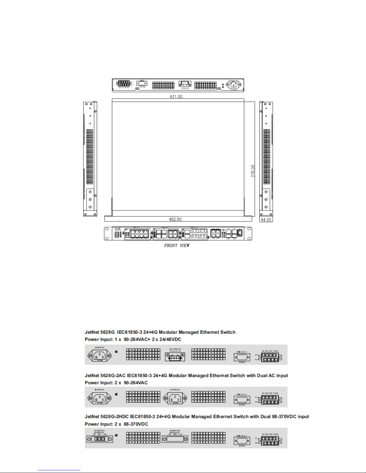
JetNet 5628G IEC61850-3 24+4G Modular Managed Ethernet Switch
Power Input: 1 x 85-264VAC/88-370VDC, Standard AC Plug + 2 x 24/48VDC
JetNet 5628G-2AC IEC61850-3 24+4G Modular Managed Ethernet Switch with Dual AC

3
input, Power Input: 2 x 85-264VAC/88-370VDC, Standard AC Plug
JetNet 5628G-2HDC IEC61850-3 24+4G Modular Managed Ethernet Switch with Dual
88-370VDC input, Power Input: 2 x 85-264VAC/88-370VDC, 3 Pin Terminal Block
JetNet 5828G IEC61850-3 24+4G Layer 3 Modular Managed Ethernet Switch
Power Input: 1 x 85-264VAC/88-370VDC, Standard AC Plug + 2 x 24/48VDC
JetNet 5828G-2AC IEC61850-3 24+4G Layer 3 Modular Managed Ethernet Switch with
Dual AC input, Power Input: 2 x 85-264VAC/88-370VDC, Standard AC Plug
JetNet 5628G-R IEC61850-3 24+4G Modular Managed Ethernet Switch, Ethernet Ports
on the Rear panel
Power Input: 2 x 85-264VAC/88-370VDC, 6-pin Terminal Block
JetNet 5828G-R IEC61850-3 24+4G Layer 3 Modular Managed Ethernet Switch,
Ethernet Ports on the Rear panel
Power Input: 2 x 85-264VAC/88-370VDC, 6-pin Terminal Block
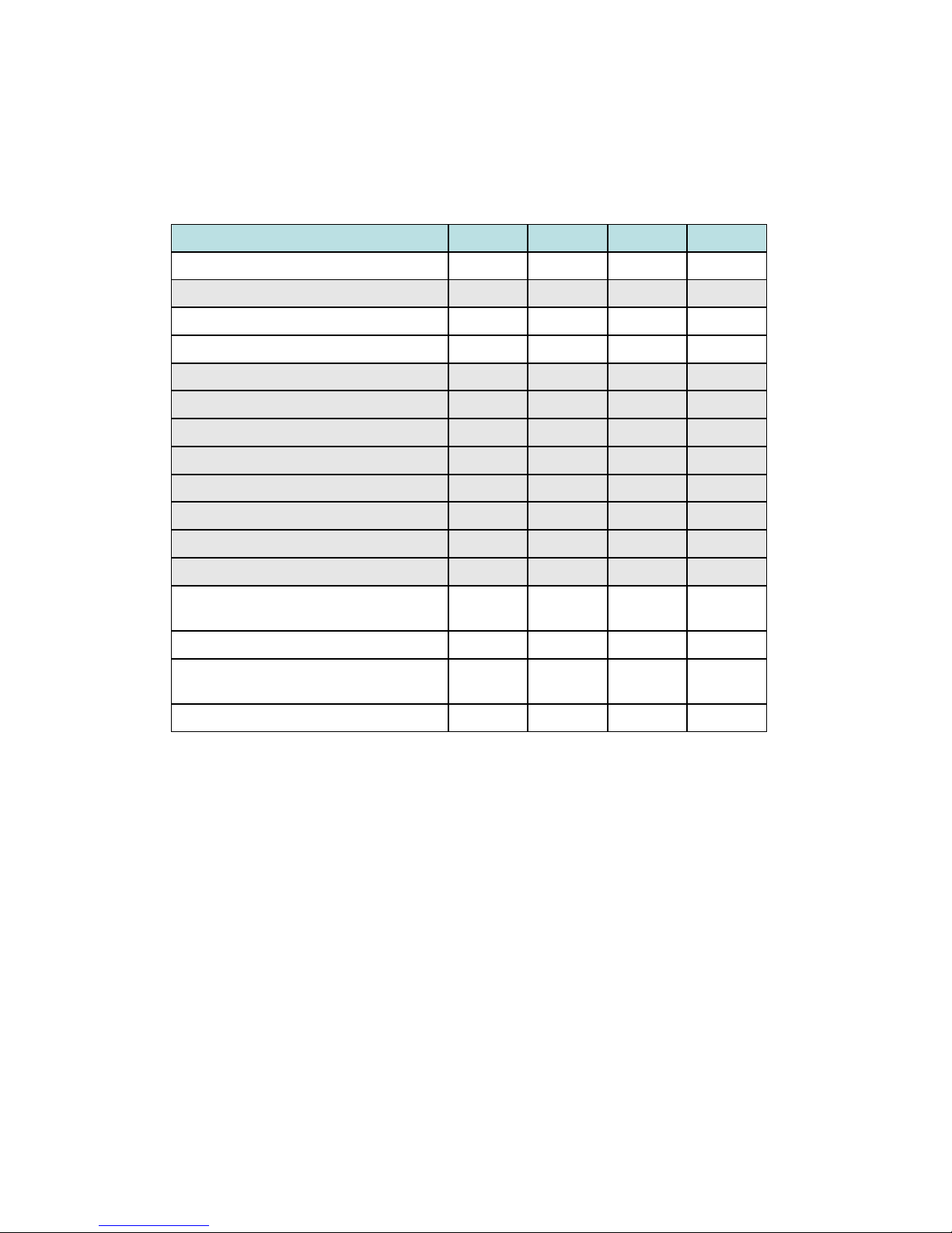
PWR 1
PWR 2
AC/HDC
Connector
Low
Voltage
DI/DO
5628G
5828G
85~264VAC
1x Standard
three-pronged AC
plug
2x DC
24/48V
2DI + 2DO
5628G-2AC/
5828G-2AC
85~264VAC
85~264VAC
2x Standard
three-pronged AC
plug
2DI + 2DO
5628G-2HDC
85~264VAC
88~370VDC
85~264VAC
88~370VDC
2x 3 pin Terminal
Block
2DI + 2DO
5628G-R/
5828G-R
85~264VAC
88~370VDC
85~264VAC
88~370VDC
6 pin Terminal
Block
1 DO
Note: The PWR 1 and PWR2 can support both 85-264VAC and 88-370VDC High Voltage
DC input. The AC connector is standard three-pronged AC connector, the High Voltage DC
connector is 3-pin terminal block represent for L, N and PE. The LDC connector is a 4 pin
terminal block for dual input.
4
1.2 Major Features
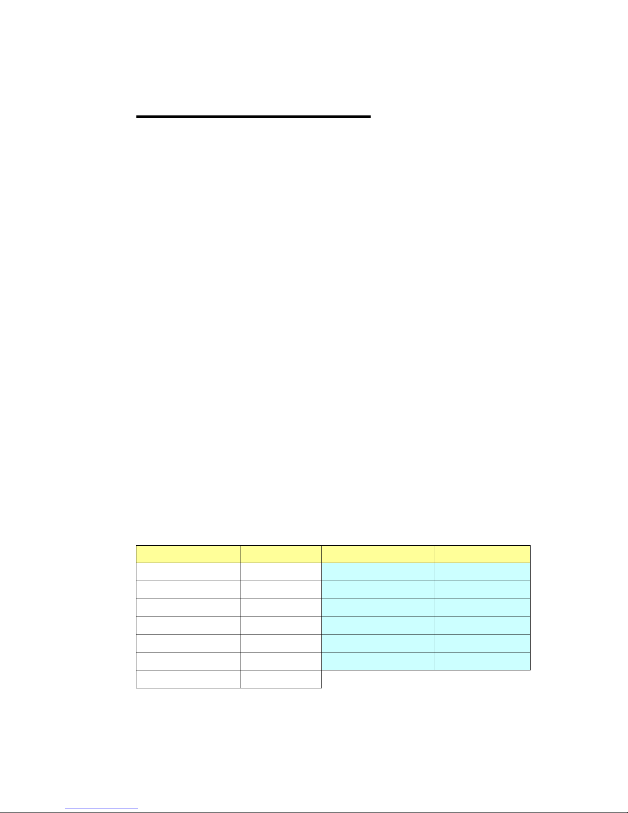
Korenix JetNet 5628G/5828G has the below different models as below.
Feature
5628G
5628G-R
5828G
5828G-R
IEC 61850-3 Design
V V V
V
Ethernet Port on the Rear
V
V
On Board free 4G combo ports
V V V
V
3 Flexible Modules
V V V
V
Max. Ring
14
14
14
14
Multiple Spanning Tree Protocol
V V V
V
256VLANs
V V V
V
8 physical priority queues
V V V
V
Private VLAN, QinQ
V V V
V
Modbus/TCP
V V V
V
Layer 2+ ACL, 802.1x
V V V
V
SNMP, LLDP & JetView Pro NMS
V V V
V
Layer 3 Unicast Routing Protocols - RIP,
OSPF
V
V
Virtual Router Redundancy Protocol
V
V
Layer 3 Multicast Routing Protocols –
DVMRP (coming soon)
V
V
Advanced PIM-DM/SM (coming soon)
V
V
The detail spec is listed in latest datasheet. Please download the latest datasheet in
Korenix Web site.
1.3 Package List
Korenix JetNet 5628G/5828G Series products are shipped with following items:
JetNet 5628G/5828G (4G Combo on board, No Fast Ethernet modules, no SFP
transceivers)
Rack Mount Kit
Console Cable
Power Cord
Quick Installation Guide
Document CD
If any of the above items are missing or damaged, please contact your local sales
representative.

5
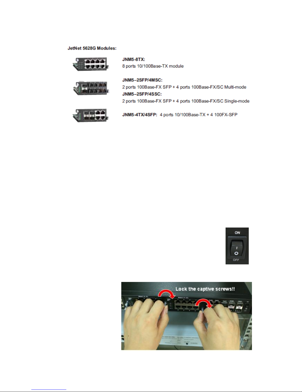
1.4 Optional Module
Additional Fast Ethernet Modules:
JNM5-8TX: 8 ports 10/100Base-TX module
JNM5-4TX/4SFP: 4 ports 10/100TX + 4 100FX-SFP Socket
JNM5–2SFP/4MSC: 2 ports 100Base-FX + 4 ports 100Base-FX/SC Multi-mode
JNM5–2SFP/4SSC: 2 ports 100Base-FX + 4 ports 100Base-FX/SC Single-mode
Notice: The system only allow Maximum 12 SC type Fiber Links within one Switch. Less
than 12 Fiber links is Korenix recommend in high temperature environment, especially
no- air condition environment.
6
2 Hardware Installation
This chapter includes hardware introduction, installation and configuration information.
Following topics are covered in this chapter:
2.1 Hardware Introduction
Dimension
Panel Layout
Bottom View
2.2 Wiring Power Inputs
2.3 Wiring Digital Input
2.4 Wiring Relay Output
2.5 Wiring Earth Ground
2.6 Choosing Fast Ethernet Module
2.7 Wiring Ethernet Ports
2.8 Wiring Fiber Ports
2.9 Wiring Gigabit Combo Ports
2.10 Wiring RS-232 console cable
2.11 Rack Mounting Installation
2.12 Safety Warming
2.1 Hardware Introduction
2.1.1 JetNet 5628G/5828G (Ethernet Ports on the Front) Series
LED
System LED
Color
Port LED
Color
PWR/AC 1, PWR/AC 2
Green On/Off
Port 1~8 (JNM5-8TX)
Green/Green Blinking
LDC 1, LDC 2 (DC Power)
Green On/Off
Port 1~8 (JNM5-4TX/4SFP)
Green/Green Blinking
RDY (System Ready)
Green On/Off
Port 1~6 (JNM5-2SFP/4MSC)
Green/Green Blinking
DI 1, DI 2 (Digital Input)
Green On/Off
Port 1~6 (JNM5-2SFP/4SSC)
Green/Green Blinking
R.M. (Ring Master)
Green On/Off
Port 25~28 (Gigabit RJ45)
Green/Green Blinking
DO 1, DO 2 (Digital Output)
Red On/Off
Port 25~28 (Gigabit SFP)
Green/Green Blinking
R.F. (Ring Failure)
Red On/Off
For one AC model, the PWR2/AC2 LED is always not light. For dual AC/HDC model, the
LDC1/2 LED is always not light.
7
Dimension
JetNet 5628G/5828G Industrial Modular Managed Ethernet Switch dimension (W x H x D)
is 44mm(H) x 431mm (W) x 376mm (D)
Panel Layout
The front panel includes 3 modular slots for Fast Ethernet Module.
4 On-Board Gigabit Combo Port which support 10/100/1000 Copper and Gigabit SFP.
Power switch is used when you want change modular or save power.
In the back of the switch, there are AC, HDC or LDC power input socket, Digital
Input/Output socket and RS232 console port.
8
2.1.1 JetNet 5628G-R/5828G-R (Ethernet Ports on the Rear) Series
LED
LED on the Front
Color
LED on the Module
Color
P1, P2 (Power LED)
Green On/Off
Port 1~8 (JNM5-8TX)
Green/Green Blinking
DO 1 (Digital Output)
Red On/Off
Port 1~8 (JNM5-4TX/4SFP)
Green/Green Blinking
R.S. (Ring Status)
Green: Ring state is normal
Green Flashing: Incorrect
configuration
Amber: Ring state is
abnormal
Amber Flashing: One of the
ring ports break has been
detected
Port 1~6 (JNM5-2SFP/4MSC)
Green/Green Blinking
Port 1-28
Green/Green Blinking
Port 1~6 (JNM5-2SFP/4SSC)
Green/Green Blinking
Note: Port 25-28 is gigabit combo port, there is no LED on the rear panel.
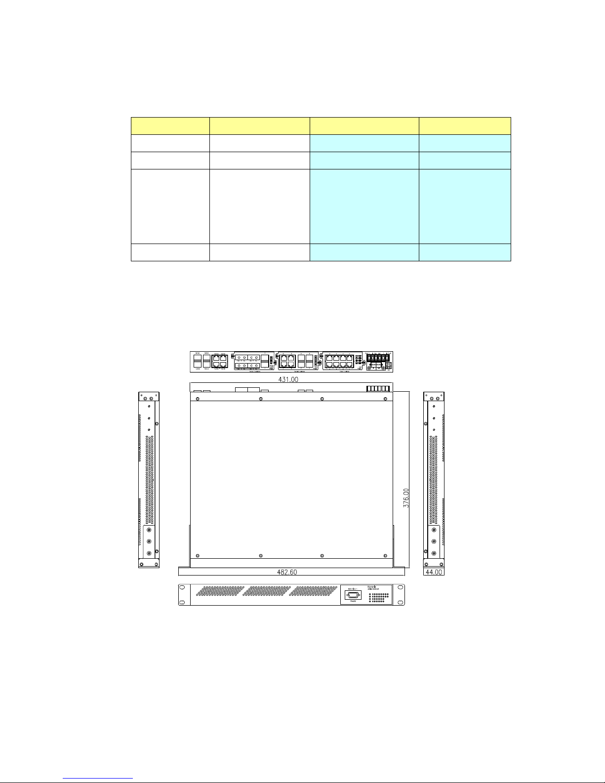
Dimension
JetNet 5628G-R/5828G-R Industrial Modular Managed Ethernet Switch dimension (W x
H x D) is 44mm(H) x 431mm (W) x 376mm (D)
Panel Layout
The front panel includes RS-232 console and LED information only.
The rear panel includes 3 modular slots for Fast Ethernet Module. 4 On-Board Gigabit
Combo Port which support 10/100/1000 Copper and Gigabit SFP. And 6-pin High
Voltage Power Input socket and 1 Digital Output socket
9
2.2 Wiring Power Inputs
JetNet 5628G/5828G provides 2 types power input, AC power input and DC power input.
The front power switch can switch off all the power input at the same time.
AC Power Input
Connect the attached power cord to the AC power input connector, the available AC
power input is range from 85-264VAC.
High Voltage Power Input
The power input support both 85-264VAC and 88-370VDC power input. Connect the
power cord to the PE for Protective Earth, L / V+ for LINE or V+, N/V- for Neutral or V-.
For high power input, tighten the wire-clamp screws to prevent DC wires from being
loosened is must.
The pin assignment sequence of JetNet 5628G-R/5828G-R is N, L, PE for Power input 1
and PE, N, L for Power Input 2.
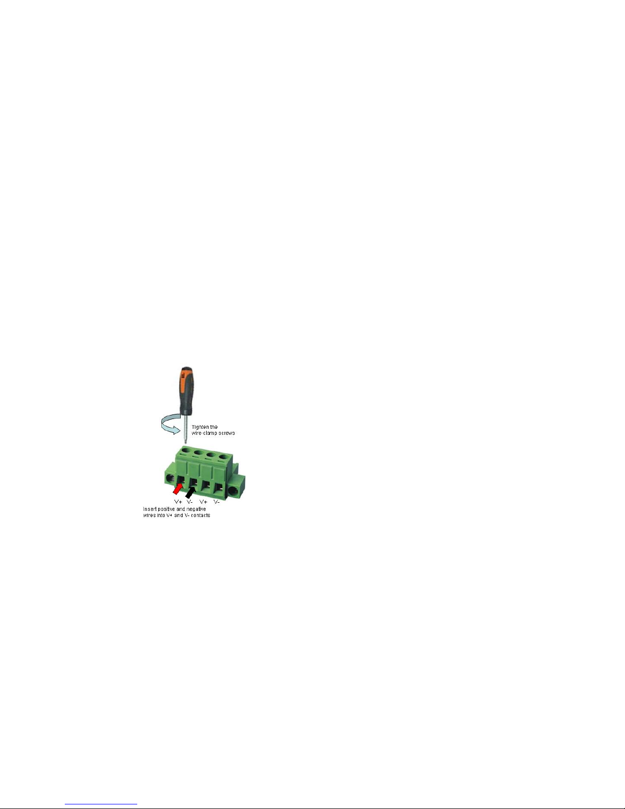
DC Power Input
Follow below steps to wire JetNet 5628G/5828G redundant DC power inputs.
1. Insert positive and negative wires into V+ and Vcontacts respectively of the terminal block
connector
2. Tighten the wire-clamp screws to prevent DC
wires from being loosened.
3. Power 1 and Power 2 support power redundancy
and polarity reverse protection functions.
Note 1: It is a good practice to turn off input and load power, and to unplug power terminal
block before making wire connections. Otherwise, your screwdriver blade can
inadvertently short your terminal connections to the grounded enclosure.
Note 2: The range of the suitable DC electric wire is from 12 to 24 AWG.
Note 3: If the 2 power inputs are connected, JetNet 5628G/5828G will be powered from
the highest connected voltage. The unit will alarm for loss of power, either PWR1 or
PWR2.
2.3 Wiring Digital Input
JetNet 5628G/5828G provides 2 digital inputs. It allows users to connect the termination
units’ digital output and manage/monitor the status of the connected unit. The Digital Input
pin can be pulled high or low; thus the connected equipments can actively drive these
pins high or low. The embedded software UI allows you to read and set the value to the
connected device.
The power input voltage of logic low is DC 0~10V. Logic high is DC 11~30V.

10
Wire the digital input just like wiring the power input introduced in chapter 2.2.
The JetNet 5628G-R/5828G-R doesn’t support Digital Input.
2.4 Wiring Digital Output
JetNet 5628G/5828G provide 2 digital outputs and JetNet 5628G-R/5828G-R provide 1
digital output, also known as Relay Output. The relay contacts are energized (open) for
normal operation and will close for fault conditions. The fault conditions include power
failure, Ethernet port link break or other pre-defined events which can be configured in
JetNet 5628G/5828G UI.
The default (without power) state of the Digital Output is normal OPEN state. The
ON/OFF state is controlled by software configuration.
The JetNet 5628G-R and JetNet 5828G-R support both OPEN and CLOSE mode.
Follow the installation guide print in the panel to wire.
Pin No.
State
1
NO (Normal Open)
2
COM
3
COM
4
NC (Normal Close)
Loosen the Digital Output screw by screw drive, then tighten the screw after digital output
wire is connected.
Note: When installed the Digital Output in your environment, remember to check the
environment protection, like Surge protection of the connected device. The digital output
contact of the JetNet 5628G/5828G do not provide high level Surge protection, this should
be protected by connected device.
2.5 Wiring Earth Ground
To ensure the system will not be damaged by noise or any electrical shock, we suggest
you to make exact connection with JetNet 5628G/5828G with Earth Ground.
For AC input, the 3 pin include V+, V- and GND. The GND pin must be connected to the
earth ground.
For High Voltage DC (HVDC) input, PE is Protective Earth pin.
For DC input, loosen the earth ground screw by screw drive; then tighten the screw after
earth ground wire is connected.
2.6 Choosing Fast Ethernet Module
The JetNet 5628G/5828G provides several types of Fast Ethernet modules. There are 8
10/100Base-TX ports, 4 100Base-FX/SC ports plus 2 100Base-FX SFP and 4
10/100Base-TX plus 4 100Base-FX modules.
11
The module type includes:
The modular design is more flexible for purchasing, less storage of stock and field
installations. Once the distance is over 100 meters, users can exchange modules without
replacing device. The 3 modules allow you connect maximum 24 10/100Base-TX Copper
ports or maximum 18 100Base-FX Fiber ports.
As purchasing the JetNet 5628G/5828G, please confirm the media type and the port
volume. Discuss the need with your customer and advise them your plan for the media
ports is the consideration before purchasing the Ethernet module.
Note: The JetNet 5628G/5828G main board can support high temperature environment.
There is no limitation to connect up to 3 x JNM5-8TX modules. Should you want connect
the Fiber modules, please check the environment temperature first. The heat from the
fiber interface is much higher than copper, using wide-temperature SFP transceiver is
recommended. Korenix requests less than 12 Fiber connections within one JetNet
5628G/5828G box when install in high temperature environment, especially no- air
condition environment. Should you need more fiber connections in one field station,
please separate them to 2 or more JetNet 5628G/5828G box.
2.7 Mounting Fast Ethernet Module
2.7.1 Power down the switch or Turn off the front power switch of the 5628G/5828G
series.
2.7.2 Unlock the front plate of the slot and plug the Fast Ethernet Module into the
socket.
2.7.3 Turn the captive screw to lock the module.
2.7.4 After locked the modules,
turn on the switch.
Note: Each time when you
plug or exchange module,
be noticed that you
should turn off the power
first.
12
2.8 Wiring Fast Ethernet Ports
JetNet 5628G/5828G includes maximum 24 RJ-45 Fast Ethernet ports. The fast Ethernet
ports support 10Base-T and 100Base-TX, full or half duplex modes. All the fast Ethernet
ports will auto-detect the signal from connected devices to negotiate the link speed and
duplex mode. Auto MDI/MDIX allows users to connect another switch, hub or workstation
without changing straight through or crossover cables.
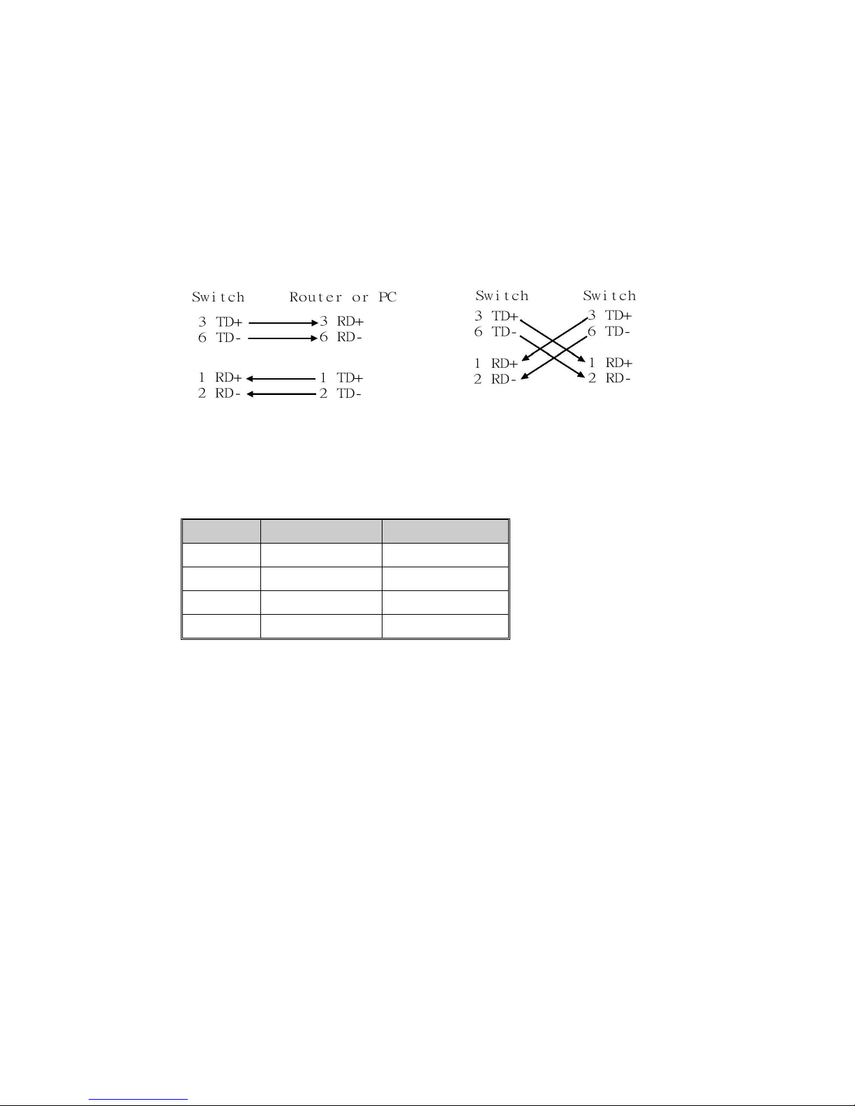
Note that crossover cables simply cross-connect the transmit lines at each end to the
received lines at the opposite end.
Straight-through Cabling Schematic
Cross-over Cabling Schematic
Note that Ethernet cables use pins 1, 2, 3, and 6 of an 8-pin RJ-45 connector. The signals
of these pins are converted by the automatic MDI-X function, as shown in the table below:
Pin MDI-X
Signals
MDI Signals
1
RD+
TD+
2
RD-
TD-
3
TD+
RD+
6
TD-
RD-
Connect one side of an Ethernet cable into any switch port and connect the other side to
your attached device. The LNK LED will light up when the cable is correctly connected.
Refer to the LED Indicators section for descriptions of each LED indicator. Always make
sure that the cables between the switches and attached devices (e.g. switch, hub, or
workstation) are less than 100 meters (328 feet).
The wiring cable types are as below.
10Base-T: 2-pair UTP/STP Cat. 3, 4, 5 cable, EIA/TIA-568 100-ohm (100m)
100 Base-TX: 2-pair UTP/STP Cat. 5 cable, EIA/TIA-568 100-ohm (100m)
1000 Base-TX: 4-pair UTP/STP Cat. 5 cable, EIA/TIA-568 100-ohm (100m)
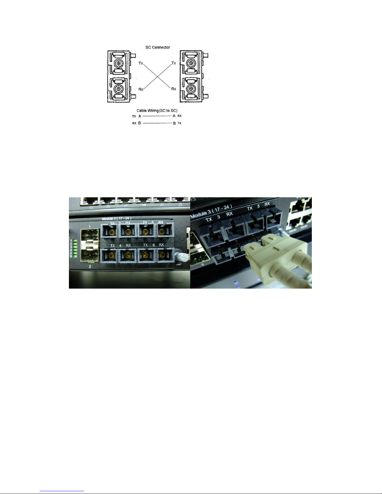
2.9 Wiring Fiber Ports
100Base-FX-SC Fiber
The automatic MDI/MDI-X crossover function does not apply to fiber connections, as
these must be crossed over manually. To connect the fiber port on one switch to the fiber
port of another switch, simply cross-connect the transmit channel at each end to the
receive channel at the opposite end as illustrated in the figure below.
13
JNM5-2SFP/4MSC and JNM5-2SFP/4SSC provides four 100Base-FX ports with SC type
connectors (in multi-mode and single mode versions). Single-mode types have greater
distance capability than multi-mode types, but single mode cable is generally more
expensive.
A fiber segment using single-mode cable must use 9/125 or 10/125 micrometer
single-mode fiber cables. For single-mode, the connection distance can be up to 30 km.
A fiber segment using multi-mode must use 50 or 62.5/125 micrometer multi-mode fiber
cables. For multi-mode, the connection distance can be up to 2 km.
Small Form-factor Pluggable (SFP)
The SFP ports accept standard MINI GBIC SFP transceiver. But, to ensure system
reliability, Korenix recommends using the Korenix certificated Gigabit SFP
Transceiver. The web UI will show Unknown vendor type when choosing the SFP which
is not certificated by Korenix. The certificated SFP transceiver includes 100Base-FX
single/multi mode, 100/Gigabit BIDI/WDM, 1000Base-SX/LX single/multi mode ranger
from 550m to 80KM.
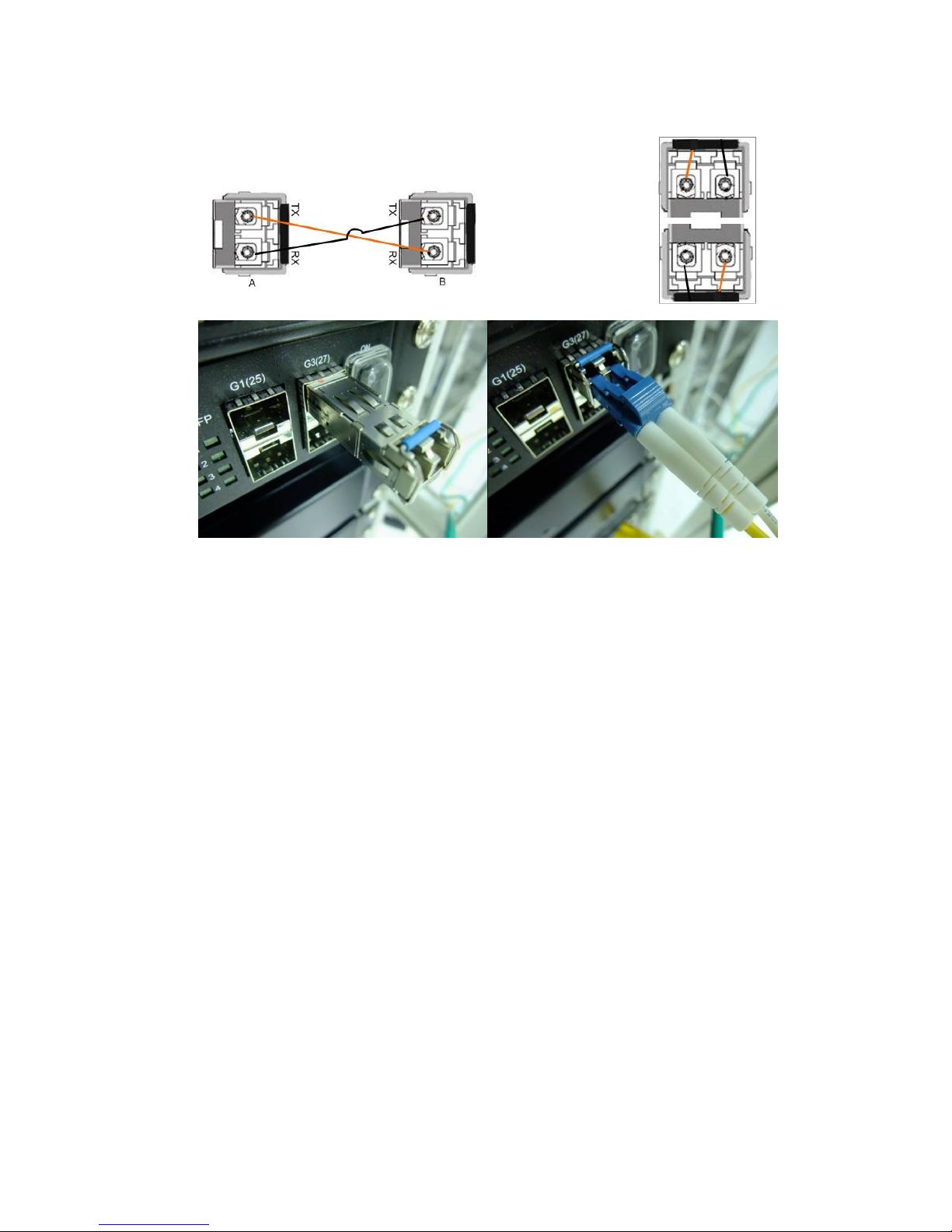
14
The way to connect the SFP transceiver is to Plug in SFP fiber transceiver fist. Cross-connect the
transmit channel at each end to the receive channel at the opposite end as
illustrated in the figure below. The SPF cage is 2x1 design, check the
direction/angle of the fiber transceiver and fiber cable when inserted.
Note: This is a Class 1 Laser/LED product. Don’t stare at the
Laser/LED Beam.
2.10 Wiring Gigabit Combo Ports
JetNet 5628G/5828G includes 4 RJ-45 Gigabit Ethernet ports. The speed of the gigabit
Ethernet port supports 10Base-T, 100Base-TX and 1000Base-TX. JetNet 5628G/5828G
also equips 4 gigabit SFP ports combo with gigabit Ethernet ports. The speed of the
gigabit SFP port supports 1000Full Duplex. The available gigabit SFP supports Gigabit
Single-mode, Multi-mode, BIDI/WDM single-mode and DDM SFP transceivers. (The
100Base-FX is not supported in gigabit combo ports.)
While connect both RJ-45 and SFP at a time, the SFP will be chosen as the active media.
2.11 Wiring RS-232 Console Cable
Korenix JetNet 5628G/5828G attaches one RS-232 DB-9 to DB-9 cable in the box.
Connect the DB-9 connector to the COM port of your PC, open Terminal tool and set up
serial settings to 9600, N,8,1. (Baud Rate: 9600 / Parity: None / Data Bit: 8 / Stop Bit: 1)
Then you can access CLI interface by console able.
Note: If you lost the cable, please contact with your sales or follow the pin assignment to
buy a new one. The Pin assignment spec is listed in the appendix.
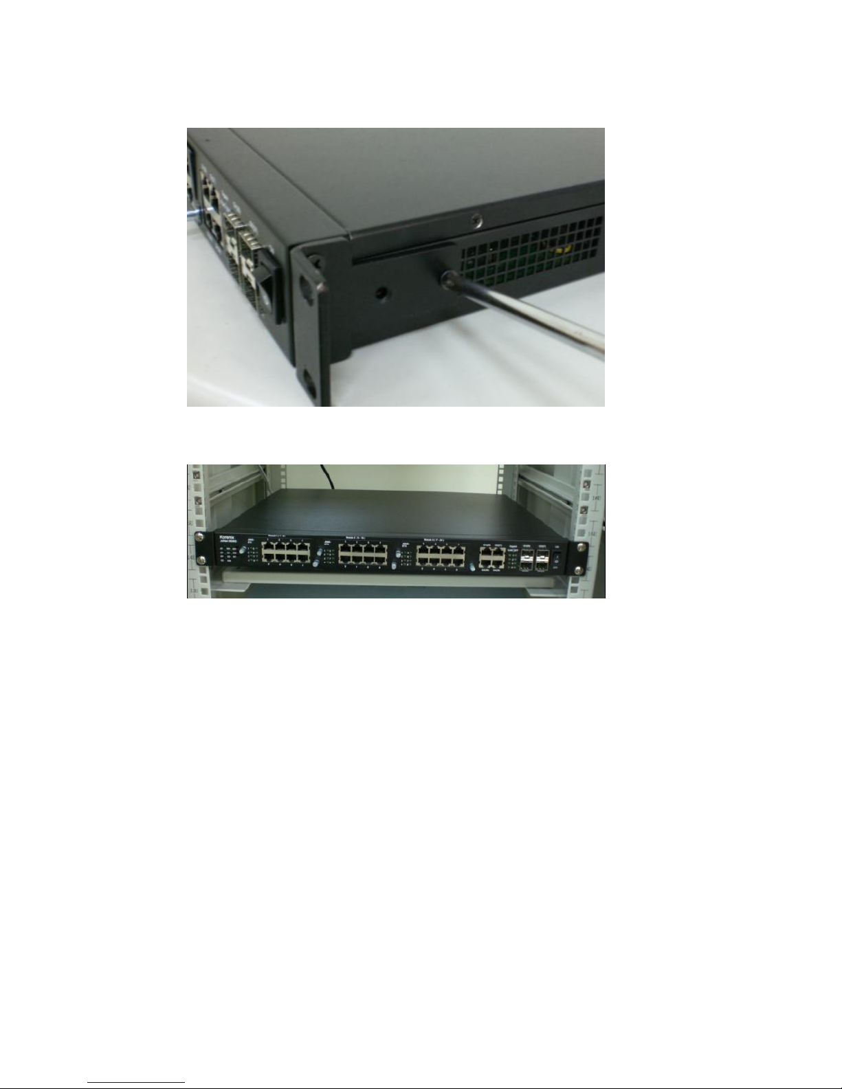
2.12 Rack Mounting Installation
The Rack Mount Kit is attached inside the package.
15
2.1.1 Attach the brackets to the device by using the screws provided in the Rack
Mount kit.
2.2.2 Mount the device in the 19’ rack by using four rack-mounting screws provided by
the rack manufacturer.
When installing multiple switches, mount them in the rack one below the other. It’s
requested to reserve 0.5U-1U free space for multiple switches installing. This is
important to disperse the heat generated by the switch.
Notice when installing:
Temperature: Check if the rack environment temperature conforms to the specified operating
temperature range.
Mechanical Loading: Do no place any equipment on top of the switch
Grounding: Rack-mounted equipment should be properly grounded.
Fiber Port limitation: Maximum 12 Fiber ports are allowed to install under the highest
temperature. Wide-Temperature SFP transceiver is always suggested.

16
2.13 Safety Warming
2.2.1 The Equipment intended for installation in a Restricted Access
Location.
2.2.2 The warning test is provided in user manual. Below is the information:
”For tilslutning af de ovrige ledere, se medfolgende installationsvejledning”.
“Laite on liitettava suojamaadoitus-koskettimilla varustettuun pistorasiaan”
„Apparatet ma tilkoples jordet stikkontakt“
”Apparaten skall anslutas till jordat uttag”

17
3 Preparation for Management
JetNet 5628G/5828G Industrial Modular Managed Switch provides both in-band and
out-band configuration methods. You can configure the switch via RS232 console cable
if you don’t attach your admin PC to your network, or if you lose network connection to
your JetNet 5628G/5828G. This is so-called out-band management. It wouldn’t be
affected by network performance.
The in-band management means you can remotely manage the switch via the network.
You can choose Telnet or Web-based management. You just need to know the device’s
IP address and you can remotely connect to its embedded HTTP web pages or Telnet
console.
Following topics are covered in this chapter:
3.1 Preparation for Serial Console
3.2 Preparation for Web Interface
3.3 Preparation for Telnet console
3.1 Preparation for Serial Console
In JetNet 5628G/5828G package, Korenix attached one RS-232 DB-9 to DB-9 console
cable. Please attach RS-232 DB-9 connector to your PC COM port, connect the other
end to the Console port of the JetNet 5628G/5828G. If you lose the cable, please follow
the console cable PIN assignment to find one. (Refer to the appendix).
1. Go to Start -> Program -> Accessories -> Communication -> Hyper Terminal
2. Give a name to the new console connection.
3. Choose the COM name
4. Select correct serial settings. The serial settings of JetNet 5628G/5828G are as
below:
Baud Rate: 9600 / Parity: None / Data Bit: 8 / Stop Bit: 1
5. After connected, you can see Switch login request.
6. Login the switch. The default username is “admin”, password, “admin”.
Booting...
Sun Jan 1 00:00:00 UTC 2006
Switch login: admin
Password:
JetNet5628G (version 0.2.25-20090414-11:04:13).
Copyright 2006-2008 Korenix Technology Co., Ltd.
Switch>
18
3.2 Preparation for Web Interface
JetNet 5628G/5828G provides HTTP Web Interface and Secured HTTPS Web Interface
for web management.
3.2.1 Web Interface
Korenix web management page is developed by JAVA. It allows you to use a standard
web-browser such as Microsoft Internet Explorer, or Mozila, to configure and interrogate
the switch from anywhere on the network.
Before you attempt to use the embedded web interface to manage switch operation,
verify that your JetNet 5628G/5828G Series Industrial Ethernet Switch is properly
installed on your network and that every PC on this network can access the switch via
the web browser.
1. Verify that your network interface card (NIC) is operational, and that your operating
system supports TCP/IP protocol.
2. Wire DC power to the switch and connect your switch to your computer.
3. Make sure that the switch default IP address is 192.168.10.1.
4. Change your computer IP address to 192.168.10.2 or other IP address which is
located in the 192.168.10.x (Network Mask: 255.255.255.0) subnet.
5. Switch to DOS command mode and ping 192.168.10.1 to verify a normal response
time.
Launch the web browser and Login.
6. Launch the web browser (Internet Explorer or Mozila Firefox) on the PC.
7. Type http://192.168.10.1 (or the IP address of the switch). And then press Enter.
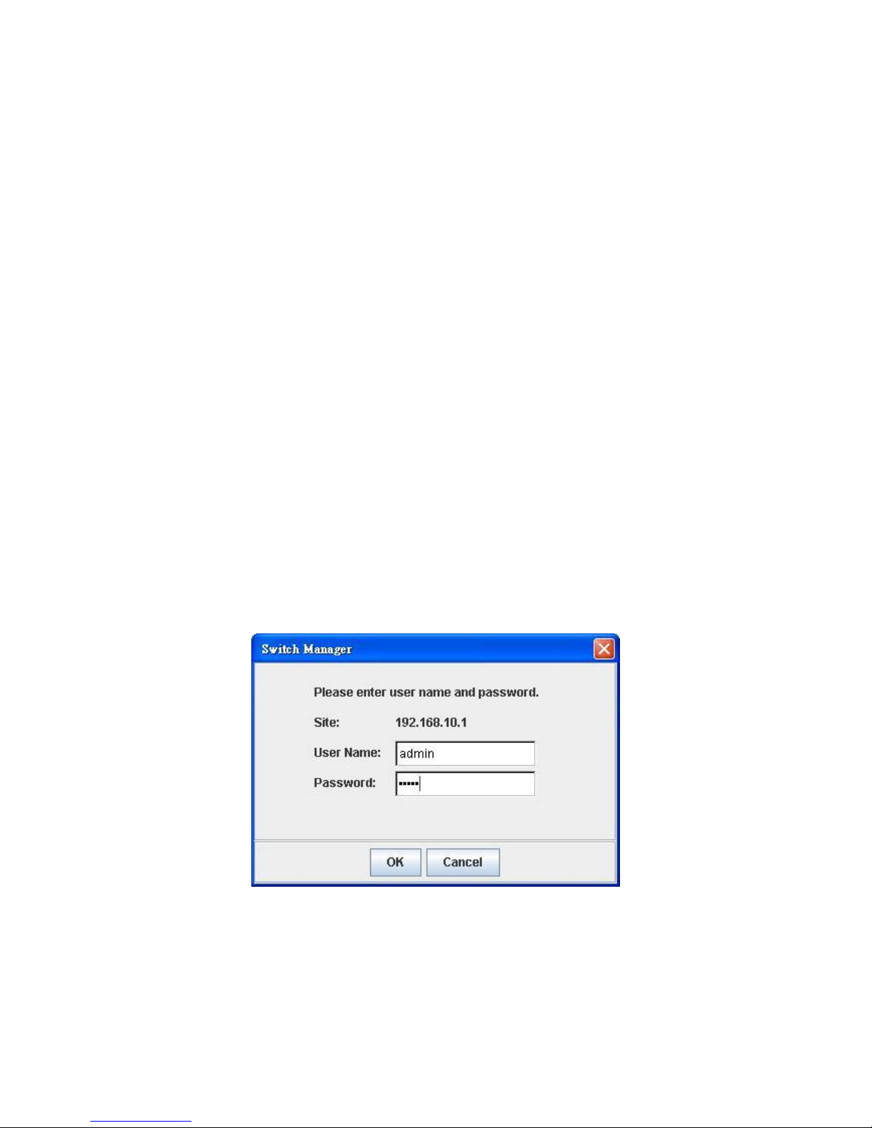
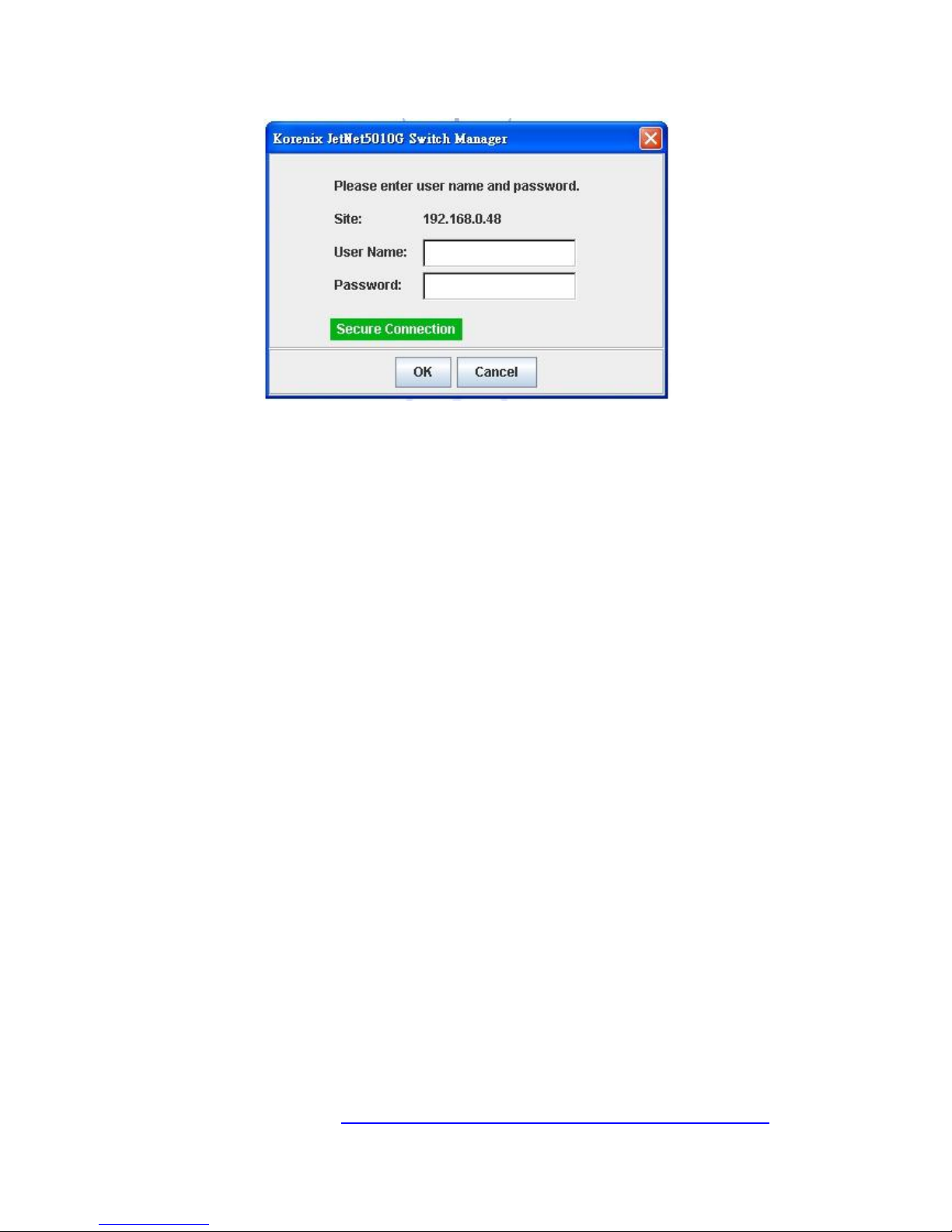
8. The login screen will appear next.
9. Key in user name and the password. Default user name and password are both
admin.
Click on Enter or OK. Welcome page of the web-based management interface will then
appear.
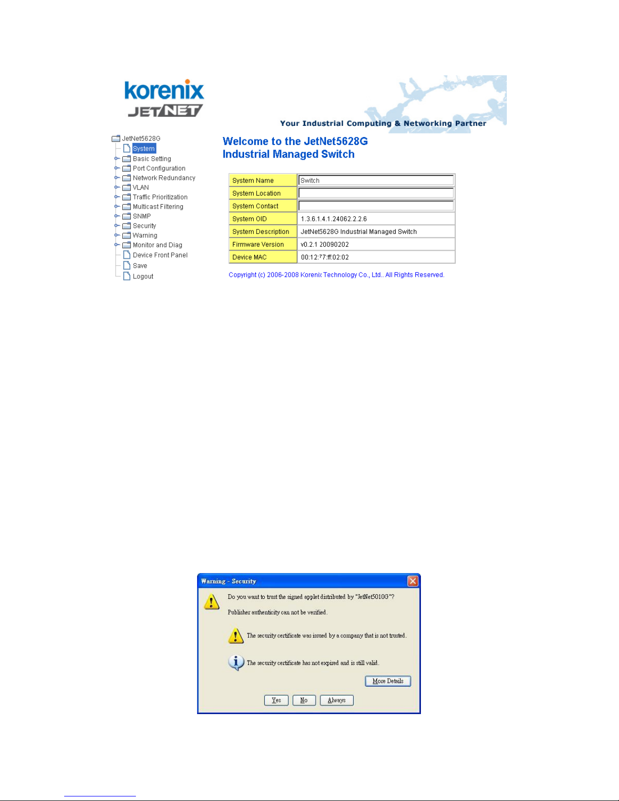
19
Once you enter the web-based management interface, you can freely change the
JetNet’s IP address to fit your network environment.
Note 1: IE 5.0 or later versions do not allow Java applets to open sockets by default.
Users have to directly modify the browser settings to selectively enable Java applets to
use network ports.
Note 2: The Web UI connection session of JetNet 5628G/5828G will be logged out
automatically if you don’t give any input after 30 seconds. After logged out, you should
re-login and key in correct user name and password again.
3.2.2 Secured Web Interface
Korenix web management page also provides secured management HTTPS login. All
the configuration commands will be secured and will be hard for the hackers to sniff the
login password and configuration commands.
Launch the web browser and Login.
1. Launch the web browser (Internet Explorer or Mozila Firefox) on the PC.
2. Type https://192.168.10.1 (or the IP address of the switch). And then press Enter.
3. The popup screen will appear and request you to trust the secured HTTPS
connection distributed by JetNet 5628G/5828G first. Press Yes to trust it.
4. The login screen will appear next.
20
5. Key in the user name and the password. The default user name and password is
admin.
6. Click on Enter or OK. Welcome page of the web-based management interface will
then appear.
7. Once you enter the web-based management interface, all the commands you see
are the same as what you see by HTTP login.
3.3 Preparation for Telnet Console
3.3.1 Telnet
Korenix JetNet 5628G/5828G supports Telnet console. You can connect to the switch by
Telnet and the command lines are the same as what you see by RS232 console port.
Below are the steps to open Telnet connection to the switch.
1. Go to Start -> Run -> cmd. And then press Enter
2. Type the Telnet 192.168.10.1 (or the IP address of the switch). And then press
Enter
3.3.2 SSH (Secure Shell)
Korenix JetNet 5628G/5828G also support SSH console. You can remotely connect to
the switch by command line interface. The SSH connection can secure all the
configuration commands you sent to the switch.
SSH is a client/server architecture while JetNet 5628G/5828G is the SSH server. When
you want to make SSH connection with the switch, you should download the SSH client
tool first.
SSH Client
There are many free, sharewares, trials or charged SSH clients you can find on the
internet. Fox example, PuTTY is a free and popular Telnet/SSH client. We’ll use this
tool to demonstrate how to login JetNet by SSH. Note: PuTTY is copyright 1997-2006
Simon Tatham.
Download PuTTY: http://www.chiark.greenend.org.uk/~sgtatham/putty/download.html
21
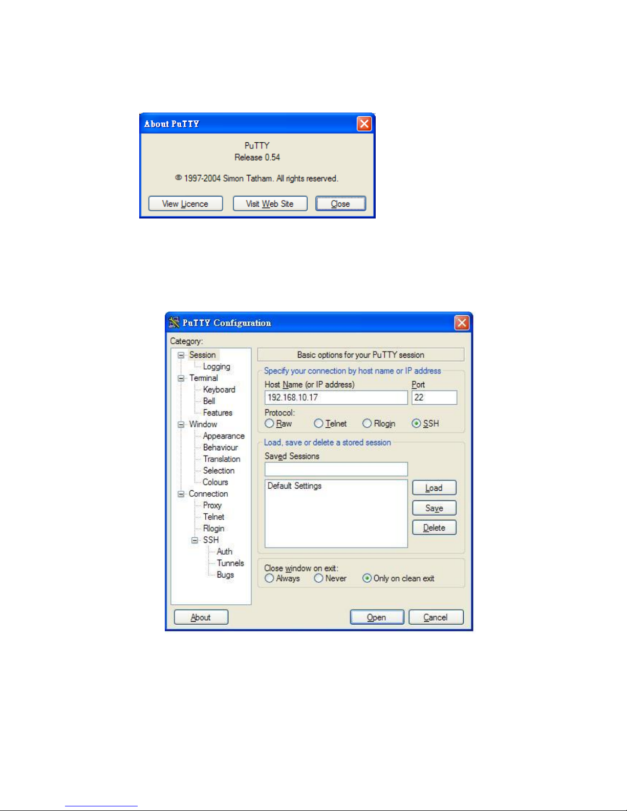
The copyright of PuTTY
Open SSH Client/PuTTY
1. In the Session configuration, enter the Host Name (IP Address of your JetNet
5628G/5828G) and Port number (default = 22). Choose the “SSH” protocol. Then
click on “Open” to start the SSH session console.
2. After click on Open, then you can see the cipher information in the popup screen.
Press Yes to accept the Security Alert.
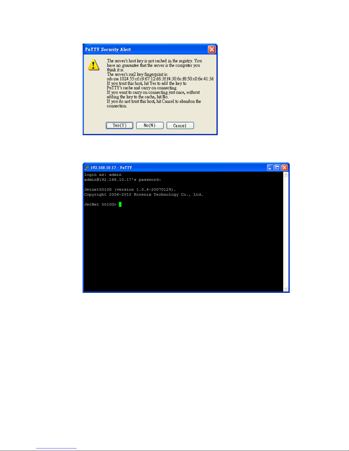
22
3. After few seconds, the SSH connection to JetNet 5628G/5828G is opened. You can
see the login screen as the below figure.
4. Type the Login Name and its Password. The default Login Name and Password are
admin / admin.
5. All the commands you see in SSH are the same as the CLI commands you see via
RS232 console. The next chapter will introduce in detail how to use command line to
configure the switch.
Note: The 5628G series is a layer 2 switch, only the IP address of the management VLAN can be
accepted. The JetNet 5828G/5828G-R is a layer 3 switch. The IP address of each VLAN/IP interface can
be added. The switch can accept multiple IP address for remote management.

23
4 Feature Configuration
This chapter explains how to configure JetNet 5628G/5828G software features. There are
four ways to access the switch: Serial console, Telnet, Web browser and SNMP.
JetNet 5628G/5828G series Industrial Managed Switch provides both in-band and
out-band configuration methods. You can configure the switch via RS232 console cable if
you don’t attach your admin PC to your network, or if you lose the network connection to
your JetNet 5628G/5828G. This is so-called out-band management. It wouldn’t be affected
by the network performance.
The in-band management means you can remotely manage the switch via the network.
You can choose Telnet or Web-based management. You just need to know the device’s IP
address. Then you can remotely connect to its embedded HTML web pages or Telnet
console.
Korenix web management page is developed by JAVA. It allows you to use a standard
web-browser such as Microsoft Internet Explorer, or Mozila, to configure and interrogate
the switch from anywhere on the network.
Note: IE 5.0 or later versions do not allow Java applets to open sockets by default. Users
have to directly modify the browser settings to selectively enable Java applets to use
network ports.
Following topics are covered in this chapter:
4.1 Command Line Interface (CLI) Introduction
4.2 Basic Setting
4.3 Port Configuration
4.4 Network Redundancy
4.5 VLAN
4.6 Private VLAN
4.7 Traffic Prioritization
4.8 Multicast Filtering
4.9 Routing (Apply to JetNet 5828G Series)
4.10 SNMP
4.11 Security
4.12 Warning
4.13 Monitor and Diag
4.14 Device Front Panel
4.15 Save
4.16 Logout

24
4.1 Command Line Interface Introduction
The Command Line Interface (CLI) is the user interface to the switch’s embedded software
system. You can view the system information, show the status, configure the switch and
receive a response back from the system by keying in a command.
There are some different command modes. Each command mode has its own access
ability, available command lines and uses different command lines to enter and exit. These
modes are User EXEC, Privileged EXEC, Global Configuration, (Port/VLAN) Interface
Configuration modes.
User EXEC mode: As long as you login the switch by CLI. You are in the User EXEC mode.
You can ping, telnet remote device, and show some basic information.
Type enable to enter next mode, exit to logout. ? to see the command list
Privileged EXEC mode: Press enable in the User EXEC mode, then you can enter the
Privileged EXEC mode. In this mode, the system allows you to view current configuration,
reset default, reload switch, show system information, save configuration…and enter the
global configuration mode.
Type configure terminal to enter next mode, exit to leave. ? to see the command list
JN5628G>
enable Turn on privileged mode command
exit Exit current mode and down to previous mode
list Print command list
ping Send echo messages
quit Exit current mode and down to previous mode
show Show running system information
telnet Open a telnet connection
traceroute Trace route to destination
Switch#
archive manage archive files
clear Reset functions
clock Configure time-of-day clock
configure Configuration from vty interface
copy Copy from one file to another
debug Debugging functions (see also 'undebug')
disable Turn off privileged mode command
end End current mode and change to enable mode
exit Exit current mode and down to previous mode
list Print command list
more Display the contents of a file
no Negate a command or set its defaults
ping Send echo messages
quit Exit current mode and down to previous mode
reboot Reboot system
reload copy a default-config file to replace the current one
show Show running system information
telnet Open a telnet connection
terminal Set terminal line parameters
traceroute Trace route to destination
write Write running configuration to memory, network, or terminal

25
Global Configuration Mode: Press configure terminal in privileged EXEC mode. You
can then enter global configuration mode. In global configuration mode, you can configure
all the features that the system provides you.
Type interface IFNAME/VLAN to enter interface configuration mode, exit to leave. ? to
see the command list.
Available command lists of global configuration mode.
(Port) Interface Configuration: Press interface IFNAME in global configuration mode.
You can then enter interface configuration mode. In this mode, you can configure port
settings.
The port interface name for fast Ethernet port 1 is fa1,… fast Ethernet 7 is fa7, gigabit
Ethernet port 25 is gi25.. gigabit Ethernet port 28 is gi28. Type interface name accordingly
when you want to enter certain interface configuration mode.
Type exit to leave.
Type ? to see the command list
Switch# configure terminal
Switch(config)#
access-list Add an access list entry
administrator Administrator account setting
arp Set a static ARP entry
clock Configure time-of-day clock
default Set a command to its defaults
end End current mode and change to enable mode
exit Exit current mode and down to previous mode
gvrp GARP VLAN Registration Protocol
hostname Set system's network name
interface Select an interface to configure
ip IP information
lacp Link Aggregation Control Protocol
list Print command list
log Logging control
mac Global MAC configuration subcommands
mac-address-table mac address table
mirror Port mirroring
no Negate a command or set its defaults
ntp Configure NTP
password Assign the terminal connection password
qos Quality of Service (QoS)
relay relay output type information
smtp-server SMTP server configuration
snmp-server SNMP server
spanning-tree spanning tree algorithm
super-ring super-ring protocol
trunk Trunk group configuration
vlan Virtual LAN
warning-event Warning event selection
write-config Specify config files to write to

26
Available command lists of the global configuration mode.
(VLAN) Interface Configuration: Press interface VLAN VLAN-ID in global configuration
mode. You can then enter VLAN interface configuration mode. In this mode, you can
configure the settings for the specific VLAN.
The VLAN interface name of VLAN 1 is VLAN 1, VLAN 2 is VLAN 2…
Type exit to leave the mode. Type ? to see the available command list.
The command lists of the VLAN interface configuration mode.
Switch(config)# interface vlan 1
Switch(config-if)#
description Interface specific description
end End current mode and change to enable mode
exit Exit current mode and down to previous mode
ip Interface Internet Protocol config commands
list Print command list
no Negate a command or set its defaults
quit Exit current mode and down to previous mode
shutdown Shutdown the selected interface
Switch(config)# interface fa1
Switch(config-if)#
acceptable Configure 802.1Q acceptable frame types of a port.
auto-negotiation Enable auto-negotiation state of a given port
description Interface specific description
duplex Specify duplex mode of operation for a port
end End current mode and change to enable mode
exit Exit current mode and down to previous mode
flowcontrol Set flow-control value for an interface
garp General Attribute Registration Protocol
ingress 802.1Q ingress filtering features
lacp Link Aggregation Control Protocol
list Print command list
loopback Specify loopback mode of operation for a port
mac MAC interface commands
mdix Enable mdix state of a given port
no Negate a command or set its defaults
qos Quality of Service (QoS)
quit Exit current mode and down to previous mode
rate-limit Rate limit configuration
shutdown Shutdown the selected interface
spanning-tree spanning-tree protocol
speed Specify the speed of a Fast Ethernet port or a Gigabit
Ethernet port.
switchport Set switching mode characteristics
 Loading...