

Korenix JetNet 5428G Series, JetNet 5428G-2DC, JetNet 5428G-AC Quick Installation Manual
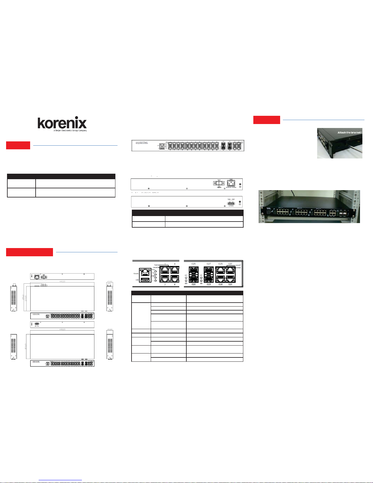
Mount the Switch to 19’’ rack
1. Attach the brackets to the device by using
the screws provided in the Rack Mount kit.
2. Mount the device in the 19’’ rack by using
four rack-mounting screws provided by the
rack manufacturer.
3. When installing multiple switches, mount
them in the rack one below the other.
Note: Check if the rack environment temperature conforms to the specified
operating temperature range. Do not place any equipment on top of the switch
and please properly grounded.
JetNet 5428G Series In dustr ial 24FE+4G Gi gabit Manage d E the rn et Switch
Quick Installation Guide V1.0
Overview
Interface Introduction
Installation
Front-Panel Components
The front panel includes RJ-45 based RS-232 console port, USB port, System
& port LEDs, Gigabit Ethernet port interfaces and Gigabit combo Port
interfaces.
Back-Panel Components
The back panel of the JetNet 5428G-AC consists of 1 AC power inputs and 1
relay output. The back panel of the JetNet 5428G-2DC consists of 2 DC
power inputs.
JetNet 5428G-AC:
JetNet 5428G-2DC:
The JetNet 5428G Series is a 19-inch Industrial 24FE+4G Gigabit Managed
Ethernet Switch equipped 2 4 100TX, 4 100/1000 RJ-45/SFP combo ports.
JetNet 5428G is designed as a fan-less rackmount switch with low power
consumption and wide operating temperature.
Package Check List
` The Rack Mount Managed Ethernet Switch
` Console cable
` Rack Mount kit
` Power Cord (Depend on Country, JetNet 5428G-2DC no Power Cord)
` QIG
LED Indicators
Model Name Description
JetNet 5428G-AC
24 100TX, 4 100/1000 RJ-45/SFP combo ports, Ind. Gigabit
Managed Ethernet Switch,-40~75°C, AC power
JetNet 5428G-2DC
24 100TX, 4 100/1000 RJ-45/SFP combo ports, Ind. Gigabit
Managed Ethernet Switch,-40~75°C, dual DC power
LED Color
Function
Alarm
Red
Power failure, port failure, ping failure,
login failure, RSR topology change
R.S.
Lit Green MSR in normal state
Lit Yellow MSR in abnormal state
Not Lit MSR function not active
Flashes Green
Incorrect configuration of MSR, ex. ring
not connected to ring port
Flashes Yellow
The break has been detected to be
local to one of the ports
PWR
Green Power (AC/DC) on
Sys
Green System on
1-
24 10/100
Copper
Lit Green/Flashes Green
Link/Activity
Lit Yellow
Duplex
G25-G28
Giga SFP
Lit Green/Flashes Green
Link/Activity
G25-G28
Giga Copper
Lit Green/Flashes Green
Link/Activity
Yellow On/Off
1000Mbps/(10/100Mbps)
Power the unit and connect to network Cable
Wiring Power Inputs
AC Power Input: connect the attached power cord to the AC power input
connector, the available AC power input is range from 90-264VAC.
DC Power Input: the suggested power input is 24VDC or 48VDC, the
available range is from 18-75VDC.
Follow below steps to wire JetNet 5428G-2DC redundant DC power inputs.
1. Insert positive and negative wires into V+ and V- contacts respectively of
the terminal block connector.
2. Tighten the wire-clamp screws to prevent DC wires from being loosened.
3. DC1 and DC2 support polarity reverse protection functions.
Wiring Digital Output
JetNet 5428G-AC provides 1 digital output, also known as relay output. The
relay contacts are energized (open) for normal operation and will close for fault
conditions. The fault conditions include power failure, Ethernet port link break
or other pre-defined events which can be configured in JetNet 5428G UI.
Wiring Earth Ground
To ensure the system will not be damaged by noise or any electrical shock, we
suggest you to make exact connection with JetNet 5428G with earth ground.
For AC input, the 3 pin include V+, V- and GND. The GND pin must be
connected to the earth ground.
For DC input, loosen the earth ground screw by screw drive; then tighten the
screw after earth ground wire is connected.
Model Name Back-Panel Components
JetNet 5428G-AC 1 AC power inputs and 1 relay output.
JetNet 5428G-2DC 2 DC power inputs.
JetNet
5428
G
AC
:
J
Dimension
JetNet 5428G Industrial 24FE+4G Gigabit Managed Ethernet Switch
dimension (H x W x D) is 43.8mm (H) x 440mm (W) x 170mm (D).
JetNet 5428G-AC
JetNet 5428G-2D C

Wiring Gigabit Combo Ports
JetNet 5428G series includes 24 RJ-45 Fast Ethernet ports. The speed of the
Gigabit Ethernet port supports 10Base-T and 100Base-TX. JetNet 5428G
series equips 4 Gigabit SFP ports combo with Gigabit Ethernet RJ-45 ports.
The speed of the SFP port supports 100MB and 1000MB Full Duplex. The
available Gigabit SFP supports Gigabit Single-mode, Multi-mode,
BIDI/WDM single-mode SFP transceivers.
While the SFP transceiver is plugged, the fiber port has higher priority than
copper port and moved to the fiber mode automatically.
Wiring RS-232 Console Cable
Korenix JetNet 5428G attaches one RS-232 cable in the box. Connect the DB9 connector to the COM port of your PC, open terminal tool and set up serial
settings to 9600, N,8,1. (Baud Rate: 9600 / Parity: None / Data Bit: 8 / Stop
Bit: 1) Then you can access CLI interface by console cable.
Note: If you lost the cable, please contact with your sales or follow the pin
assignment to buy a new one.
5 Years Warranty
Each of Korenix’s product is designed, produced, and tested with high
industrial standard. Korenix warrants that the product(s) shall be free from
defects in materials and workmanship for a period of five (5) years from the
date of delivery prov ided that the product was properly installed and used.
This warranty is voided if defects, malfunctions or failures of the warranted
product are caused by damage resulting from force measure (such as floods,
fire, etc.), other external forces such as power disturbances, over spec power
input, or incorrect cabling; or the warranted product is misused, abused, or
operated, altered and repaired in an unauthorized or improper way.
Attention! To avoid system damage caused by sparks, please DO NOT
plug in power connector when power is on.
The product is in compliance with Directive 2002/95/EC and 2011/65/EU of
the European Parliament and of the Council of 27 January 2003 on the
restriction of the use of certain hazardous substances in electrical and
electronics equipment (RoHS Directives & RoHS 2.0)
Korenix Customer Service
KorenixCARE is Korenix Technology’s global service center, where our
professional staffs are ready to answer your questions at any time.
Email address of Korenix Global Service Center: KoreCARE@korenix.com
Support
Korenix JetNet 5428G attaches one RS-232 cable in the box. Connect the DB9 connector to the COM port of your PC, open Terminal tool and set up serial
settings to 9600, N,8,1. (Baud Rate: 9600 / Parity: None / Data Bit: 8 / Stop
Bit: 1) Then you can access CLI interface by console cable.
Note: If you lost the cable, please contact with your sales or follow the pin
assignment to buy a new one.
Preparation for console management
Attach the RS-232 DB9 connector to your PC’s COM port. Connect the RJ-45
based RS-232 connector to the console port of the JetNet 5428G.
1. Go to Start ۀ Program ۀ Accessories ۀ Communication ۀ Hyper Terminal
2. Give a name to the new console connection.
3. Choose the COM name, and select the correct serial settings. The serial
settings of the JetNet 5428G are as below:
Baud Rate: 9600 / Parity: None / Data Bit: 8 / Stop Bit: 1
4. After connected, you can see Switch login request. Type the username and
password then you can login. The default username is “admin”, password is
“admin”.
5. Follow the manual to configure the software features.
Preparation for Web management
Before you attempt to use the embedded web interface to manage switch
operation, verify that your JetNet 5428G is properly installed on your network
and that every PC on this network can access the switch via the web browser.
1. Launch the web browser on the PC.
2. Type http://JetNet 5428G_IP_Address (The default IP address is
192.168.10.1.) then press Enter.
3. The login screen will appear next. Key in the user name and the password.
The default user name and password is admin/admin.
4. Click OK, and then the Home page of the web-based management interface
will appear.
5. At the left column of the web management interface is the software function.
The right column lists the available settings. The top column indicates the front
panel and shows the link status of each interface.
Preparation for Telnet management
Go to Start ۀ Program ۀ Accessories ۀ DOS Prompt, Type Telnet 192.168 .10.1
(Default IP Address) then press Enter.
Korenix Technology Co., Ltd.
(A Beijer Electronics Group Company)
Tel:+886-2-89111000
Fax:+886-2-29123328
Business service:sale s@ko reni x.com
Customer service:koreCARE@korenix.com
www.korenix.com
CPQ000N5428001
Patent No. (Taiwan):
Granted Invention: I 313547
Granted Invention: I 321415
Granted Invention: I 344766
Granted Invention: I 346480
Granted Invention: I 356616
Granted Invention: I 364684
Granted Invention: I 376118
Granted Invention: I 393317
Granted Invention: I 398066
Granted Invention: I 398125
Granted Invention: I 459757
Utility Model: M 339841
Utility Model: M 339840
Wiring Gigabit Ethernet Ports
JetNet 5428G includes 4 RJ-45 Gigabit Ethernet ports. The Gigabit Ethernet
ports support 100Base-TX and 1000Base-TX, full or half duplex modes. All
the Gigabit Ethernet ports will auto-detect the signal from connected devices
to negotiate the link speed and duplex mode. Auto MDI/MDIX allows users
to connect another switch, hub or workstation without changing straight
through or crossover cables.
Note that crossover cables simply cross-connect the transmit lines at each end
to the received lines at the opposite end.
Wiring Fiber Ports
The SFP ports accept standard Gigabit MINI GBIC SFP transceiver. But, to
ensure system reliability, Korenix recommends using the Korenix certificated
Gigabit SFP Transceiver. The web UI will show unknown vendor type when
choosing the SFP which is not certificated by Korenix. The certificated SFP
transceiver includes 100Base-FX single/multi mode, 100/Gigabit BIDI/WDM,
1000Base-SX/LX single/multi mode ranger from 550m to 80KM.
The way to connect the SFP transceiver is to plug in SFP fiber transceiver fist.
Cross-connect the transmit channel at each end to the receive channel at the
opposite end as illustrated in the figure below. The SPF cage is 2x1 design,
check the direction/angle of the fiber transceiver and fiber cable when inserted.
Note: This is a Class 1 Laser/LED product. Don’t look into the Laser/LED
Beam.
Device Management
 Loading...