

Korenix JetNet 3018G, JetNet 5012G, JetNet 5018G, JetNet 4518, JetNet 5018G 2.0 User Manual

1
Korenix
JetNet 3018G/4518/5012G/5018G/5018G 2.0
Industrial Managed Ethernet Switch
User Manual
Manual v1.4
Firmware v1.3
July, 2012
www.korenix.com

2
Korenix
JetNet 3018G/4518/5012G/5018G/5018G 2.0
Industrial Managed Ethernet Switch
User Manual
Copyright Notice
Copyright 2006-2012 Korenix Technology Co., Ltd.
All rights reserved.
Reproduction in any form or by any means without permission is prohibited.

3
Federal Communications Commission (FCC) Statement
This equipment has been tested and found to comply with the limits for a Class A digital device,
pursuant to Part 15 of the FCC Rules. These limits are designed to provide reasonable
protection against harmful interference when the equipment is operated in a commercial
environment. This equipment generates, uses, and can radiate radio frequency energy and, if
not installed and used in accordance with the instruction manual, may cause harmful
interference to radio communications. Operation of this equipment in a residential area is likely
to cause harmful interference in which case the user will be required to correct the interference
at his expense.
The user is cautioned that changes and modifications made to the equipment without approval
of the manufacturer could void the user’s authority to operate this equipment.

Index
1 Introduction ..................................................................................................................... 1
1.1 Overview .............................................................................................................. 1
1.2 Major Features ..................................................................................................... 3
1.3 Package List ........................................................................................................ 3
2 Hardware Installation ...................................................................................................... 4
2.1 Hardware Introduction.......................................................................................... 4
2.2 Wiring Power Inputs ............................................................................................. 7
2.3 Wiring Digital Output ............................................................................................ 7
2.4 Wiring Earth Ground ............................................................................................ 7
2.5 Wiring Fast Ethernet Ports ................................................................................... 8
2.6 Wiring Fiber Ports ................................................................................................ 8
2.7 Wiring Combo Ports ............................................................................................. 9
2.8 Wiring RS-232 Console Cable ............................................................................. 9
2.9 DIN-Rail Mounting Installation ........................................................................... 10
2.10 Wall Mounting Installation ................................................................................... 11
2.11 Safety Warming .................................................................................................. 12
3 Preparation for Management ....................................................................................... 14
3.1 Preparation for Serial Console ........................................................................... 14
3.2 Preparation for Web Interface ............................................................................ 15
3.3 Preparation for Telnet Console .......................................................................... 17
4 Feature Configuration .................................................................................................. 20
4.1 Command Line Interface Introduction ................................................................ 21
4.2 Basic Setting ...................................................................................................... 26
4.3 Port Configuration .............................................................................................. 45
4.4 Network Redundancy ......................................................................................... 54
4.5 VLAN .................................................................................................................. 71
4.6 Private VLAN ..................................................................................................... 81
4.7 Traffic Prioritization ............................................................................................ 88
4.8 Multicast Filtering ............................................................................................... 93
4.9 SNMP ................................................................................................................. 99
4.10 Security ............................................................................................................ 103
4.11 Warning ............................................................................................................. 116
4.12 Monitor and Diag .............................................................................................. 125
4.12 Device Front Panel ............................................................................................. 133
4.13 Save to Flash ................................................................................................... 134
4.14 Logout .............................................................................................................. 135
5 Appendix ...................................................................................................................... 136
5.1 Korenix SFP family .......................................................................................... 136
5.2 Korenix Private MIB ......................................................................................... 138
5.3 ModBus TCP /IP ....................................................................................... 139
5.4 Revision History ....................................................................................... 150
5.5 About Korenix .................................................................................................. 151

1
1 Introduction
Welcome to Korenix JetNet 3018G/4518/5012G/5018G/5018G v2.0 Series Industrial
Managed Ethernet Switch User Manual. Following models are applied to this document.
JetNet 3018G Industrial 16+2G Gigabit Ethernet Switch
JetNet 4518 Industrial 18-port Managed Fast Ethernet Switch
JetNet 5012G Industrial 8+4G Gigabit Managed Ethernet Switch
JetNet 5018G Industrial 16+2G Gigabit Managed Ethernet Switch
JetNet 5018G 2.0 Industrial 16+2G Gigabit Managed Ethernet Switch
Following topics are covered in this chapter:
1.1 Overview
1.2 Major Features
1.3 Package Checklist
1.1 Overview
The JetNet 3018G/4518/5012G/5018G/5018G v2.0, the Korenix Industrial Ethernet
Switches, are specially designed for industrial environments requesting support of high access
ports or multiple Gigabit ports. With fewer unit installation capability, the access ports share
wider on-chip backplane, faster local transmission latency, efficient upstream transmission.
The summary of the model list are as below. The JetNet 3018G is gigabit plug-and-play
Ethernet switch. The JetNet 4518/5012G/5018G/5018G v2.0 is managed switch which
supports abundant software features and can be managed through a single management
agent. You can refer to the chapter 3 and 4 for software management.
Model
Name
10/100
Base-TX
10/100/1000
Base-T
100BaseFX SFP
1000
Base-X SFP
Note
JetNet
3018G
16
2 (Combo
with SFP)
-
2
Unmanaged
switch.
Check chapter 1,
2 and 5.
JetNet
4518
18
2 (Combo
Port 17,18)
Managed Switch.
Check chapter 1,
2, 3, 4 and 5.
All the models
use different
firmware file.
JetNet
5012G
8
2 (Combo
with SFP)
4
JetNet
5018G
16
2 (Combo
with SFP)
2
JetNet
5018G 2.0
16
2 (Combo
with SFP)
2 (100M+1000M SFP)

2
The JetNet 3018G equips with 16 ports 10/100TX Fast Ethernet ports and 2 ports
1000Base-T/Gigabit SFP combo ports. The SFP ports accept all type of Gigabit SFP
transceivers, such as Gigabit SX, LX, LHX, ZX and XD for several connections and distances.
The on board gigabit port of the JetNet 3018G always acts as uplink port or server port, they
are much important than other ports. The JetNet 3018G provides 2 Digital Output to indicate
the alarm when gigabit port link failure. Additionally, the JetNet 3018G supports Jumbo frame,
up to 9,216 bytes packet size for large size file transmission, pre-configured QoS policy to
forward prioritized packets without any problem.
The JetNet 4518 is equipped with 16 10/100Base-TX Fast Ethernet ports and 2
10/100Base-TX/ 100Base-FX SFP combo ports. The SFP ports accept all types of 100M SFP
transceivers. The switch is high access ports switch, the 2 SFP ports help form 100M Fiber
Ring, this is especially apply to the low data bandwidth request applications.
The JetNet5012G, the 8+4G Industrial Managed Ethernet Switch, is equipped with 8
10/100TX Fast Ethernet ports, 2 Gigabit SFP and 2 Gigabit RJ-45/SFP combo ports. The SFP
ports accept all types of Gigabit SFP transceivers, including Gigabit SX, LX, LHX, ZX and XD
for several connections and distances. The copper interface of the 2 Gigabit combo ports
supports 10M,100M or 1000M speed. The switch can work as 8+4G, 7+3G or 10+2G switch.
Besides, the speed is auto-negotiated or software configured and all the port types have
non-blocking and wire-speed switching capability. The 8+4G design allows aggregating up to 4
100M rings plus 2 Gigabit rings, which is a unique and Korenix patent protected ring
technology.
The JetNet 5018G is equipped with 16 10/100TX Fast Ethernet ports and 2 10/100/
1000Base-T/Gigabit SFP combo ports. The SFP ports accept all types of Gigabit SFP
transceivers, including Gigabit SX, LX, LHX, ZX and XD for several connections and distances.
The JetNet 5018G 2.0 is the enhanced version of the JetNet 5018G, the SFP port of the
JetNet 5018G v2.0 can support both 100M and Gigabit SFP. The software can identify the
speed of the inserted SFP transceiver.
The embedded software of JetNet 4518/5012G/5018G/5018G 2.0 supports RSTP and
Multiple Super Ring technology for ring redundancy protection. Besides, JetNet
4518/5012G/5018G/5018G v2.0 supports full layer 2 management features, such as the VLAN,
IGMP Snooping, LACP for network control, SNMP, LLDP for network management. The
secured access is protected by Port Security, 802.1x and flexible Layer 2/4 Access Control List.
The switch can work with JetView Pro, the Korenix patented Industrial Innovation Network
Management system which can draw the network topology, automatically update ring and port
status, remotely manage the switch or monitor its status through LLDP and SNMP protocols.
With JetNet 4518/5012G/5018G/5018G 2.0, you can fulfill the technicians’ needs of having the
best solution for the industrial Ethernet infrastructure.

3
1.2 Major Features
The following are the common major features:
• Auto Gigabit SFP transceiver detection (JetNet 5012G/5018G/5018G v2.0.0)
• Auto 100M SFP transceiver detection (JetNet 4518/5018G v2.0.0)
• Non-Blocking Switching Performance, high backplane single chip solution
• Jumbo Frame up to 9,216 byte
• Dual 24V (12-48V) DC power inputs
• 2 Relay Outputs indicate Gigabit port Link Failure (JetNet 3018G) or configured other
failures by software (JetNet 4518/5012G/5018G/5018G v2.0.0)
• IEEE 802.1p Quality of Service (QoS) compliant (JetNet 3018G, the Tag Priority ID is
as following: Higher (6,7), High (4,5), Low (0,3), Lowest (1,2))
• Rigid Aluminum Case complies with IP31
• -25~70℃ operating temperature(3018G/5012G/5018G), -40~70℃ operating
temperature(5012G-w/5018G-w); -40~75℃ operating temperature (JetNet 4518)
Software Features applied to JetNet 4518/5012G/5018G/5018G v2.0.0:
• Korenix Multiple Super Ring pattern aggregates multiple rings within one unit
• IEEE 1588 Precision Time Protocol for precise time synchronization
• RSTP/STP, 256 802.1Q VLANs, QoS and up to 6/8 trunk groups
• IGMP Snooping, GMRP Rate Control for multicast message management
• LLDP for network topology live update
• SNMP V1/V2c/V3, RMON for remote management
• Works with JetView Pro Network Management software
• Modbus TCP/IP client for Factory Automation (new feature in firmware v1.3)
• Multiple language for Web user interface (new feature in firmware v1.3)
• Advanced Security supports IP/Port Security, 802.1x and Access Control List
Note: The detail spec is listed in latest datasheet. Please download the latest
datasheet in Korenix Web site.
1.3 Package List
The JetNet 3018G/4518/5012G/5018G/5018G v2.0.0 products are shipped with following
items, if there is any item is missing or damaged, please contact your local sales
representative.
JetNet 3018G/4518/5012G/5018G/5018G v2.0.0 without transceiver
Rack Mount Kit, screwed on the rear panel
Console Cable (Apply to JetNet 4518/5012G/5018G/5018G v2.0)
Quick Installation Guide
CD User Manual

4
2 Hardware Installation
This chapter includes hardware introduction, installation and configuration information.
Following topics are covered in this chapter:
2.1 Hardware Introduction
Dimension
Panel Layout
Bottom View
2.2 Wiring Power Inputs
2.3 Wiring Digital Input
2.4 Wiring Relay Output
2.5 Wiring Ethernet Ports
2.6 Wiring Combo Ports
2.7 Wiring RS-232 console cable
2.8 DIN-Rail Mounting Installation
2.9 Wall-Mounting Installation
2.10 Safety Warming
2.1 Hardware Introduction
LED
Diagnostic LED:
System: Power 1, Power 2, Ring Master (Green), Relay 1, Relay 2, Ring Failure (Red)
10/100/1000Base-T RJ-45: Link/Activity (Green/Green Blinking), Full Duplex/Collision
(Yellow/Yellow Blinking)
100M/Gigabit SFP: Link/Activity (Green/Green Blinking)
(JetNet 3018G/5012G/5018G supports Gigabit SFP only. JetNet 4518-w supports 100M
SFP only. JetNet 5018G v2.0 supports both 100M and Gigabit SFP)
JetNet 3018G does not support R.M. and R.F. LED. The RO 1 indicates gigabit port 17
link down/failure, the RO 2 indicates gigabit port 18 link down/failure.
Dimension
JetNet 3018G/4518/5012G/5018G series Industrial Managed Ethernet Switch share the
same mechanical. The dimension (W x H x D) is 137mm(H) x 96mm (W) x 129mm (D)
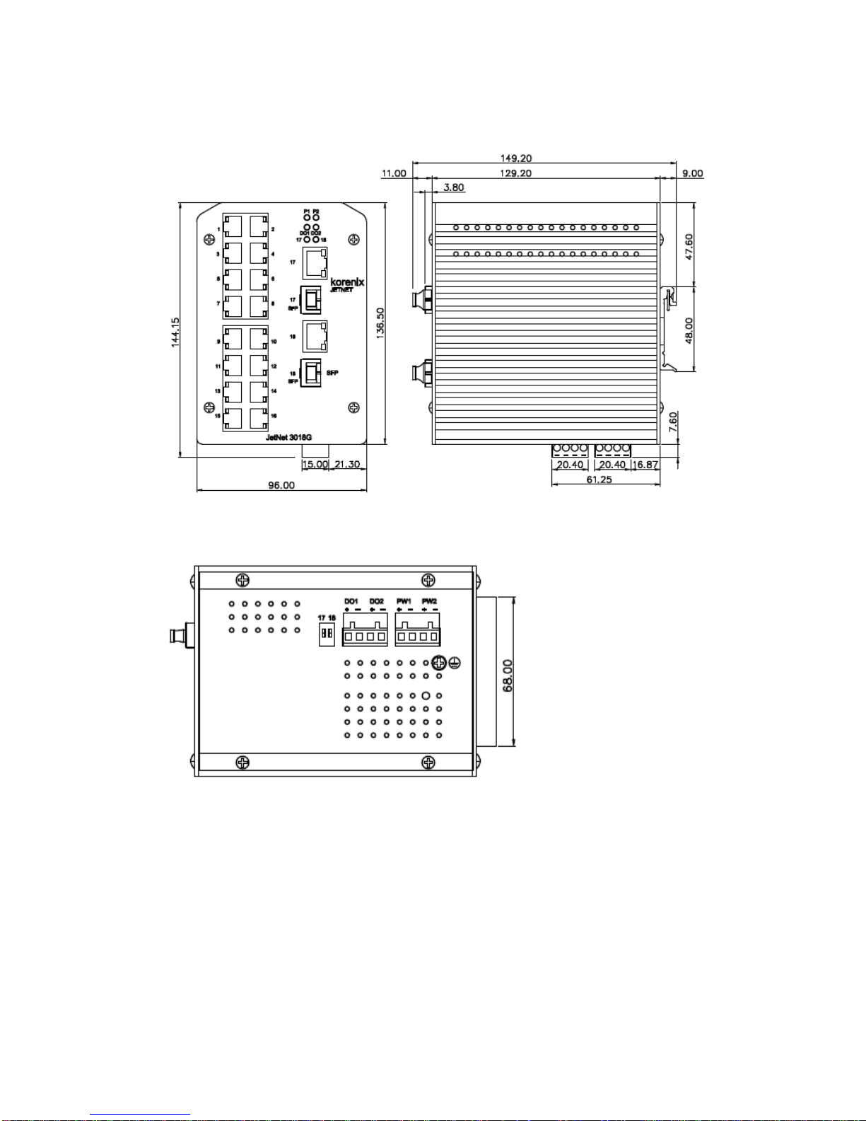
5
Figure of the JetNet 3018G
Bottom view of the JetNet 3018G
6
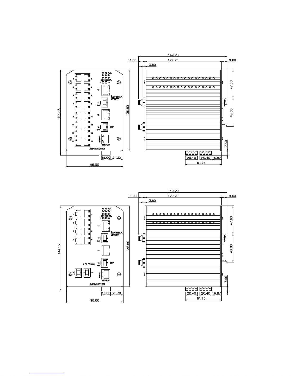
Figure of the JetNet 4518/5018G/5018G v2.0
Figure of the JetNet 5012G
The Bottom dimension is the same as the JetNet 3018G.
Besides the DIP switch on JetNet 3018G, the other placement of JetNet 4518, 5018G
and 5012G is the same as JetNet 3018G.
7
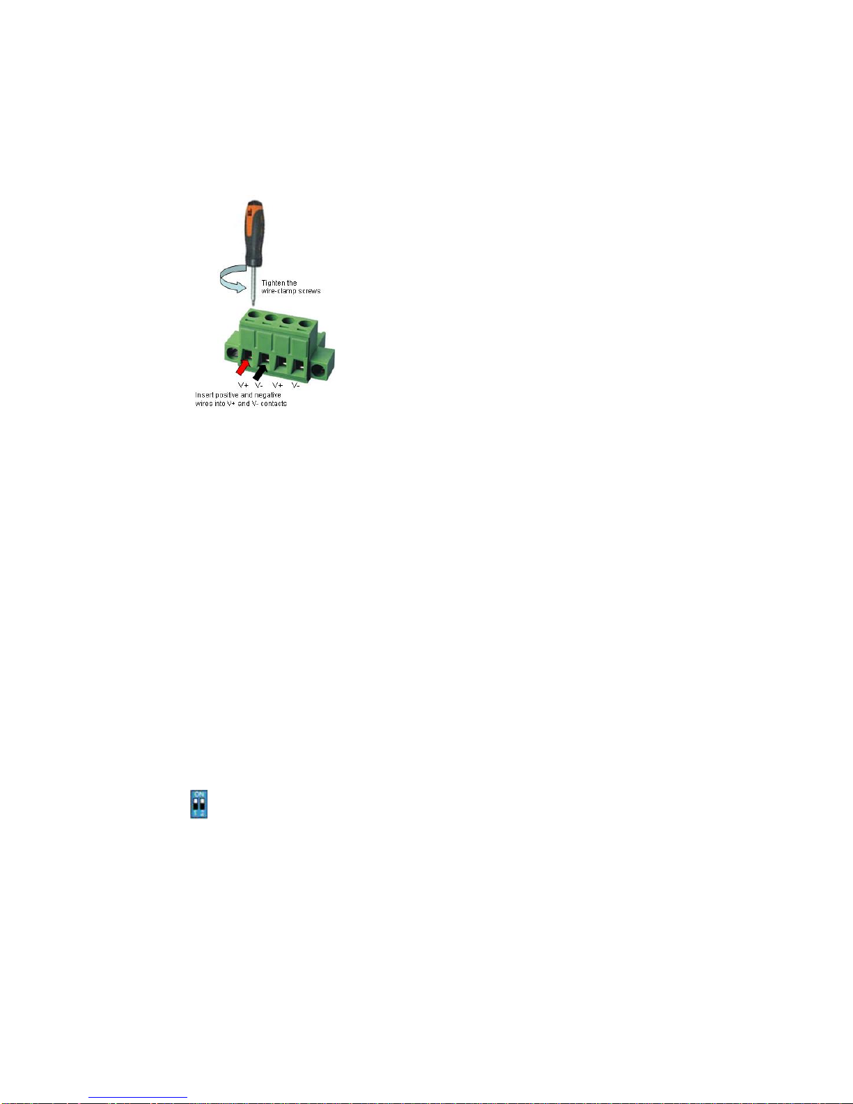
2.2 Wiring Power Inputs
DC Power Input
Follow below steps to wire redundant DC power inputs.
1. Insert positive and negative wires into V+ and Vcontacts respectively of the terminal block
connector
2. Tighten the wire-clamp screws to prevent DC
wires from being loosened.
3. Power 1 and Power 2 support power redundancy
and polarity reverse protection functions.
4. Positive and negative power system inputs are
both accepted, but Power 1 and Power 2 must
apply the same mode.
Note 1: It is a good practice to turn off input and load power, and to unplug power terminal
block before making wire connections. Otherwise, your screwdriver blade can
inadvertently short your terminal connections to the grounded enclosure.
Note 2: The range of the suitable DC electric wire is from 12 to 24 AWG.
Note 3: If the 2 power inputs are connected, the switch will be powered from the highest
connected voltage. The unit will alarm for loss of power, either PWR1 or PWR2.
2.3 Wiring Digital Output
JetNet 3018G/4518/5012G/5018G provide 2 digital outputs, also known as Relay Output.
JetNet 4518/5012G/5018G/5018G v2.0.0:
In JetNet 4518/5012G/5018G, the relay contacts are energized (open) for normal
operation and will close for fault conditions. The fault conditions include power failure,
Ethernet port link break or other pre-defined events which can be configured in
management UI.
JetNet 3018G:
In JetNet 3018G, the Digital Output indicates gigabit port 17 and 18 link down or failure.
Click the equipped DIP 1 to ON to enable the port 17 link failure DO alarm, click the
DIP 2 to ON to enable the port 18 link failure DO alarm.
The default (without power) state of the Digital Output is normal CLOSE state.
Wiring digital output is exactly the same as wiring power input introduced in chapter 2.2.
2.4 Wiring Earth Ground
To ensure the system will not be damaged by noise or any electrical shock, we suggest
you to make exact connection with switch with Earth Ground.
For DC input, loosen the earth ground screw by screw drive; then tighten the screw after
earth ground wire is connected.
8
2.5 Wiring Fast Ethernet Ports
The fast Ethernet ports support 10Base-T and 100Base-TX, full or half duplex modes. All
the fast Ethernet ports will auto-detect the signal from connected devices to negotiate the
link speed and duplex mode. Auto MDI/MDIX allows users to connect another switch, hub
or workstation without changing straight through or crossover cables.
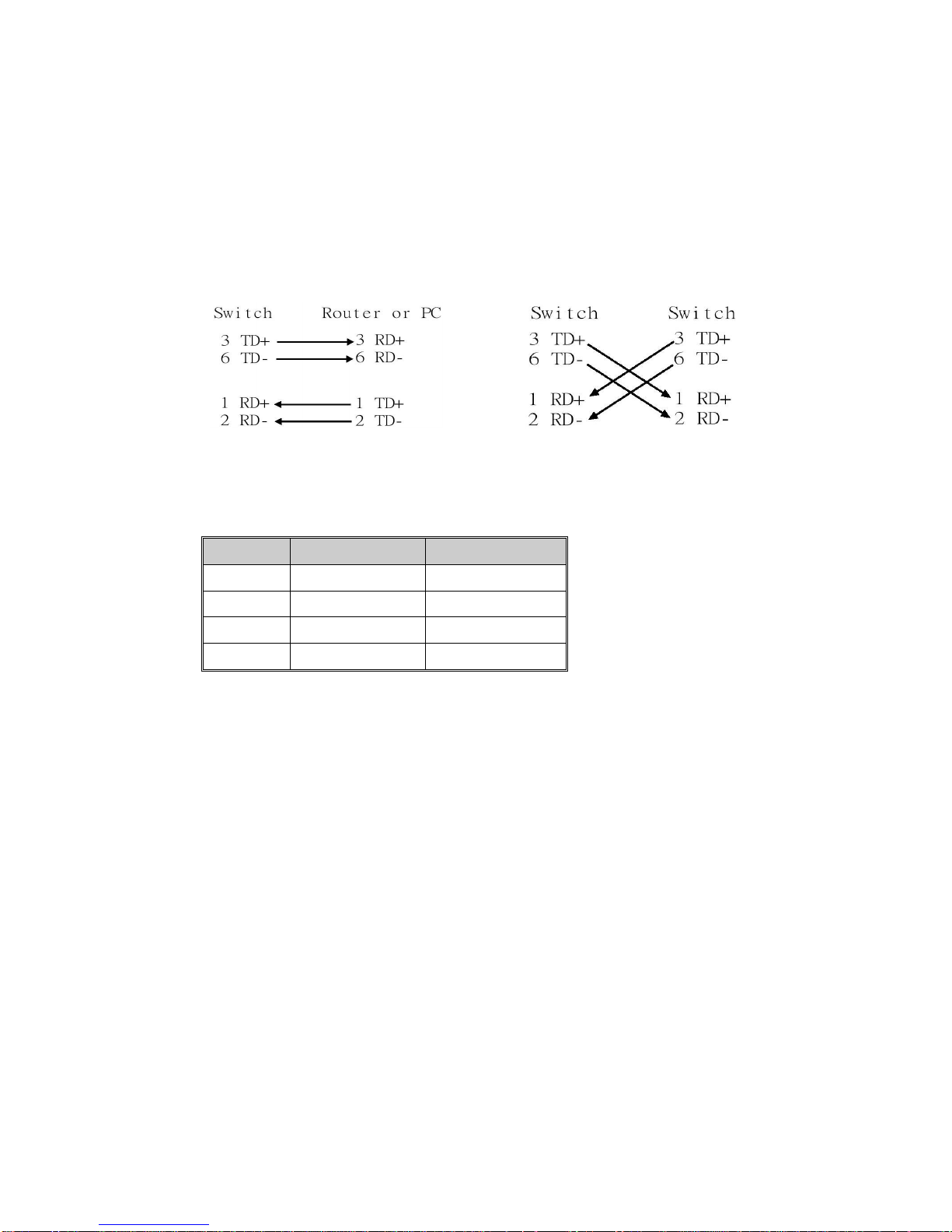
Note that crossover cables simply cross-connect the transmit lines at each end to the
received lines at the opposite end.
Straight-through Cabling Schematic
Cross-over Cabling Schematic
Note that Ethernet cables use pins 1, 2, 3, and 6 of an 8-pin RJ-45 connector. The signals
of these pins are converted by the automatic MDI-X function, as shown in the table below:
Pin MDI-X
Signals
MDI Signals
1
RD+
TD+
2
RD-
TD-
3
TD+
RD+
6
TD-
RD-
Connect one side of an Ethernet cable into any switch port and connect the other side to
your attached device. The LNK LED will light up when the cable is correctly connected.
Refer to the LED Indicators section for descriptions of each LED indicator. Always make
sure that the cables between the switches and attached devices (e.g. switch, hub, or
workstation) are less than 100 meters (328 feet).
The wiring cable types are as below.
10Base-T: 2-pair UTP/STP Cat. 3, 4, 5 cable, EIA/TIA-568 100-ohm (100m)
100 Base-TX: 2-pair UTP/STP Cat. 5 cable, EIA/TIA-568 100-ohm (100m)
1000 Base-TX: 4-pair UTP/STP Cat. 5 cable, EIA/TIA-568 100-ohm (100m)
2.6 Wiring Fiber Ports
Small Form-factor Pluggable (SFP)
The SFP ports accept standard MINI GBIC SFP transceiver. But, to ensure system
reliability, Korenix recommends using the Korenix certificated SFP Transceiver. The
web UI will show Unknown vendor type when choosing the SFP which is not certificated
by Korenix.
The JetNet 3018G/5012G/5018G support Gigabit SFP transceiver, JetNet 4518 supports
100M SFP transceiver, the JetNet 5018G v2.0 supports both 100M and 1000M SFP. The
types of the SFP transceivers include single-/multi-mode fiber, the support range is from
550m to 120KM depends on the capability of the plugged transceiver.
Different type SFP transceiver can work together within the same device. Choose the
types and distance you need. This is the flexibility of the SFP Fiber transceiver.
9
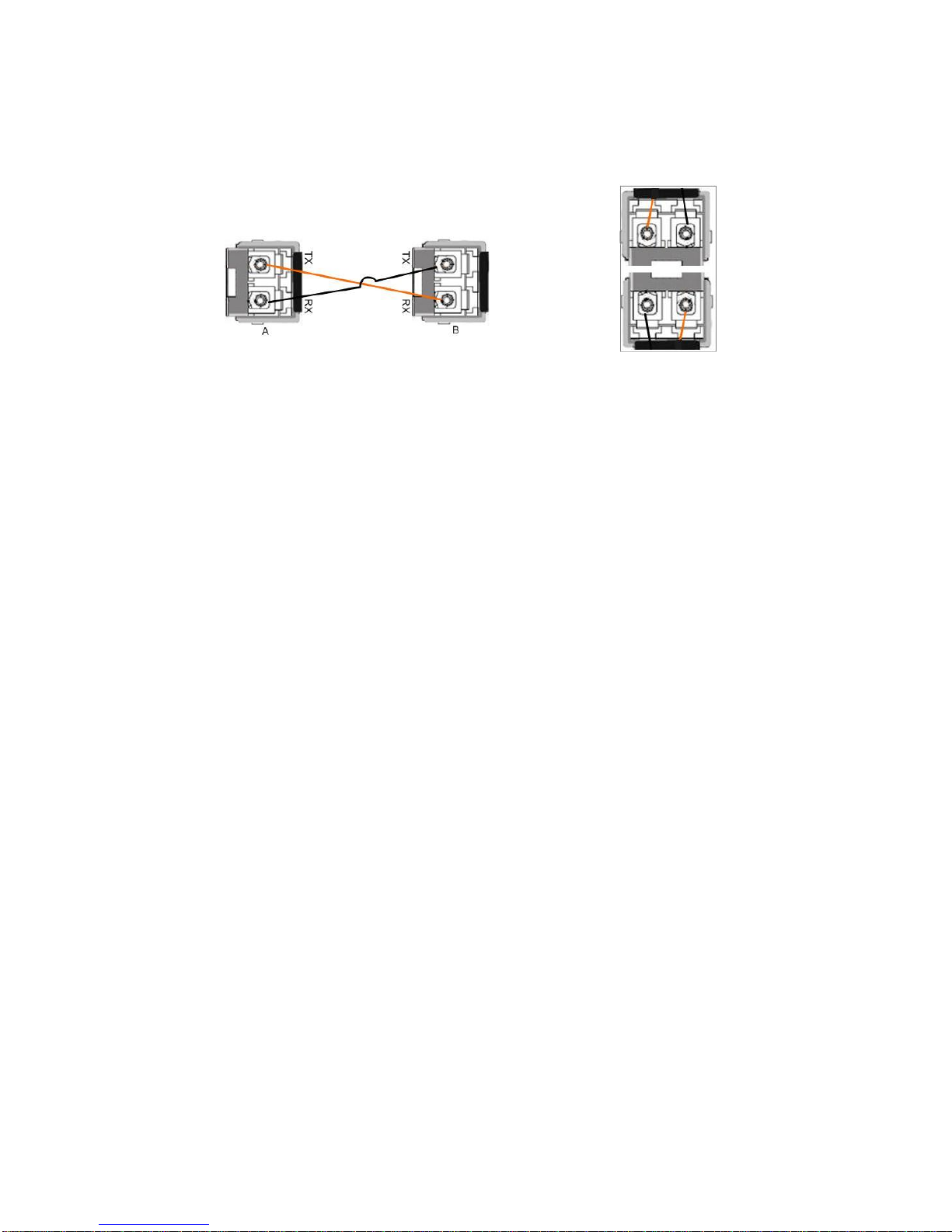
The way to connect the SFP transceiver is to Plug in SFP fiber transceiver fist. Cross-connect the
transmit channel at each end to the receive channel at the opposite end as illustrated in the figure
below. The SPF cage of JetNet 5012G 2G SFP is 2x1 design, check the direction/angle of the fiber
transceiver and fiber cable when inserted.
Note: This is a Class 1 Laser/LED product. Don’t stare at the Laser/LED Beam.
2.7 Wiring Combo Ports
There is Combo Ports design in JetNet managed switch series. The combo port means
the physical interface supports both copper and fiber types, but there is only one of the
types, Copper or Fiber can be used in one time.
JetNet 3018G/5012G/5018G/5018G v2.0
The JetNet 3018G/5012G/5018G/5018G v2.0 include 2 Gigabit RJ-45/SFP Combo
ports. The port number of the JetNet 3018G/5018G/5018G v2.0 is port 17 and 18. The
port number of the JetNet 5012G is port 11 and 12.
The speed of the gigabit Ethernet copper port supports 10Base-TX, 100Base-TX and
1000Base-T. The speed of the SFP Fiber port supports 1000M Full Duplex. The available
gigabit SFP supports Gigabit Single-mode, Multi-mode, BIDI/WDM single-mode SFP
transceivers. (The 100Base-FX is not supported in JetNet 3018G/5012G/5018G Gigabit
combo ports.)
The default value when both types are connected is the active SFP port works first, only
the Fiber link is available when SFP plugged and link up.
JetNet 4518
The JetNet 4518 includes 2 100M RJ-45/SFP combo ports. The speed of the Fast
Ethernet port supports 10Base-TX, 100Base-TX. The speed of the JetNet 4518/5018G
v2.0 SFP port supports 100M Full Duplex. The JetNet 4518 only accept 100Mbps SFP
Transceiver.
The default value when both types are connected is the plugged SFP port works first.
After plugged SFP transceiver, even it is not connected and link up, only the Fiber link is
available. This is the current design and this is not the same as JetNet3018G/ 5012G/
5018G/ 5018G v2.0.
When the SFP transceiver is plugged into SFP lot, the combo mode is changed to Fiber
mode directly. Korenix suggest not connecting Copper and Fiber at the same time.
2.8 Wiring RS-232 Console Cable
Korenix JetNet 4518/ 5012G/ 5018G/ 5018G v2.0 attached one RS-232 DB-9 to RJ-45
cable in the unit box. Connect the RJ-45 connector to the COM port of your PC, open
Terminal tool and set up serial settings to 9600, N,8,1. (Baud Rate: 9600 / Parity: None /
Data Bit: 8 / Stop Bit: 1) Then you can access CLI interface by console able.
Note: If you lost the cable, please contact with your sales or follow the pin assignment to
10
buy a new one. The Pin assignment spec is listed in the appendix.
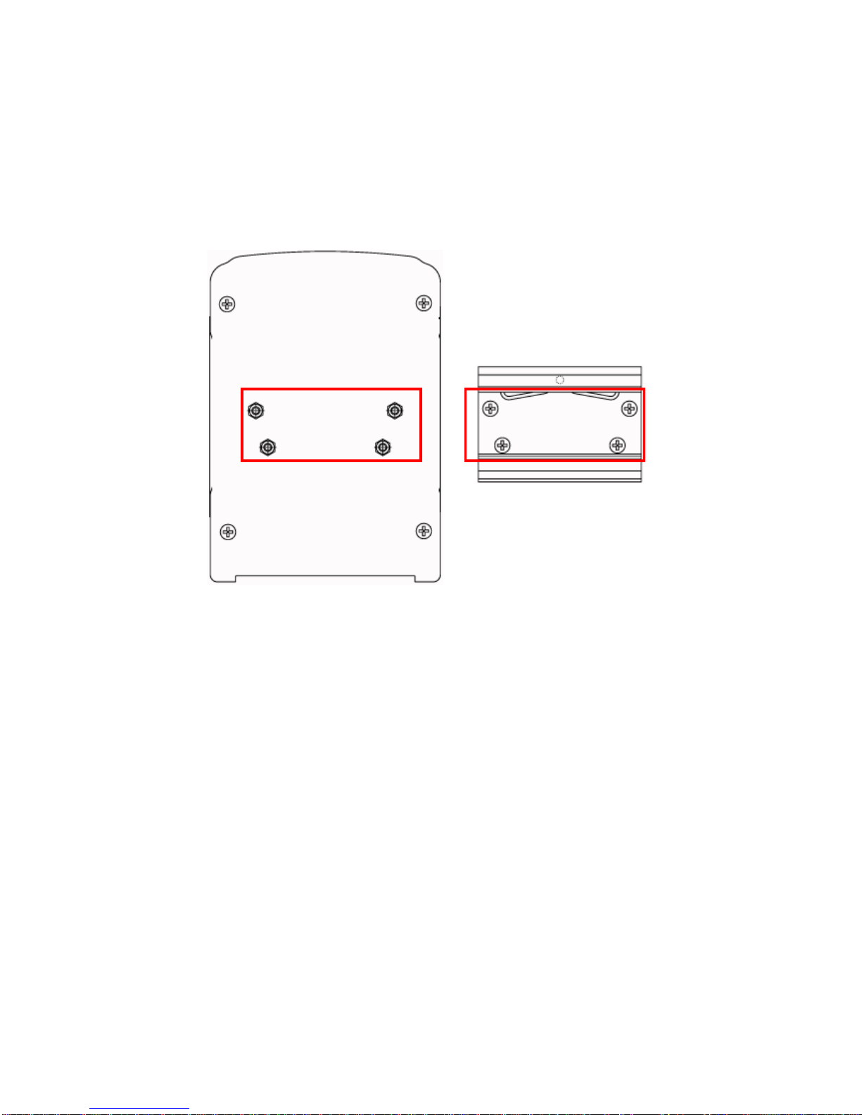
2.9 DIN-Rail Mounting Installation
The DIN-Rail clip is already attached to the JetNet Switch when packaged. If the
DIN-Rail clip is not screwed on the JetNet Switch, follow the instructions and the figure
below to attach DIN-Rail clip to JetNet Switch.
Follow the steps below to mount JetNet Switch to the DIN-Rail track:
1. First, insert the upper end of DIN-Rail clip into the back of DIN-Rail track from its
upper side.
1. Use the screws to attach DIN-Rail clip to the real panel of JetNet
Din Rail Switch.
11
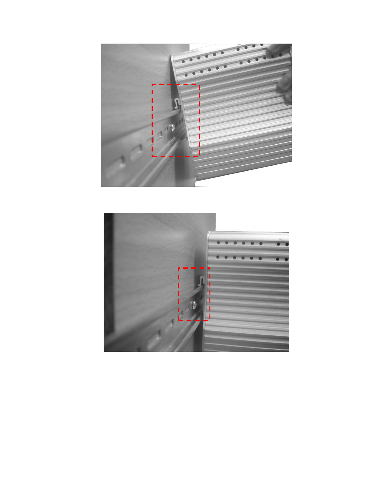
2. Lightly push the bottom of DIN-Rail clip into the track.
3. Check if DIN-Rail clip is tightly attached on the track.
4. To remove JetNet Switch from the track, reverse the steps above.
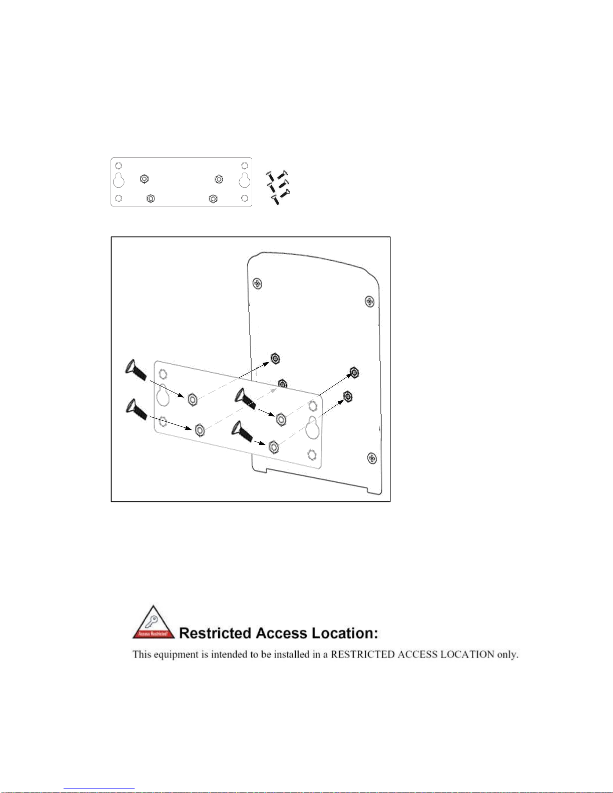
2.10 Wall Mounting Installation
Follow the steps below to install JetNet Switch with the wall mounting plate.
1. To remove DIN-Rail clip from JetNet Switch, loosen the screws from DIN-Rail clip.
12
2. Place the wall mounting plate on the rear panel of JetNet Switch.
3. Use the screws to tighten the wall mounting plate onto JetNet Switch.
4. Use the hook holes at the corners of the wall mounting plate to hang JetNet Switch
onto the wall.
5. To remove the wall mounting plate, reverse the steps above.
Wall-Mounting plate and screws.
2.11 Safety Warming
2.2.1 The Equipment intended for installation in a Restricted Access
Location.
2.2.2 The warning test is provided in user manual. Below is the information:
”For tilslutning af de ovrige ledere, se medfolgende installationsvejledning”.

13
“Laite on liitettava suojamaadoitus-koskettimilla varustettuun pistorasiaan”
„Apparatet ma tilkoples jordet stikkontakt“
”Apparaten skall anslutas till jordat uttag”

14
3 Preparation for Management
JetNet Industrial Managed Switch provides both in-band and out-band configuration
methods. You can configure the switch via RS232 console cable if you don’t attach your
admin PC to your network, or if you lose network connection to your JetNet managed
switch. This is so-called out-band management. It wouldn’t be affected by network
performance.
The in-band management means you can remotely manage the switch via the network.
You can choose Telnet or Web-based management. You just need to know the device’s
IP address and you can remotely connect to its embedded HTTP web pages or Telnet
console.
Should you forget the IP address, you can use JetView Utility to discover the device,
check its IP address or assign new IP address. The JetView Utility can discover the
device across the subnet. Please download the newest version of JetView from
Korenix’s web site.
Following topics are covered in this chapter:
3.1 Preparation for Serial Console
3.2 Preparation for Web Interface
3.3 Preparation for Telnet console
3.1 Preparation for Serial Console
In JetNet Managed Switch package, Korenix attached one RS-232 DB-9 to DB-9/RJ-45
console cable. Please attach RS-232 DB-9 connector to your PC COM port, connect the
other end to the Console port of the JetNet Managed Switch. If you lose the cable,
please follow the console cable PIN assignment to find one. (Refer to the appendix).
1. Go to Start -> Program -> Accessories -> Communication -> Hyper Terminal
2. Give a name to the new console connection.
3. Choose the COM name
4. Select correct serial settings. The serial settings of JetNet Managed Switch are as
below:
Baud Rate: 9600 / Parity: None / Data Bit: 8 / Stop Bit: 1
5. After connected, you can see Switch login request.
6. Login the switch. The default username is “admin”, password, “admin”.
Booting...
Sun Jan 1 00:00:00 UTC 2006
Switch login: admin
Password:
JetNet5018G (version 0.2.25-20090414-11:04:13).
Copyright 2006-2009 Korenix Technology Co., Ltd.
Switch>
15
3.2 Preparation for Web Interface
JetNet Managed Switch provides HTTP Web Interface and Secured HTTPS Web
Interface for web management.
3.2.1 Web Interface
Korenix web management page is developed by JAVA. It allows you to use a standard
web-browser such as Microsoft Internet Explorer, or Mozila, to configure and interrogate
the switch from anywhere on the network.
Before you attempt to use the embedded web interface to manage switch operation,
verify that your JetNet Industrial Managed Ethernet Switch is properly installed on your
network and that every PC on this network can access the switch via the web browser.
1. Verify that your network interface card (NIC) is operational, and that your operating
system supports TCP/IP protocol.
2. Wire DC power to the switch and connect your switch to your computer.
3. Make sure that the switch default IP address is 192.168.10.1.
4. Change your computer IP address to 192.168.10.2 or other IP address which is
located in the 192.168.10.x (Network Mask: 255.255.255.0) subnet.
5. Switch to DOS command mode and ping 192.168.10.1 to verify a normal response
time.
Launch the web browser and Login.
6. Launch the web browser (Internet Explorer or Mozila Firefox) on the PC.
7. Type http://192.168.10.1 (or the IP address of the switch). And then press Enter.
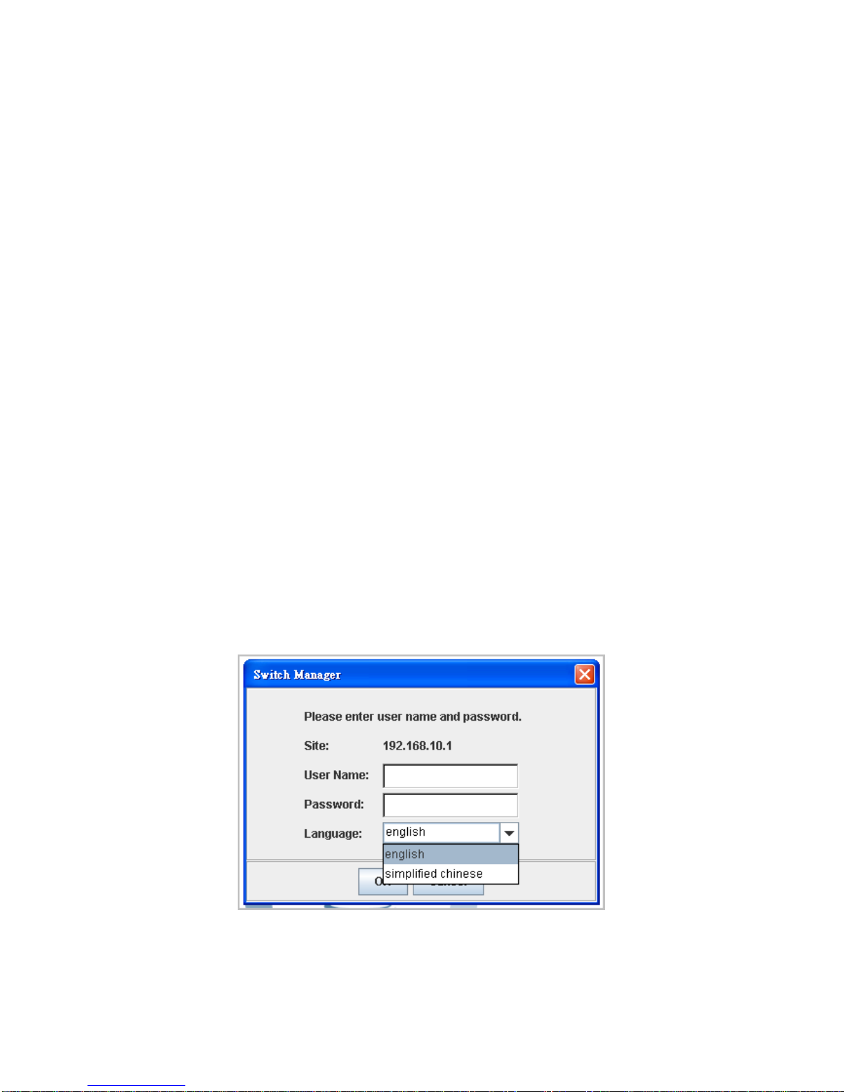
8. The login screen will appear next.
9. Key in user name and the password. Default user name and password are both
admin.
10. Select Language type, this feature is available from firmware v1.3, and supports
English and Simplified Chinese user interface.
Click on Enter or OK. Welcome page of the web-based management interface will then
appear.
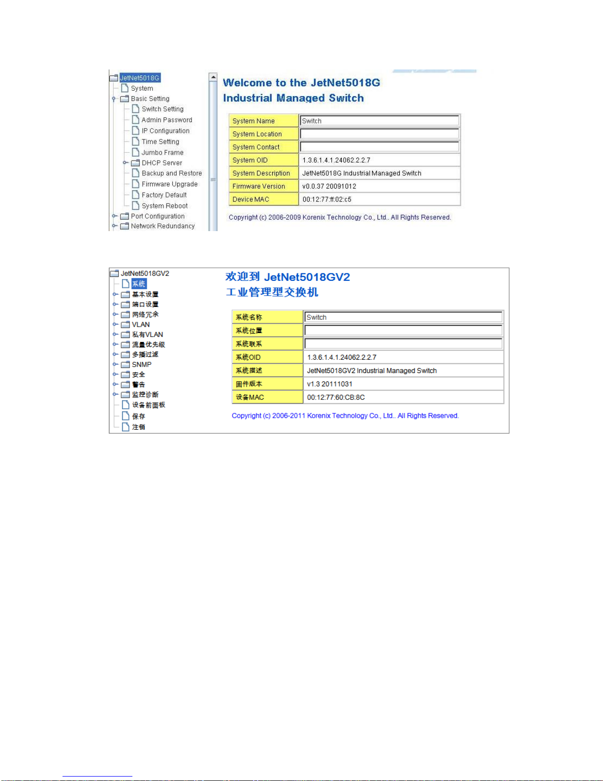
16
Once you enter the web-based management interface, you can freely change the
JetNet’s IP address to fit your network environment.
Note 1: IE 5.0 or later versions do not allow Java applets to open sockets by default.
Users have to directly modify the browser settings to selectively enable Java applets to
use network ports.
Note 2: The Web UI connection session of JetNet Managed Switch will be logged out
automatically if you don’t give any input after 30 seconds. After logged out, you should
re-login and key in correct user name and password again.
3.2.2 Secured Web Interface
Korenix web management page also provides secured management HTTPS login. All
the configuration commands will be secured and will be hard for the hackers to sniff the
login password and configuration commands.
Launch the web browser and Login.
1. Launch the web browser (Internet Explorer or Mozila Firefox) on the PC.
2. Type https://192.168.10.1 (or the IP address of the switch). And then press Enter.
English interface
中文介面
17
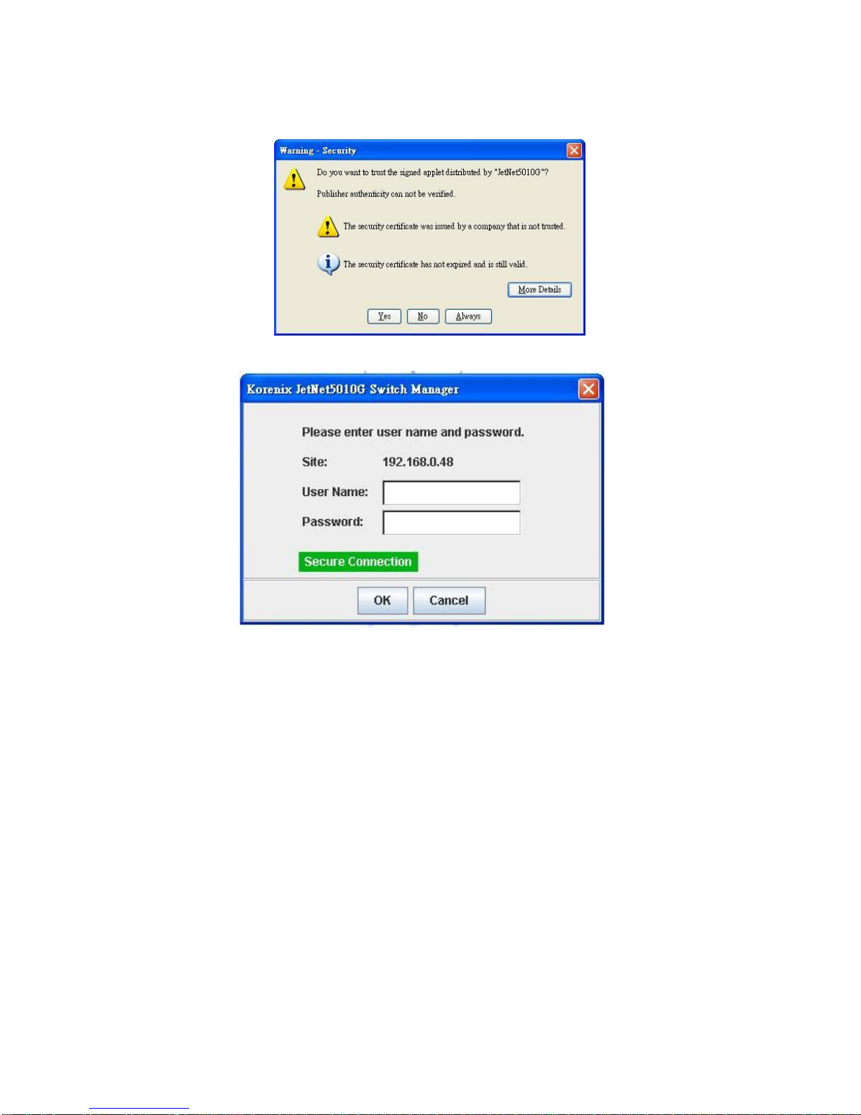
3. The popup screen will appear and request you to trust the secured HTTPS
connection distributed by JetNet Managed Switch first. Press Yes to trust it.
4. The login screen will appear next.
5. Key in the user name and the password. The default user name and password is
admin.
6. Click on Enter or OK. Welcome page of the web-based management interface will
then appear.
7. Once you enter the web-based management interface, all the commands you see
are the same as what you see by HTTP login.
3.3 Preparation for Telnet Console
3.3.1 Telnet
Korenix JetNet managed Switch supports Telnet console. You can connect to the switch
by Telnet and the command lines are the same as what you see by RS232 console port.
Below are the steps to open Telnet connection to the switch.
1. Go to Start -> Run -> cmd. And then press Enter
2. Type the Telnet 192.168.10.1 (or the IP address of the switch). And then press
Enter
18
3.3.2 SSH (Secure Shell)
Korenix JetNet Managed Switch also support SSH console. You can remotely connect
to the switch by command line interface. The SSH connection can secure all the
configuration commands you sent to the switch.
SSH is a client/server architecture while JetNet Managed Switch is the SSH server.
When you want to make SSH connection with the switch, you should download the SSH
client tool first.
SSH Client
There are many free, sharewares, trials or charged SSH clients you can find on the
internet. Fox example, PuTTY is a free and popular Telnet/SSH client. We’ll use this
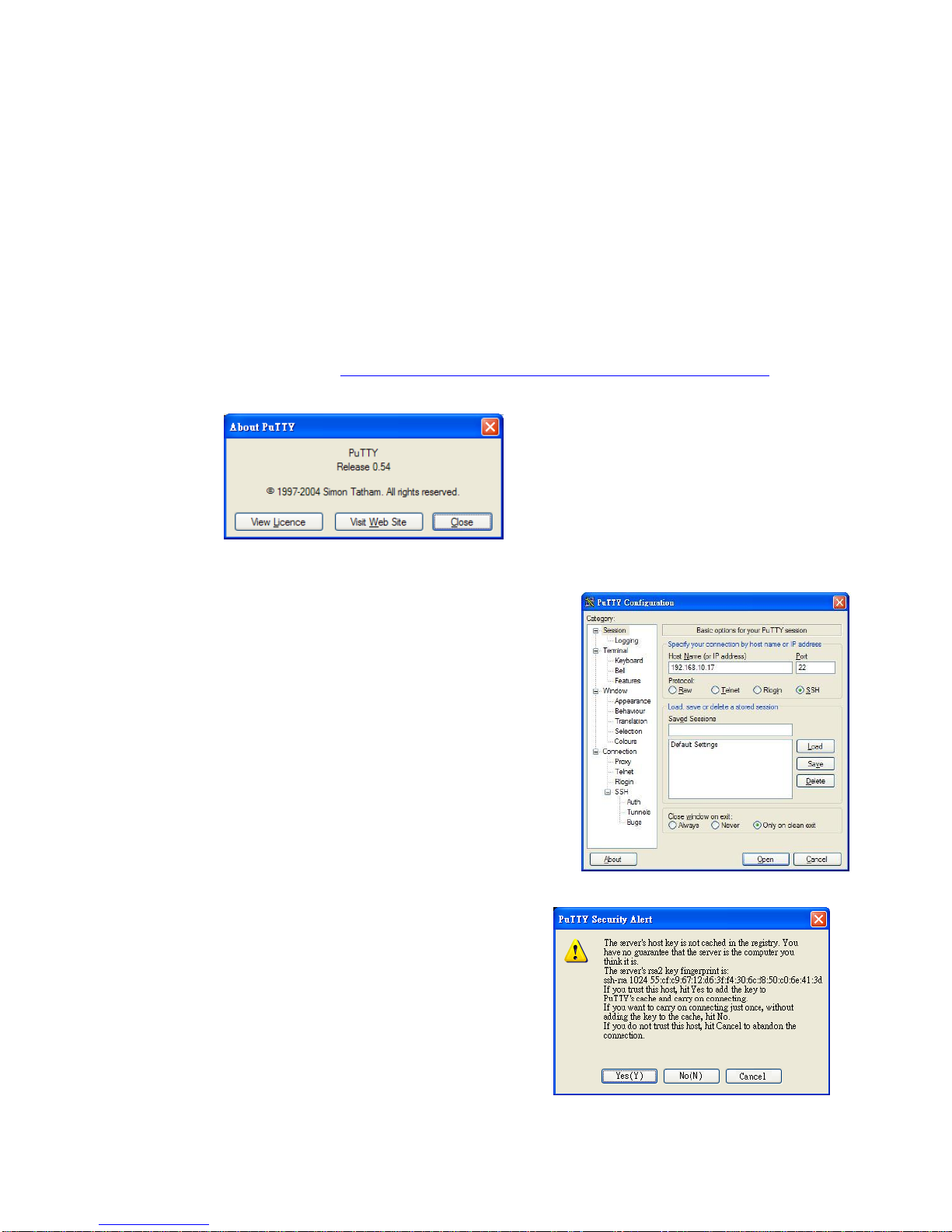
tool to demonstrate how to login JetNet by SSH. Note: PuTTY is copyright 1997-2006
Simon Tatham.
Download PuTTY: http://www.chiark.greenend.org.uk/~sgtatham/putty/download.html
The copyright of PuTTY
1. Open SSH Client/PuTTY
In the Session configuration, enter the Host Name (IP
Address of your JetNet Managed Switch) and Port
number (default = 22). Choose the “SSH” protocol.
Then click on “Open” to start the SSH session console.
2. After click on Open, then you can see the
cipher information in the popup screen. Press
Yes to accept the Security Alert.
19
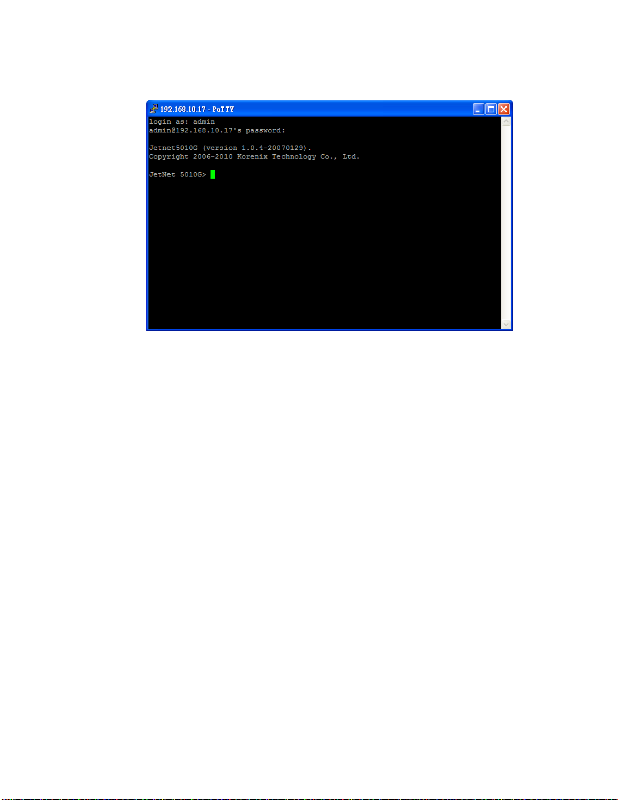
3. After few seconds, the SSH connection to JetNet Managed Switch is opened. You
can see the login screen as the below figure.
4. Type the Login Name and its Password. The default Login Name and Password are
admin / admin.
5. All the commands you see in SSH are the same as the CLI commands you see via
RS232 console. The next chapter will introduce in detail how to use command line to
configure the switch.

20
4 Feature Configuration
This chapter explains how to configure JetNet Managed Switch’s software features. There
are four ways to access the switch: Serial console, Telnet, Web browser and SNMP.
JetNet Industrial Managed Switch Series provides both in-band and out-band configuration
methods. You can configure the switch via RS232 console cable if you don’t attach your
admin PC to your network, or if you lose the network connection to your JetNet Managed
Switch. This is so-called out-band management. It wouldn’t be affected by the network
performance.
The in-band management means you can remotely manage the switch via the network.
You can choose Telnet or Web-based management. You just need to know the device’s IP
address. Then you can remotely connect to its embedded HTML web pages or Telnet
console.
Korenix web management page is developed by JAVA. It allows you to use a standard
web-browser such as Microsoft Internet Explorer, or Mozila, to configure and interrogate
the switch from anywhere on the network.
Note: IE 5.0 or later versions do not allow Java applets to open sockets by default. Users
have to directly modify the browser settings to selectively enable Java applets to use
network ports.
Following topics are covered in this chapter:
4.1 Command Line Interface (CLI) Introduction
4.2 Basic Setting
4.3 Port Configuration
4.4 Network Redundancy
4.5 VLAN
4.6 Traffic Prioritization
4.7 Multicast Filtering
4.8 SNMP
4.9 Security
4.10 Warning
4.11 Monitor and Diag
4.12 Device Front Panel
4.13 Save
4.14 Logout

21
4.1 Command Line Interface Introduction
The Command Line Interface (CLI) is the user interface to the switch’s embedded software
system. You can view the system information, show the status, configure the switch and
receive a response back from the system by keying in a command.
There are some different command modes. Each command mode has its own access
ability, available command lines and uses different command lines to enter and exit. These
modes are User EXEC, Privileged EXEC, Global Configuration, (Port/VLAN) Interface
Configuration modes.
User EXEC mode: As long as you login the switch by CLI. You are in the User EXEC mode.
You can ping, telnet remote device, and show some basic information.
Type enable to enter next mode, exit to logout. ? to see the command list
Privileged EXEC mode: Press enable in the User EXEC mode, then you can enter the
Privileged EXEC mode. In this mode, the system allows you to view current configuration,
reset default, reload switch, show system information, save configuration…and enter the
global configuration mode.
Type configure terminal to enter next mode, exit to leave. ? to see the command list
JN5018G>
enable Turn on privileged mode command
exit Exit current mode and down to previous mode
list Print command list
ping Send echo messages
quit Exit current mode and down to previous mode
show Show running system information
telnet Open a telnet connection
traceroute Trace route to destination
Switch#
archive manage archive files
clear Reset functions
clock Configure time-of-day clock
configure Configuration from vty interface
copy Copy from one file to another
debug Debugging functions (see also 'undebug')
disable Turn off privileged mode command
end End current mode and change to enable mode
exit Exit current mode and down to previous mode
list Print command list
more Display the contents of a file
no Negate a command or set its defaults
ping Send echo messages
quit Exit current mode and down to previous mode
reboot Reboot system
reload copy a default-config file to replace the current one
show Show running system information
telnet Open a telnet connection
terminal Set terminal line parameters
traceroute Trace route to destination
write Write running configuration to memory, network, or terminal

22
Global Configuration Mode: Press configure terminal in privileged EXEC mode. You
can then enter global configuration mode. In global configuration mode, you can configure
all the features that the system provides you.
Type interface IFNAME/VLAN to enter interface configuration mode, exit to leave. ? to
see the command list.
Available command lists of global configuration mode.
(Port) Interface Configuration: Press interface IFNAME in global configuration mode.
You can then enter interface configuration mode. In this mode, you can configure port
settings.
The port interface name of the fast Ethernet port is fa<Port Number>. Ex: Fast Ethernet
Port 1 fa1, fast Ethernet port 7 is fa7, fast Ethernet port 17 is fa17.
The port interface name of the Gigabit Ethernet port is gi<Port Number>. Ex: Gigabit Port 8
is gi9, Gigabit Port 17 is gi17. Even you apply fixed 100M speed to the gigabit port, the port
intergace name is still gi<Port Number>.
Types interface name accordingly when you want to enter certain interface configuration
mode.
Switch# configure terminal
Switch(config)#
access-list Add an access list entry
administrator Administrator account setting
arp Set a static ARP entry
clock Configure time-of-day clock
default Set a command to its defaults
end End current mode and change to enable mode
exit Exit current mode and down to previous mode
gvrp GARP VLAN Registration Protocol
hostname Set system's network name
interface Select an interface to configure
ip IP information
lacp Link Aggregation Control Protocol
list Print command list
log Logging control
mac Global MAC configuration subcommands
mac-address-table mac address table
mirror Port mirroring
no Negate a command or set its defaults
ntp Configure NTP
password Assign the terminal connection password
qos Quality of Service (QoS)
relay relay output type information
smtp-server SMTP server configuration
snmp-server SNMP server
spanning-tree spanning tree algorithm
super-ring super-ring protocol
trunk Trunk group configuration
vlan Virtual LAN
warning-event Warning event selection
write-config Specify config files to write to

23
Type exit to leave.
Type ? to see the command list
Available command lists of the (port) Interface configuration mode.
(VLAN) Interface Configuration: Press interface VLAN VLAN-ID in global configuration
mode. You can then enter VLAN interface configuration mode. In this mode, you can
configure the settings for the specific VLAN.
The VLAN interface name of VLAN 1 is VLAN 1, VLAN 2 is VLAN 2…
Type exit to leave the mode. Type ? to see the available command list.
The command lists of the VLAN interface configuration mode.
Switch(config)# interface vlan 1
Switch(config-if)#
description Interface specific description
end End current mode and change to enable mode
exit Exit current mode and down to previous mode
ip Interface Internet Protocol config commands
list Print command list
no Negate a command or set its defaults
quit Exit current mode and down to previous mode
shutdown Shutdown the selected interface
Switch(config)# interface fa1
Switch(config-if)#
acceptable Configure 802.1Q acceptable frame types of a port.
auto-negotiation Enable auto-negotiation state of a given port
description Interface specific description
duplex Specify duplex mode of operation for a port
end End current mode and change to enable mode
exit Exit current mode and down to previous mode
flowcontrol Set flow-control value for an interface
garp General Attribute Registration Protocol
ingress 802.1Q ingress filtering features
lacp Link Aggregation Control Protocol
list Print command list
loopback Specify loopback mode of operation for a port
mac MAC interface commands
mdix Enable mdix state of a given port
no Negate a command or set its defaults
qos Quality of Service (QoS)
quit Exit current mode and down to previous mode
rate-limit Rate limit configuration
shutdown Shutdown the selected interface
spanning-tree spanning-tree protocol
speed Specify the speed of a Fast Ethernet port or a Gigabit
Ethernet port.
switchport Set switching mode characteristics

24
Summary of the 5 command modes.
Command
Mode
Main Function
Enter and Exit Method
Prompt
User EXEC
This is the first level of access.
User can ping, telnet remote
device, and show some basic
information
Enter: Login successfully
Exit: exit to logout.
Next mode: Type enable to
enter privileged EXEC mode.
Switch>
Privileged
EXEC
In this mode, the system allows
you to view current configuration,
reset default, reload switch, show
system information, save
configuration…and enter global
configuration mode.
Enter: Type enable in User
EXEC mode.
Exec: Type disable to exit to
user EXEC mode.
Type exit to logout
Next Mode: Type configure
terminal to enter global
configuration command.
Switch#
Global
configuration
In global configuration mode, you
can configure all the features that
the system provides you
Enter: Type configure
terminal in privileged EXEC
mode
Exit: Type exit or end or press
Ctrl-Z to exit.
Next mode: Type interface
IFNAME/ VLAN VID to enter
interface configuration mode
Switch(config)#
Port
Interface
configuration
In this mode, you can configure
port related settings.
Enter: Type interface IFNAME
in global configuration mode.
Exit: Type exit or Ctrl+Z to
global configuration mode.
Type end to privileged EXEC
mode.
Switch(config-if)#
VLAN Interface
Configuration
In this mode, you can configure
settings for specific VLAN.
Enter: Type interface VLAN
VID in global configuration
mode.
Exit: Type exit or Ctrl+Z to
global configuration mode.
Type end to privileged EXEC
mode.
Switch(config-vlan)#
25
Here are some useful commands for you to see these available commands. Save your
time in typing and avoid typing error.
? To see all the available commands in this mode. It helps you to see the next command
you can/should type as well.
(Character)? To see all the available commands starts from this character.
Tab This tab key helps you to input the command quicker. If there is only one available
command in the next, clicking on tab key can help to finish typing soon.
Ctrl+C To stop executing the unfinished command.
Ctrl+S To lock the screen of the terminal. You can’t input any command.
Ctrl+Q To unlock the screen which is locked by Ctrl+S.
Ctrl+Z To exit configuration mode.
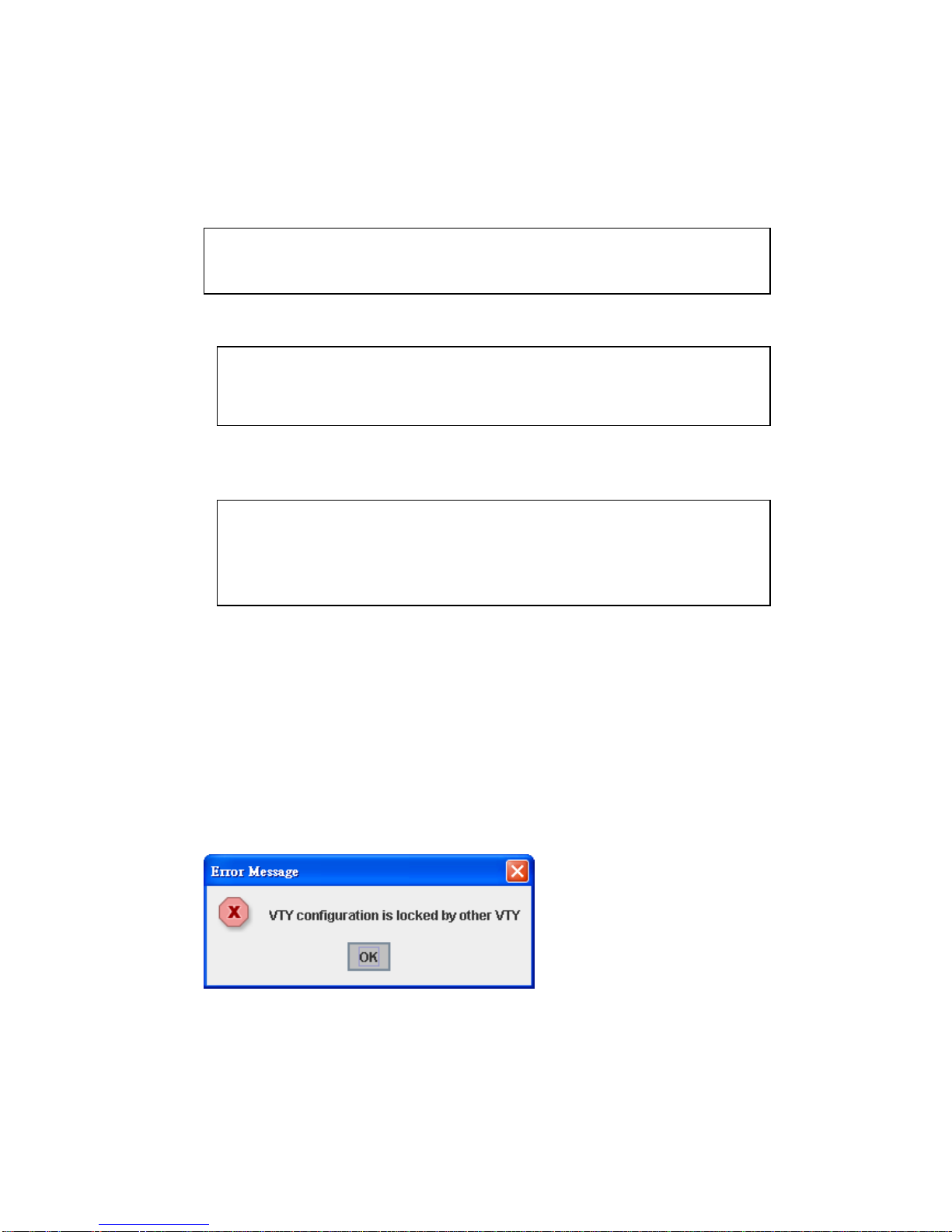
Alert message when multiple users want to configure the switch. If the administrator is in
configuration mode, then the Web users can’t change the settings. JetNet Managed
Switch allows only one administrator to configure the switch at a time.
Switch(config)# a?
access-list Add an access list entry
administrator Administrator account setting
arp Set a static ARP entry
Switch# co (tab) (tab)
Switch# configure terminal
Switch(config)# ac (tab)
Switch(config)# access-list
Switch(config)# interface (?)
IFNAME Interface's name
vlan Select a vlan to configure
26
4.2 Basic Setting
The Basic Setting group provides you to configure switch information, IP address, User
name/Password of the system. It also allows you to do firmware upgrade, backup and
restore configuration, reload factory default, and reboot the system.
Following commands are included in this group:
4.2.1 Switch Setting
4.2.2 Admin Password
4.2.3 IP Configuration
4.2.4 Time Setting
4.2.5 Jumbo Frame
4.2.6 DHCP Server
4.2.7 Backup and Restore
4.2.8 Firmware Upgrade
4.2.9 Factory Default
4.2.10 System Reboot
4.2.11 CLI Commands for Basic Setting
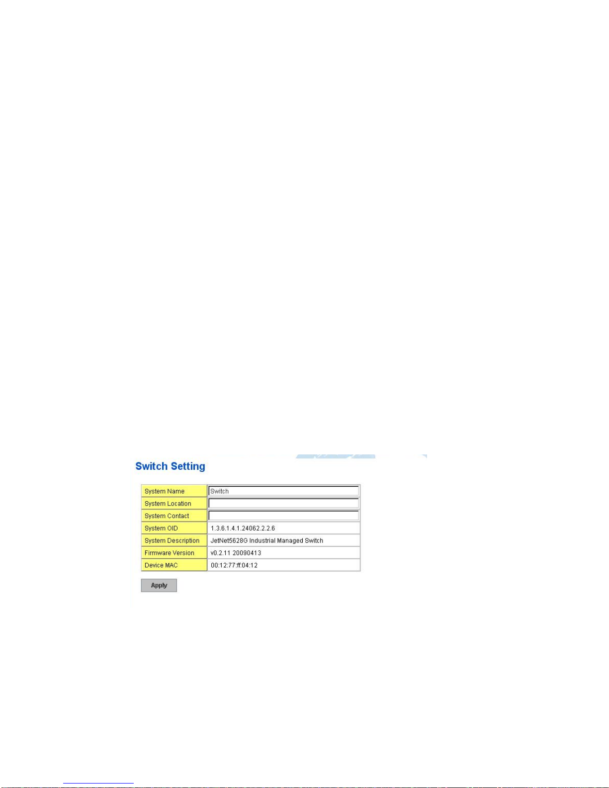
4.2.1 Switch Setting
You can assign System name, Location, Contact and view system information.
Figure 4.2.1.1 – Web UI of the Switch Setting
System Name: You can assign a name to the device. The available characters you can
input is 64. After you configure the name, CLI system will select the first 12 characters as
the name in CLI system.
System Location: You can specify the switch’s physical location here. The available
characters you can input are 64.
System Contact: You can specify contact people here. You can type the name, mail
address or other information of the administrator. The available characters you can input
are 64.
 Loading...