

Korenix JetNet 4508 V2 Series, JetNet 4508f V2 Series User Manual

1
JetNet 4508 V2 /4508f V2 Series
Industrial 8-port Managed Fast Ethernet Switch
User’s Manual
Version 0.3
Firmware V0.1.41
www.korenix.com

2
JetNet 4508 V2 / 4508f V2 Series
Industrial 8-port Managed Fast Ethernet Switch
User’s Manual
Copyright Notice
Copyright © 2010 Korenix Technology Co., Ltd.
All rights reserved.
Reproduction in any form or by any means without permission is prohibited.

3
Declaration of CE
This product has passed the CE certification for environmental
specifications. Test conditions for passing included the equipment being
operated within an industrial enclosure. In order to protect the product
from being damaged by ESD (Electrostatic Discharge) and EMI leakage,
we strongly recommend the use of CE-compliant industrial enclosure
products.
Federal Communications Commission (FCC) Statement
This equipment has been tested and found to comply with the limits for a
Class A digital device, pursuant to Part 15 of the FCC Rules. These limits
are designed to provide reasonable protection against harmful
interference when the equipment is operated in a commercial environment.
This equipment generates, uses, and can radiate radio frequency energy
and, if not installed and used in accordance with the instruction manual,
may cause harmful interference to radio communications. Operation of
this equipment in a residential area is likely to cause harmful interference
in which case the user will be required to correct the interference at his
expense.
The user is cautioned that changes and modifications made to the
equipment without approval of the manufacturer could void the user's
authority to operate this equipment.

Index
1 Introduction.............................................................................................2
1.1 Overview........................................................................................2
1.2 Major Features...............................................................................2
1.3 Package List ..................................................................................3
2 Hardware Installation..............................................................................4
2.1 Hardware Introduction....................................................................5
2.2 Wiring the Power Inputs...............................................................10
2.3 Wiring Digital Input.......................................................................12
2.4 Wiring Digital Output....................................................................12
2.5 Wiring Earth Ground ....................................................................13
2.6 Wiring Fast Ethernet RJ-45 Ports.................................................14
2.7 Wiring Fast Ethernet Fiber port (JetNet 4508f V2).......................15
2.8 Wiring RS-232 Console Cable .....................................................15
2.9 DIN-Rail Mounting Installation......................................................16
3 Preparation for Management ...............................................................17
3.1 Preparation for Serial Console.....................................................18
3.2 Preparation for Web Interface......................................................19
3.3 Preparation for Telnet Console.....................................................22
4 Feature Configuration ..........................................................................25
4.1 Command Line Interface Introduction..........................................26
4.2 Basic Setting................................................................................31
4.3 Port Configuration........................................................................50
4.4 Network Redundancy...................................................................60
4.5 VLAN............................................................................................70
4.6 Traffic Prioritization.......................................................................79
4.7 Multicast Filtering.........................................................................84
4.8 SNMP...........................................................................................89
4.9 Security........................................................................................93
4.10 Warning......................................................................................100
4.11 Monitor and Diag........................................................................110
4.12 Device Front Panel.....................................................................119
4.13 Save to Flash.............................................................................120
4.14 Logout........................................................................................121
5 Appendix .............................................................................................122
5.1 Product Specifications................................................................122
5.2 Korenix Private MIB ...................................................................127

1
5.3 Revision History.........................................................................129
5.4 About Korenix ............................................................................130

2
1 Introduction
Welcome to Korenix JetNet 4508 V2 / 4508f V2 Series Industrial 8-port
Managed Fast Ethernet Switch User Manual. Following topics are
covered in this chapter:
1.1 Overview
1.2 Major Features
1.3 Package Checklist
1.1 Overview
The JetNet 4508 V2/ 4508f V2 series are 8-port industrial managed Fast
Ethernet Switch designed with advanced Layer 2 management features
and high system reliability, including MSR and MSTP network redundancy
technologies, for ensuring real-time and high quality connectivity in various
networking applications. The Ethernet switches includes 8 10/100Mbps
Fast Ethernet ports with RJ-45 connectors (JetNet 4508 V2) or 6
10/100Mbps Fast Ethernet ports plus 2 100Mbps Fast Ethernet Fiber ports.;
Both of switches adopted 32Gbps switch fabric to provide real time
non-blocking transmission performance for satisfying the needs of high
bandwidth data transmission requiring applications while ensuring traffic
switching without data loss. Besides, the new system design includes a
hardware based watchdog timer for keeping the operating system live. It
also provides power redundancy with wide range DC10V~60V inputs for
ensuring the power continuity in the system. Combining the outstanding L2
management features along with the LLDP and the JetView Pro Intelligent
NMS into the ruggedized design with IP31 enclosure and -25~70°C
(regular version) and -40~75°C (-w version) wide operating temperature,
JetNet 4508V2 series provide highly reliable and secure data transmission
under severe industrial environments.
1.2 Major Features
The JetNet Managed Switch has the following features:
8 10/100TX ports with Auto MDI/MDI-X
32Gbps Non-Blocking, 8K MAC address table
Multiple Super Ring (recovery time <5ms), Rapid Dual Homing,
3
Multiple Ring, and MSTP / RSTP
IEEE 1588 Precision Time Protocol for precise time synchronization
VLAN, Private VLAN, QinQ, GVRP, QoS, IGMP Snooping V1/V2/V3,
Rate Control, Port Trunking, LACP, Online Multi-Port Mirroring
IEEE 802.1AB LLDP and JetView Pro i2NMS for auto-topology and
group management
Supports SNMP, Web, Telnet In-Band, Serial Out-Band Management
Embedded Hardware Watchdog for System Auto Rescue
Dual DC10~60V Power Inputs with Redundancy
Software configurable Alarm Output
IP31 rugged aluminum case
Operating temperature:
-25~70°C (JetNet 4508 V2), -10~70°C (JetNet 4508f V2) and
-40~75°C (JetNet 4508-w V2/ JetNet 4508f-w V2)
If there is any specification change, please refere to the Web site or contact
your sales window.
The detail spec is listed in Appendix
Note-1: those certifications are pending for special project request, please
contact your sales widnow.
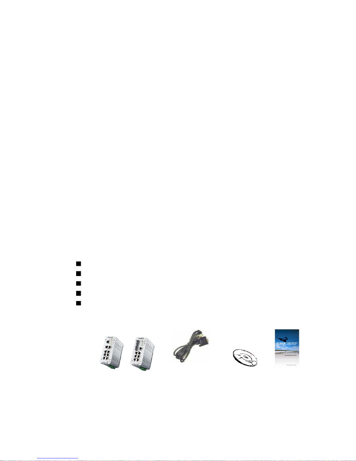
1.3 Package List
Korenix JetNet 4508 V2 Series products are shipped with following items:
JetNet 4508 V2 x1 or JetNet 4508f V2 x1
One DIN-Rail clip (attached to the switch)
One RS-232 DB-9 to RJ-45 console cable
CD User manual x 1
Quick Installation Guide (QIG)
If any of the above items is missing or damaged, please contact your local
sales representative.
DB-9 to RJ-45
Cable
CD User
Manual
QIG
JetNet 4508V2/ JetNet 4508f V2

4
2 Hardware Installation
This chapter includes hardware introduction, installation and
configuration information. Following topics are covered in this chapter:
2.1 Hardware Introduction
Dimension
Panel Layout
Bottom View
2.2 Wiring Power Inputs
2.3 Wiring Digital Input
2.4 Wiring Relay Output
2.5 Wiring Ethernet Ports
2.6 Wiring RS-232 console cable
2.7 DIN-Rail Mounting Installation
5
2.1 Hardware Introduction
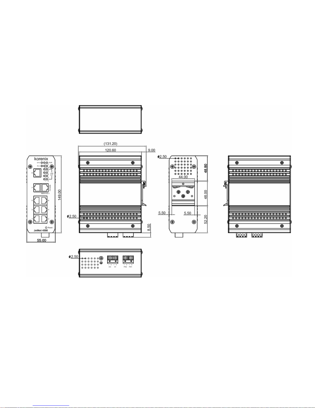
Dimension of JetNet 4508V2
JetNet 4508V2 Industrial 8-port managed Fast Ethernet Switch dimension is:
55 (W) x 149 (H) x 131.2 (D) / with DIN Rail Clip
55 (W) x 149 (H) x 120.6 (D) / without DIN Rail Clip

6
Dimension of JetNet 4508f V2
JetNet 4508f V2 Industrial 6-port plus 2 100Mbps Fiber managed Fast Ethernet
Switch dimension is:
55 (W) x 149 (H) x 131.2 (D) / with DIN Rail Clip
55 (W) x 149 (H) x 120.6 (D) / without DIN Rail Clip
7
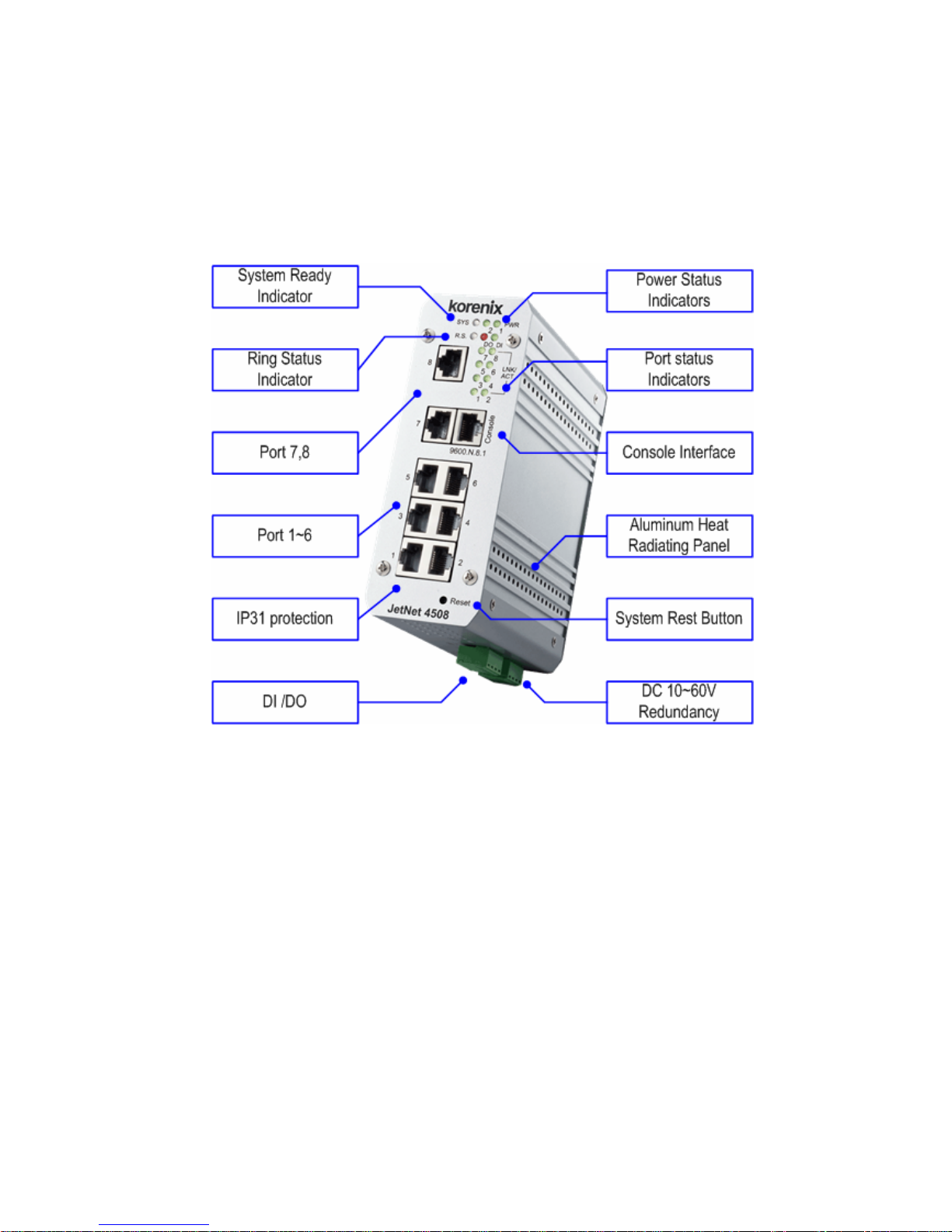
Front Panel Layout- JetNet 4508 V2
The front panel of JetNet 4508 V2 includes 8 10/100Mbps Fast Ethernet
RJ-45 ports, one RS-232 serial console in RJ-45 type connector, one reset
button and several of LED indicators for the system and port diagnostic. The
JetNet 4508V2 front panle shows as following diagram.
8
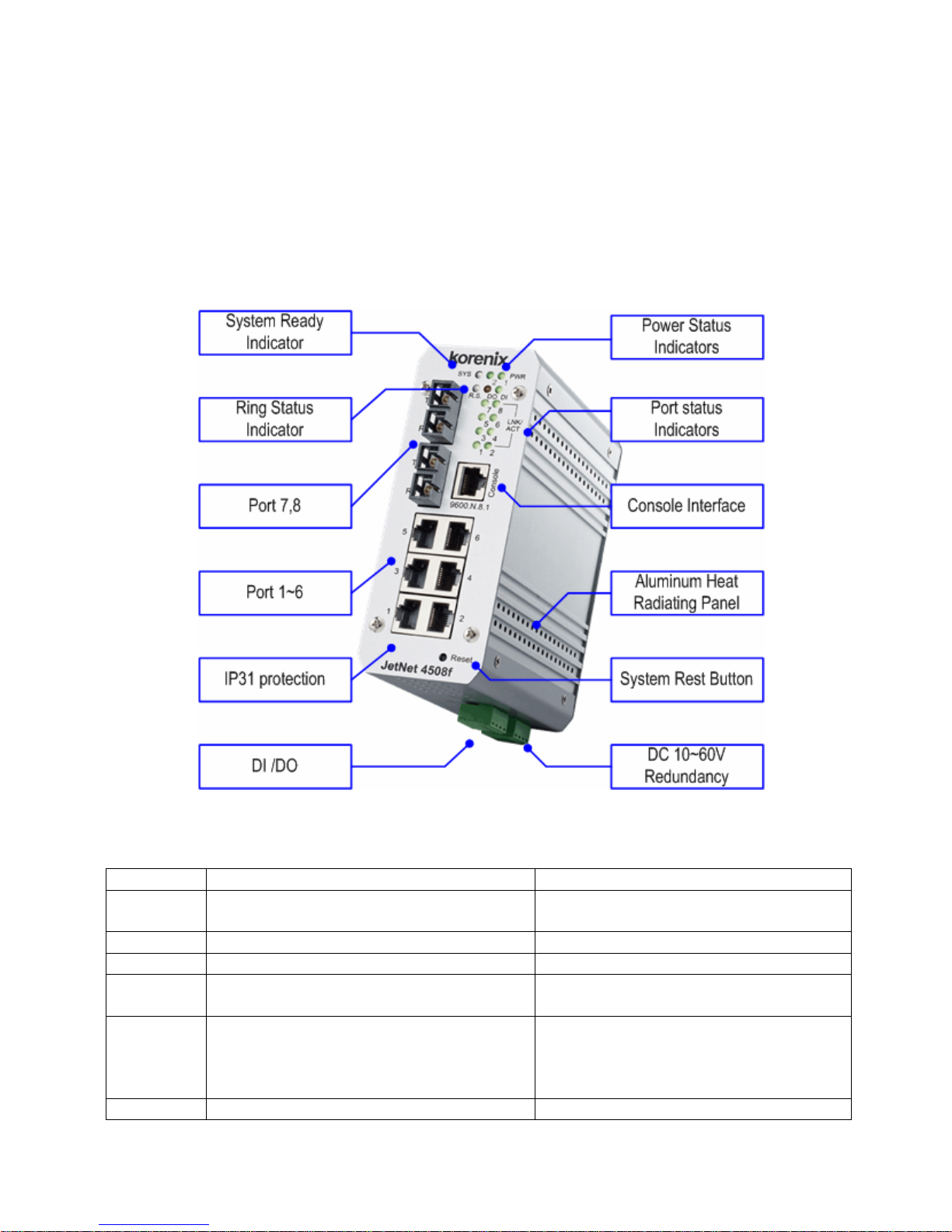
Front Panel Layout- JetNet 4508f V2
The front panel of JetNet 4508f V2 includes 6 10/100Mbps Fast Ethernet
RJ-45 ports (port 1~6), 2 Fast Ethernet fiber ports (port 7, 8), one RS-232
serial console in RJ-45 type connector, one reset button and several of LED
indicators for the system and port diagnostic. The JetNet 4508f V2 front
panle shows as following diagram.
The LED function is decribed as following table:
LED Function Behaviors
Power 1,2 Indicates the power input status On: the input connector is on applying
power.
SYS Indicates the system operating status On: System is ready to operating
DI Indicates the digital input status On: High level signal is applied
DO Indicates the digital output (Relay
output) status
Red On: the output is formed close
circuit
R.S. Indicates the ring operating status. Normal (Green on), Abnormal (Yellow
on), wrong ring port is connected
(Green blinking), one of device’s ring
path is broken (Yellow blinking)
Link/active Indicated the traffic status and link On: port is linked with partner.
9
status Blinking: the port is on transmitting or
receiving data.
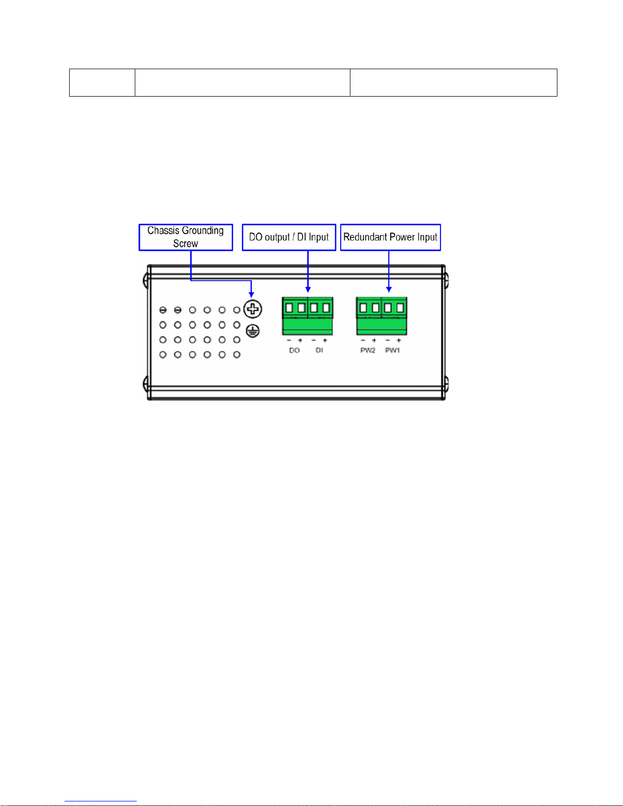
Bottom View
The bottom view of the JetNet 4508 V2 / JetNet 4508f V2 consists of two
terminal block connectors with two DC power inputs, one Digital Input (DI),
one Relay Output (DO) and one Chassis Grounding screw.
10
2.2 Wiring the Power Inputs
Follow below steps to wire JetNet 4508V2 /4508f V2 redundant DC power
inputs.
1. Insert positive and negative wires into V+ and V- contacts respectively of
the terminal block connector
2. T ighten the wire-clamp screws to prevent DC wires from being loosened.
3. Power 1 and Power 2 support power redundancy and polarity reverse
protect function. That means with wrong polarity, the system won’t work.
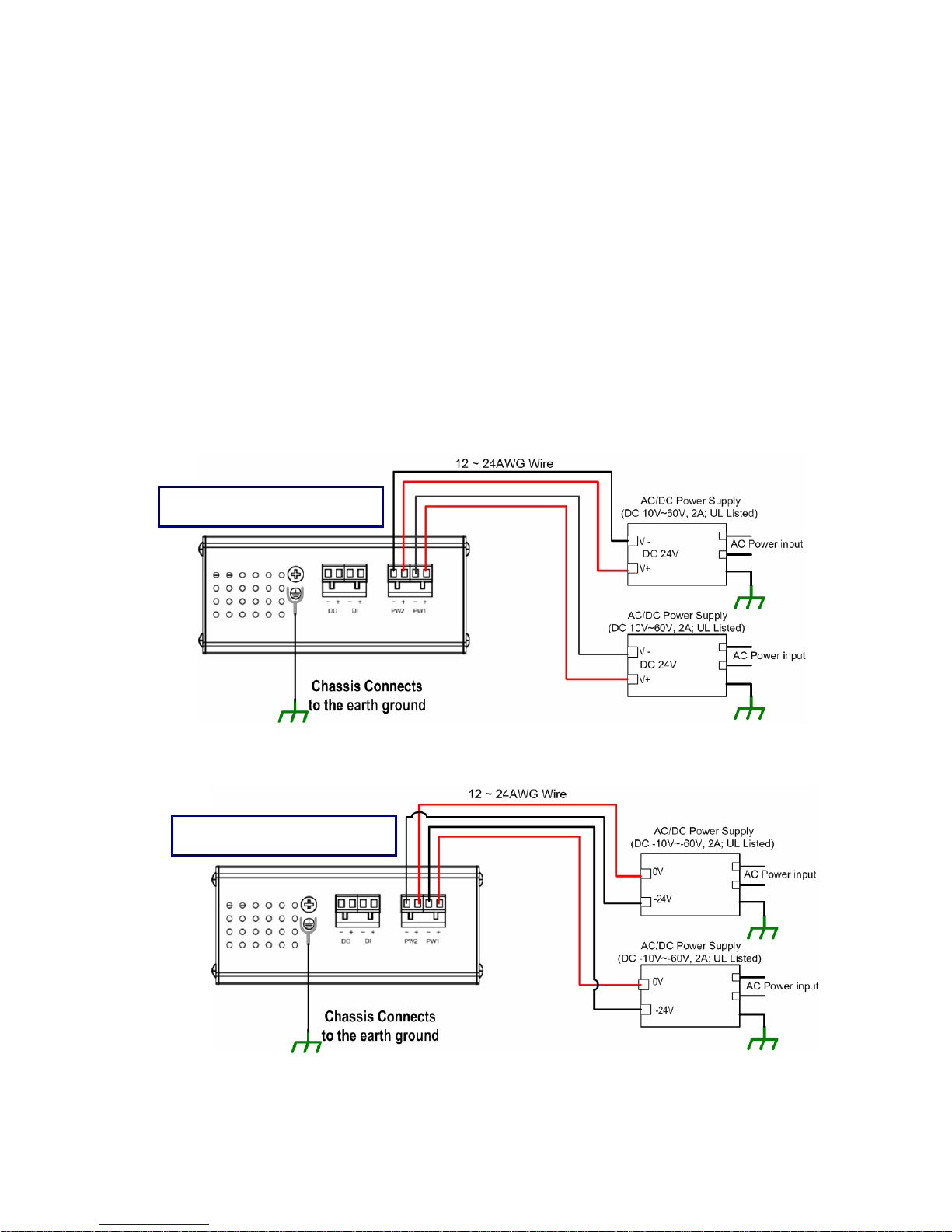
4. Positive and negative power system inputs are both accepted, but Power
1 and Power 2 must apply with same mode as following figures.
Positive Power wiring
Negative Power wiring

11
Note 1: It is a good practice to turn off input and load power, and to unplug
power terminal block before making wire connections. Otherwise, your
screwdriver blade can inadvertently short your terminal connections to the
grounded enclosure.
Note 2: The range of the suitable electric wire is from 12 to 24 AWG.
Note 3: If the 2 power inputs are connected, JetNet Switch will be powered
from the highest connected voltage. The unit will alarm for loss of power,
either PWR1 or PWR2 and auto backup with each other.
Note 4: Uses the UL Listed Power supply with output Rating 10-60 Vdc,
minimum 2 A. Here, we recommended use DC 24V as the operating voltage.
Note 5: Once the system powering on, the system diagnostic LEDs will
activate as the sequence shown in the following table:
Indicators Stage 1 Stage 2 Stage 3 Stage 4 Stage 5 Stage 6
Power LED On On On On On On
DI Off On Off Off Off Off
DO Off Off On Off Off Off
R.S. Off Off Off On Off Off
SYS Off Off Off Off Off On
Description Power on Ex. Booter Ld. firmware Ex. firmware System booting System Ready
By those LED indicators, we can know the exactly stage is performed during
the system power on.

12
2.3 Wiring Digital Input
JetNet 4508V2 series provide one digital input. It allows users to connect the
termination units’ digital output and manage/monitor the status of the connected
unit. The Digital Input pin can be pulled high or low; thus the connected
equipments can actively drive these pins high or low. The embedded software
UI allows you to read and set the value to the connected device.
The power input voltage of logic low is DC 0~10V. Logic high is DC
11~30V.
.
2.4 Wiring Digital Output
JetNet 4508 V2 series provide one digital output, also known as Dry Relay
Output. The relay contacts are energized (open) for normal operation and
will close for fault conditions. The fault conditions include power failure,
Ethernet port link break or other pre-defined events which can be
configured in JetNet 4508 Web user interface.

13
2.5 Wiring Earth Ground
To ensure the system will not be damaged by noise or any electrical shock,
we suggest you to make exact connection with JetNet 4508 V2 series with
Earth Grounding.
On the bottom side of JetNet 4508 V2 series, there is one earth ground
screw. Loosen the earth ground screw by screw drive; then tighten the
screw after earth ground wire is well connected.
Without the exact system chassis grounding, the communication may
intereferred by the external noise, such as lighting, fast electrical filed
transient or electrostatic discharge.
14
2.6 Wiring Fast Ethernet RJ-45 Ports
The JetNet 4508 V2 series adopts several of RJ-45 connectors which
support 10/100Base-TX with link speed auto negotiation and auto
MDI/MDI-X functions.
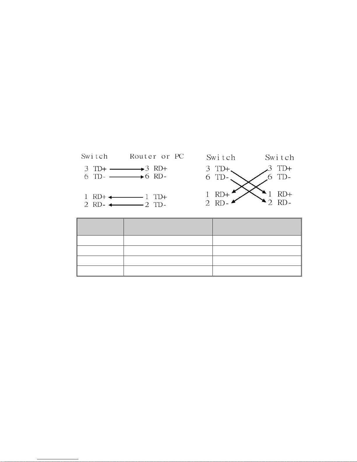
All the RJ-45 ports will auto-detect the signal from connected devices to
negotiate the link speed and duplex mode. Auto MDI/MDIX allows users to
connect another switch, hub or workstation without changing straight
through or crossover cable.
Note: that crossover cables simply cross-connect the transmit lines at
each end to the received lines at the opposite end.
Pin MDI-X Signals MDI Signals
1 RD+ TD+
2 RD- TD3 TD+ RD+
6 TD- RD-
Connect one side of an Ethernet cable into any switch port and connect the
other side to your attached device. The LNK LED will light up when the
cable is correctly connected. Refer to the LED Indicators section for
descriptions of each LED indicator. Always make sure that the cables
between the switches and attached devices (e.g. switch, hub, or
workstation) are less than 100 meters (328 feet).
The supported cable types listed as below:
100Base-TX: 4-pair UTP/STP Cat. 5 Cable, EIA/TIA-568B 100-ohm (100 meters)
10Base-T: 4-pair UTP/STP Cat.3, 4 cable, EIA/TIA-568B 100-ohm (100meters)
15
2.7 Wiring Fast Ethernet Fiber port (JetNet 4508f V2)
JetNet 4508f V2 equipped 2 ports fiber which compliance with IEEE 802.3
100Base-FX standard and supports multi-mode or single mode fiber cable.
The fiber connector supports SC type connector and for the other type
connector, please contacts your Korenix distributor for more information.
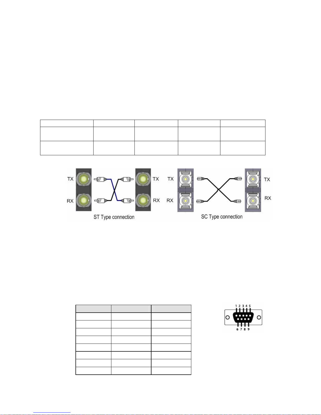
To ensure the quality of connection, the specifications of cable and fiber
port must matched; with wrong fiber cable may caused the communication
does not work well.The following information is the specification includes
suitable cable and the characteristics of fiber port.
Model TX power RX sensitivity Wavelength Fiber Cable
JetNet 4508f-s V2,
30KM
-8~-15 dBm -31~-14dBm 1310nm 8~10/125 um
Single mode
JetNet 4508f-m V2
2KM
-14~-31 dBm -14~-31 dBm 1310nm 50~62.5/125um
Multi-mode
2.8 Wiring RS-232 Console Cable
There is one RS-232 DB-9 to RJ-45 cable shipped with the box. Connects
the DB-9 connector to the COM port of your PC, open Terminal tool and
configure the serial communication parameter to 9600, N, 8, 1. (Baud Rate:
9600bps / Parity: None / Data length: 8bits / Stop Bit: 1) Then you can
access CLI interface by console able.
Note: If you lost the cable, please contact with your sales or follow the pin
assignment to buy a new one. The Pin assignment spec is listed following.
RJ-45 Pin DB-9 Pin Description
1 7 N/A
2 9 N/A
3 4 TxD
4 5 N/A
5 1 GND
6 3 RxD
7 2 N/A
8 8 N/A
16
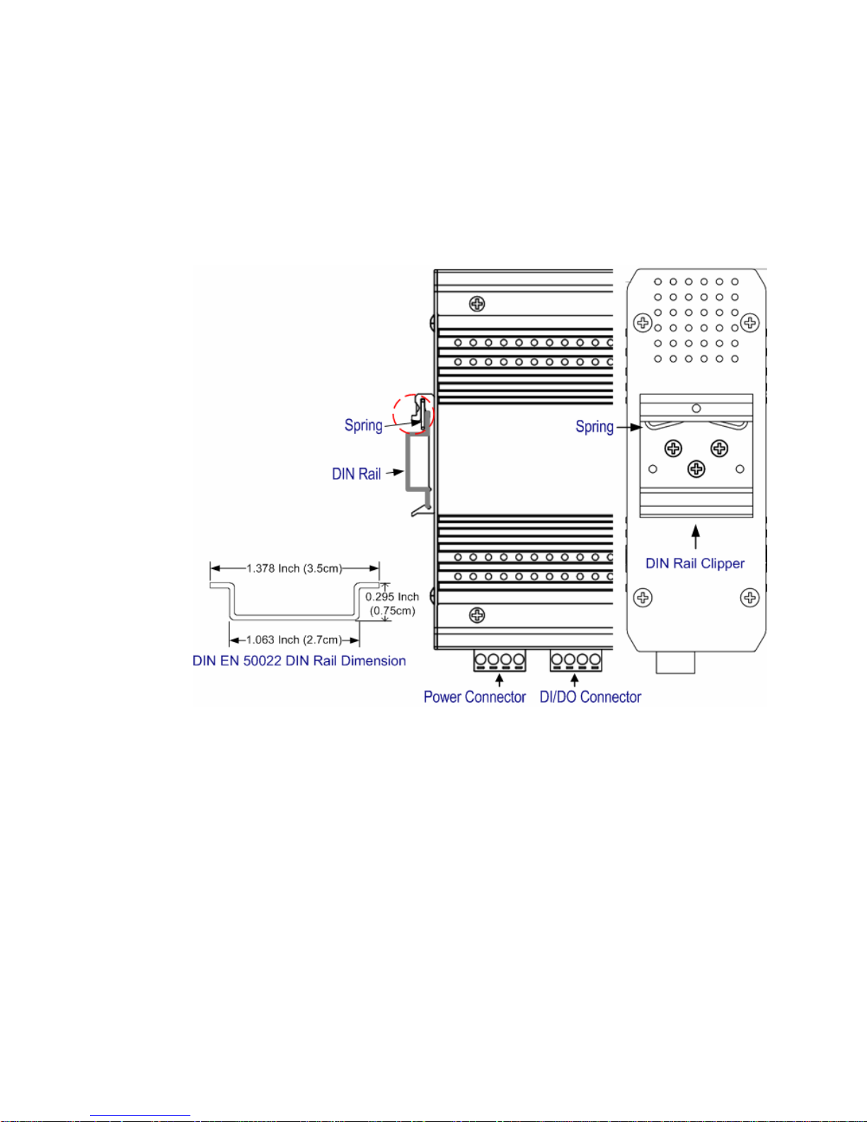
2.9 DIN-Rail Mounting Installation
The DIN-Rail clip is already screwed tighten on the rear side of JetNet
JetNet 4508V2/ JetNet 4508f V2 when shipping. If the DIN-Rail clip is not
screwed on the JetNet 4508 V2/ JetNet 4508f V2, please contact your
distributor to get the DIN rail clip set. The DIN rail clip supports EN50022
standard. In the diagram following includes the dimension of EN50022 DIN
rail for your refer.
Follow the steps below to mount JetNet Managed Switch to the DIN-Rail
track:
1. First, insert the DIN-Rail track upper side into the upper end of
DIN-Rail clip.
2. Lightly push the bottom of DIN-Rail clip into the track.
3. Check if DIN-Rail clip is tightly attached on the track.
4. To remove JetNet 4508V2/ JetNet 4508f V2 from the track, reverse
the steps above.
Notes: The DIN Rail should compliance with DIN EN50022 standard. Using wrong
DIN rail may cause system install unsafe.

17
3 Preparation for Management
JetNet 4508 V2 / 4508f V2 series Industrial Managed Fast Ethernet
Switch provides both in-band and out-band configuration methods. You
can configure the switch via RS232 console port via serial cable attached
in the package if you don’t attach your admin PC to your network, or if you
lose network connection to the target JetNet Switch. This is so-called
out-band management. It wouldn’t be affected by network performance.
The in-band management means you can remotely manage the switch
via the Ethernet network. You can choose Telnet or Web-based
management. You just need to know the device’s IP address and you can
remotely connect to its embedded HTTP web pages or Telnet console.
Following topics are covered in this chapter:
3.1 Preparation for Serial Console
3.2 Preparation for Web Interface
3.3 Preparation for Telnet console

18
3.1 Preparation for Serial Console
In package, Korenix attached one RS-232 DB-9 to RJ-45 console cable.
Please attach RS-232 DB-9 connector to your PC COM port, connect
RJ-45 to the Console port of the JetNet Switch. If you lose the cable,
please follow the console cable PIN assignment to find one. (Refer to
session 2.8).
1. Go to Start -> Program -> Accessories -> Communication -> Hyper
Terminal
2. Give a name to the new console connection.
3. Choose the COM name
4. Select correct serial settings. The serial settings of JetNet 4508 V2
/4508f V2 are as below:
Baud Rate: 9600 / Parity: None / Data Bit: 8 / Stop Bit: 1
5. After connected, you can see Switch login request.
6. Login the switch. The default username is “admin”, and password is
“admin”.
Boot Loader Rev 1.0.0.4 for JetNet4508fV2 (Sep 2 2010 - 17:48:54)
Loading firmware ...
Excuting firmware ...
Booting ........................................................................
....
Validate hardware : Success
System start type : Watchdog reset
Switch MAC address : 00:12:77:FF:00:00
Port6 Link Change to UP
Port5 Link Change to UP
Loading system : Success
Port5 Link Change to DOWN
RF's TestinPort5 Link Change to UP
g login:
19
3.2 Preparation for Web Interface
JetNet 4508 V2/4508f V2 provides HTTP Web Interface and Secured
HTTPS Web Interface for web management.
3.2.1 Web Interface
Korenix web management page is developed by JAVA. It allows you to
use a standard web-browser such as Microsoft Internet Explorer, or
Mozila, to configure and interrogate the switch from anywhere on the
network.
Before you attempt to use the embedded web interface to manage switch
operation, verify that your JetNet 4508 V2/ 4508f V2 is properly installed
on your network and that every PC on this network can access the switch
via the web browser.
1. Verify that your network interface card (NIC) is operational, and that
your operating system supports TCP/IP protocol.
2. Wire DC power to the switch and connect your switch to your
computer.
3. Make sure that the switch default IP address is 192.168.10.1.
4. Change your computer IP address to 192.168.10.2 or other IP
address which is located in the 192.168.10.x (Network Mask:
255.255.255.0) subnet.
5. Switch to DOS command mode and ping 192.168.10.1 to verify a
normal response time.
Launch the web browser and Login.
6. Launch the web browser (Internet Explorer or Mozila Firefox) on the
PC.
7. Type http://192.168.10.1 (or the IP address of the switch). And then
press Enter.
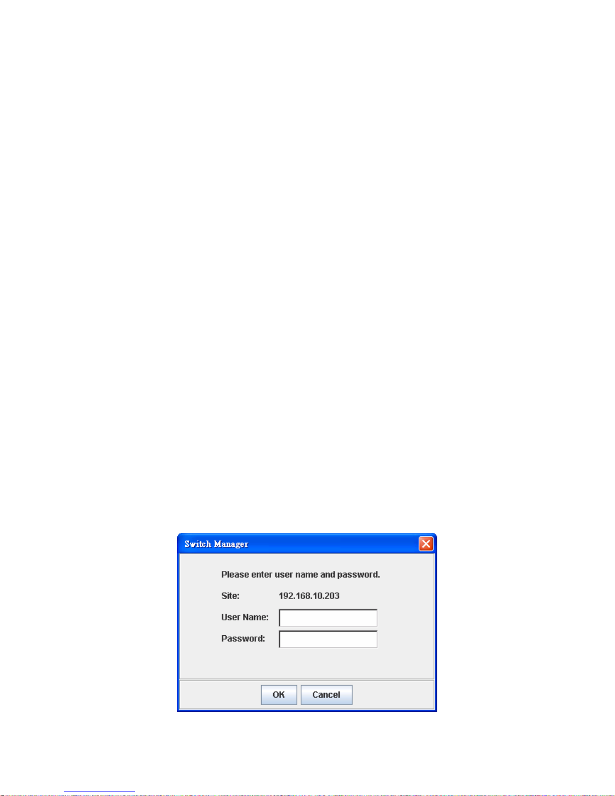
8. The login screen will appear next.
9. Key in user name and the password. Default user name and
password are both admin.
20
Click on Enter or OK. Welcome page of the web-based management
interface will then appear.
Once you enter the web-based management interface, you can freely
change the JetNet’s IP address to fit your network environment.
Note 1: IE 5.0 or later versions do not allow Java applets to open sockets
by default. Users have to directly modify the browser settings to
selectively enable Java applets to use network ports.
Note 2: The Web UI connection session of JetNet Switch will be logged
out automatically if you don’t give any input after 30 seconds. After logged
out, you should re-login and key in correct user name and password
again.
3.2.2 Secured Web Interface
Korenix web management page also provides secured management
HTTPS login. All the configuration commands will be secured and will be
hard for the hackers to sniff the login password and configuration
commands.
Launch the web browser and Login.
1. Launch the web browser (Internet Explorer or Mozila Firefox) on the
PC.
2. Type https://192.168.10.1 (or the IP address of the switch). And then
press Enter.
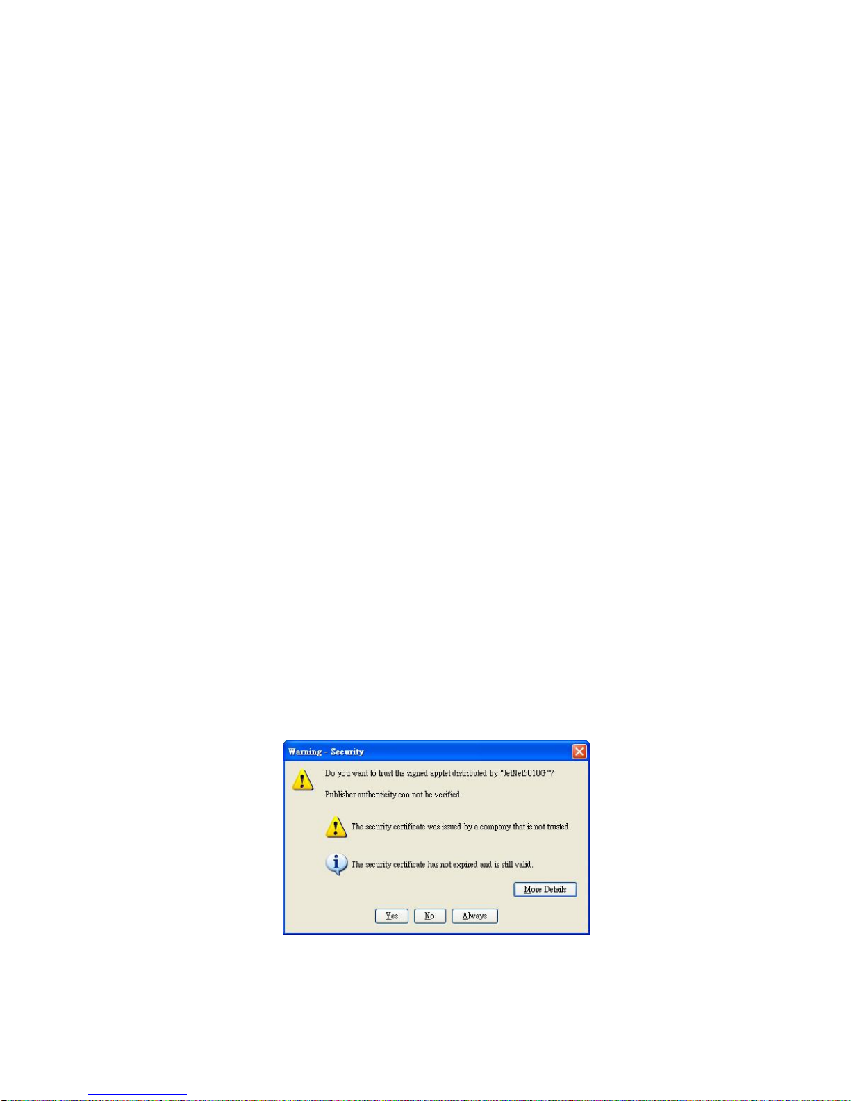
3. The popup screen will appear and request you to trust the secured
HTTPS connection distributed by JetNet 4508 V2/JetNet 4508f V2
first. Press Yes to trust it. ( Uses JeNet 5010G sample)
21
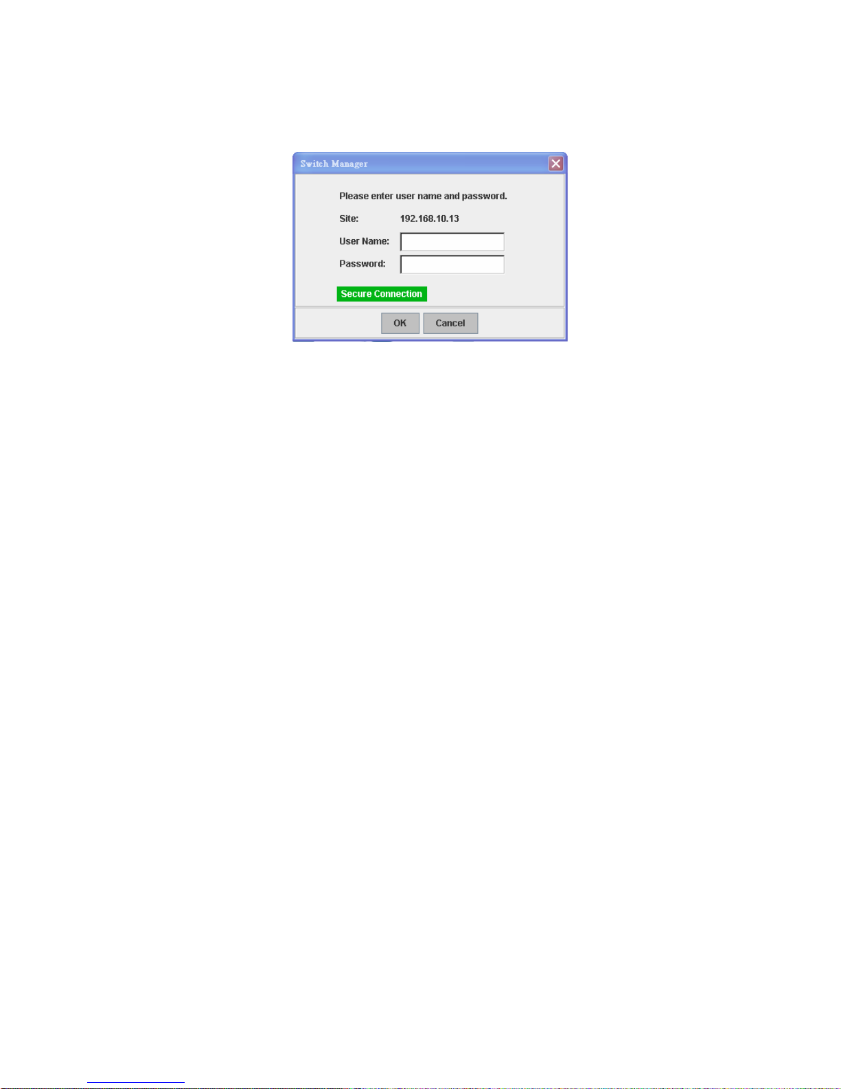
4. The login screen will appear next.
5. Key in the user name and the password. The default user name and
password is admin.
6. Click on Enter or OK. Welcome page of the web-based management
interface will then appear.
7. Once you enter the web-based management interface, all the
commands you see are the same as what you see by HTTP login.
22
3.3 Preparation for Telnet Console
3.3.1 Telnet
Korenix JetNet 4508 V2/ 4508f V2 supports Telnet console. You can
connect to the switch by Telnet and the command lines are the same as
what you see by RS-232 console port. Below are the steps to open Telnet
connection to the switch.
1. Go to Start -> Run -> cmd. And then press Enter
2. Type the Telnet 192.168.10.1 (or the IP address of the switch). And
then press Enter
3.3.2 SSH (Secure Shell)
Korenix JetNet 4508 V2/ 4508f V2 also support SSH console. You can
remotely connect to the switch by command line interface. The SSH
connection can secure all the configuration commands you sent to the
switch.
SSH is a client/server architecture while JetNet 4508 V2/ 4508f V2 is the
SSH server. When you want to make SSH connection with the switch,
you should download the SSH client tool first.
SSH Client
There are many free, sharewares, trials or charged SSH clients you can
find on the internet. Fox example, PuTTY is a free and popular
Telnet/SSH client. We’ll use this tool to demonstrate how to login JetNet
by SSH. Note: PuTTY is copyright 1997-2006 Simon Tatham.
Download PuTTY:
http://www.chiark.greenend.org.uk/~sgtatham/putty/download.html
The copyright of PuTTY
23
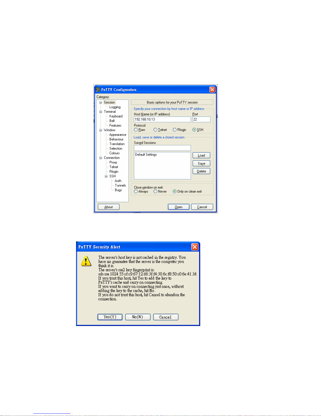
1. Open SSH Client/PuTTY
In the Session configuration, enter the Host Name (IP Address of your
JetNet Switch) and Port number (default = 22). Choose the “SSH”
protocol. Then click on “Open” to start the SSH session console.
(The sample’s IP address is 192.168.10.13)
2. After click on Open, then you can see the cipher information in the
popup screen. Press Yes to accept the Security Alert.
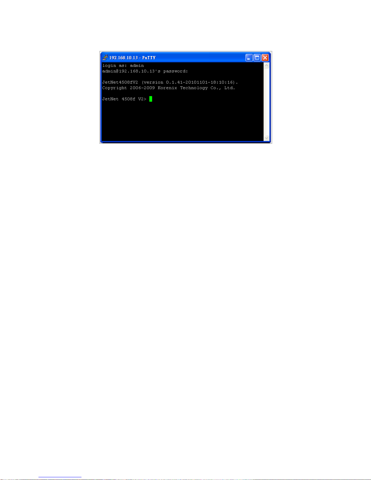
3. After few seconds, the SSH connection to JetNet 4508 V2/ 4508f V2 is
opened. You can see the login screen as the below figure.
24
4. Type the Login Name and its Password. The default Login Name and
Password are admin / admin.
5. All the commands you see in SSH are the same as the CLI
commands you see via RS232 console. The next chapter will
introduce in detail how to use command line to configure the switch.

25
4 Feature Configuration
This chapter explains how to configure JetNet 4508 V2/4508f V2 software
features. There are four ways to access the switch: Serial console, Telnet,
Web browser and SNMP.
JetNet 4508 V2/4508f V2 series Industrial Managed Switch provides both
in-band and out-band configuration methods. You can configure the switch
via RS-232 console cable if you don’t attach your admin PC to your network,
or if you lose the network connection to your JetNet JetNet 4508 V2/JetNet
4508f V2. This is so-called out-band management. It wouldn’t be affected
by the network performance.
The in-band management means you can remotely manage the switch via
the network. You can choose Telnet or Web-based management. You just
need to know the device’s IP address. Then you can remotely connect to its
embedded HTML web pages or Telnet console.
Korenix web management page is developed by JAVA. It allows you to use
a standard web-browser such as Microsoft Internet Explorer, or Mozila, to
configure and interrogate the switch from anywhere on the network.
Note: IE 5.0 or later versions do not allow Java applets to open sockets by
default. Users have to directly modify the browser settings to selectively
enable Java applets to use network ports.
Following topics are covered in this chapter:
4.1 Command Line Interface (CLI) Introduction
4.2 Basic Setting
4.3 Port Configuration
4.4 Network Redundancy
4.5 VLAN
4.6 Traffic Prioritization
4.7 Multicast Filtering
4.8 SNMP
4.9 Security
4.10 Warning
4.11 Monitor and Diag
4.12 Device Front Panel
4.13 Save
4.14 Logout

26
4.1 Command Line Interface Introduction
The Command Line Interface (CLI) is the user interface to the switch’s
embedded software system. You can view the system information, show
the status, configure the switch and receive a response back from the
system by keying in a command.
There are some different command modes. Each command mode has its
own access ability, available com m and lines and uses different command
lines to enter and exit. These modes are User EXEC, Privileged EXEC,
Global Configuration, (Port/VLAN) Interface Configuration modes.
User EXEC mode: As long as you login the switch by CLI. You are in the
User EXEC mode. You can ping, telnet remote device, and show some
basic information.
Type enable to enter next mode, exit to logout. ? to see the command list
Privileged EXEC mode: Press enable in the User EXEC mode, then you
can enter the Privileged EXEC mode. In this mode, the system allows you
to view current configuration, reset default, reload switch, show system
information, save configuration…and enter the global configuration mode.
Type configure terminal to enter next mode, exit to leave. ? to see the
command list
Switch>
enable Turn on privileged mode command
exit Exit current mode and down to previous mode
list Print command list
ping Send echo messages
quit Exit current mode and down to previous mode
show Show running system information
telnet Open a telnet connection
traceroute Trace route to destination
Switch#
archive manage archive files
clear Reset functions
clock Configure time-of-day clock
configure Configuration from vty interface
copy Copy from one file to another
debug Debugging functions (see also 'undebug')
disable Turn off privileged mode command
end End current mode and change to enable mode
exit Exit current mode and down to previous mode
list Print command list
more Display the contents of a file
no Negate a command or set its defaults
ping Send echo messages
quit Exit current mode and down to previous mode
reboot Reboot system
reload copy a default-config file to replace the current one
show Show running system information
telnet Open a telnet connection
terminal Set terminal line parameters
traceroute Trace route to destination
write Write running configuration to memory, network, or terminal
 Loading...