

Korenix JetNet 4000, JetNet 4000 Series User Manual

Korenix JetNet 4000 Series
Industrial Ethernet Rail Switch
User ’s Manual
Third Edition, September 2005
www.korenix.com

Korenix JetNet 4000 Series
Industrial Ethernet Rail Switch
User’s Manual
Copyright Notice
Copyright © 2005 Korenix Technology Co., Ltd.
All rights reserved.
Reproduction in any form or by any means without permission is prohibited.

Table of Contents
Chapter 1 Introduction.............................................................................................1-1
Overview...........................................................................................................1-2
Ethernet Switching Technology........................................................................1-2
Product Features..............................................................................................1-2
Package Checklist............................................................................................1-3
Chapter 2 Hardware Installation..............................................................................2-1
Introduction....................................................................................................... 2-2
Panel Layout ....................................................................................................... 2-2
Reset Button........................................................................................................ 2-2
LED Indicators.................................................................................................... 2-2
DIP Switch.......................................................................................................... 2-4
Wiring the Power Inputs ................................................................................... 2-4
Wiring the Relay Output ................................................................................... 2-4
Wiring the Ethernet Ports ................................................................................. 2-5
Wiring the Fiber Ports....................................................................................... 2-6
DIN-Rail Mounting Installation..........................................................................2-6
Wall-Mounting Installation ................................................................................ 2-7
Chapter 3 Web-based Management........................................................................3-1
Introduction....................................................................................................... 3-2
Preparation for Web Management ................................................................... 3-2
System Login.................................................................................................... 3-2
Start Using Web-based Management Interface to Configure...........................3-3
Menu Bar Introduction........................................................................................ 3-3
Configuring Your JetNet 4000............................................................................ 3-4
Chapter 4 Troubleshooting......................................................................................4-1
Incorrect Connections.......................................................................................4-2
Faulty or Loosen Cables ..................................................................................... 4-2
Non-standard Cables........................................................................................... 4-2
Improper Network Technologies ........................................................................ 4-2
LED Indicators..................................................................................................4-2
Appendix A Specifications.........................................................................................A-1
Appendix B Revision History..................................................................................... B-1

11
Chapter 1 Introduction
Welcome to Korenix JetNet 4000 Series Industrial Ethernet Rail Switch. JetNet 4000 Series is a
web-managed rail switch that is specially designed for industrial applicatio ns.
The following topics are covered in this chapter:
Overview
Ethernet Switching Technology
Product Features
Package Checklist
Installation Guide

Korenix JetNet 4000 Series Industrial Web-Managed Ethernet Rail Switch User’s Manual
1-2
Overview
JetNet 4000 Series is a web-managed rail switch that is specially designed for industrial
applications. JetNet 4000 uses one-piece formed aluminum case that complies with IP31
industrial standard, allowing JetNet 4000 to operate under harsh industrial environments. JetNet
4000 provides dual DC power inputs, ensuring your systems to run non-stop. JetNet 4000 also
supports Super Ring technology, which can offer you industrial-grade redundant network
solution. When your primary path fails, the entire system can still function normally with the
secondary path activated. JetNet 4000 supports fiber connectors, effectively extending switches’
transmission distance. Web-based management interface ensures easy management by using
web browser over the network.
Ethernet Switching Technology
Ethernet Switching Technology dramatically boosted the total bandwidth of a net work, eliminated
congestion problems inherent with CSMA/CD (Carrier Sense multiple access with Collision
Detection) protocol, and greatly reduced unnecessary transmissions.
This revolutionized networking. First, by allowing two-way, simultaneous transmissions over the
same port (Full-duplex), which essentially doubled the bandwidth. Second, by reducing the
collision domain to a single switch-port, which eliminated the need for carrier sensing. Third, by
using the store-and-forward technology’s approach of inspecting each packet to intercept corrupt
or redundant data, switching eliminated unnecessary transmission that slow the network. By
employing address learning, which replaced the inefficient receiving port.
Auto-negotiation regulates the speed and duplex of each port, based on the capability of both
devices. Flow-control allows transmission from a 100Mbps node to a 10Mbps node without loss
of data. Auto-negotiation and flow-control may require disablement for some networking
operations involves legacy equipment. Disabling the auto-negotiation is accomplished by fixing
the speed or duplex of a port.
Ethernet Switching Technology supplied higher performance at costs lower than other solutions.
Wider bandwidth, no congestion, and the reduction in traffic is why switching is replacing
expensive routers and inefficient hubs as the ultimate networking solution. Switching brought a
whole new way of thinking to networking.
Product Features
Korenix JetNet 4000 Series products have the following features:
Redundant Ethernet Super Ring
Supports VLAN/QoS/IGMP Snooping
Web-based Configuration
Redundant DC Power Inputs
Alarm Relay Output
Robust Aluminum case, IP31 standard
DIN-Rail/Wall-mounting/Desktop Installation
5/8 10/100TX ports for JetNet 4005/4008
4/6 10/100TX ports and 1/2 100FX port(s) for JetNet 4005f/4008f
Conforms to IEEE 802.3 10Base-T, 802.3u 100Base-TX/100Base-FX
RJ-45 ports support auto MDI/MDI-X function
Store-and-Forward switching architecture
Introduction
Korenix JetNet Series Industrial Web-Managed Ethernet Rail Switch User’s Manual
1-3
Web management GUI
Provides Fiber link ability
IEEE 802.3x flow control supported
¾ Flow control on full-duplex mode
¾ Back pressure on half-duplex mode
Supports Class of Service
Supports IGMP with Query mode for multi media application
Supports broadcast packet filtering
Supports SNTP
Provides reverse polarity protection
1Mbits embedded memory
2K MAC address table
Supports port-based VLAN / 802.1 Q Tag VLAN
Package Checklist
Korenix JetNet 4000 Series products are shipped with the following items:
1 Korenix Industrial Web-Managed Ethernet Rail Switch
One DIN-Rail clip (attached with the JetNet switch)
One wall mounting plate and six screws
Documentation and Software CD
Quick Installation Guide
If any of the above items is missing or damaged, please contact your local sales representative.

22
Chapter 2 Hardware Installation
This chapter includes information of installation and configuration.
The following topics are covered in this chapter:
Introduction
¾ Panel Layout
¾ Reset Button
¾ LED Indicators
¾ DIP Switch
Wiring the Power Inputs
Wiring the Relay Output
Wiring the Ethernet Ports
Wiring the Fiber Ports
DIN-Rail Mounting Installation
Wall-Mounting Installation
Korenix JetNet 4000 Series Industrial Web-Managed Ethernet Rail Switch User’s Manual
2-2
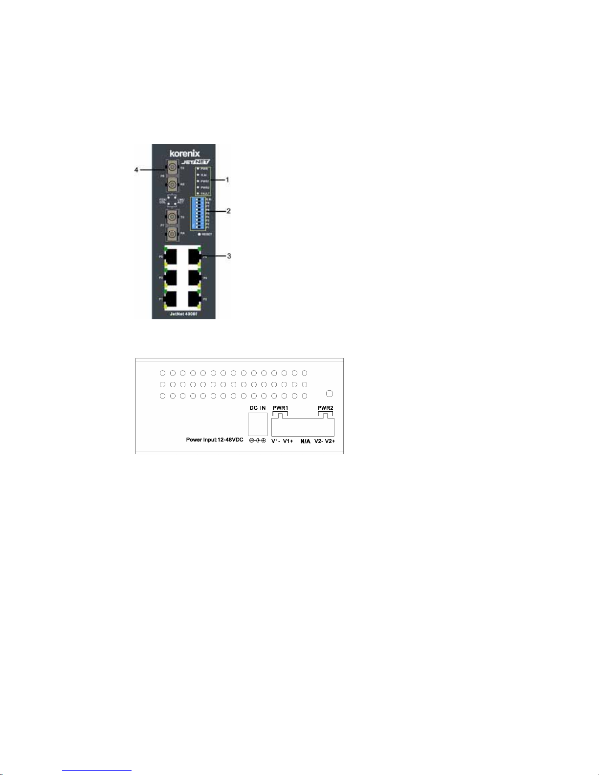
Introduction
Panel Layout
Here we use JetNet 4008f as an example.
Front View
1 LED indicators
2 DIP switch
3 RJ-45 ports
4 Fiber ports
Bottom View
The bottom view of the JetNet 4000
Series Industrial Web-Managed
Ethernet Rail Switch consists of one
terminal block connector with two DC
power inputs and one DC IN power
jack for an additional AC/DC power
adapter.
Reset Button
The Reset button provides users with a quick and easy way to restart JetNets and restore the
default settings.
To restart: press the Reset button for 2 seconds and release.
To restore the default settings: press the button for 5 seconds and release.
LED Indicators
There are 7 diagnostic LEDs and 8 Port LEDs located on the front panel of JetNet 4005, while
there are 9 diagnostic LEDs and 12 Port LEDs on JetNet 4008. Industrial Ethernet Rail Switch.
These LED indicators provide administrators with real-time system status. Table 1 gives
descriptions of the function of each LED indicator.
Hardware Installation
Korenix JetNet Series Industrial Web-Managed Ethernet Rail Switch User’s Manual
2-3
LED Status Description
Green Power is on.
PWR
Off No power is being supplied.
Green Power is on.
PWR 1
Off No power is being supplied.
Green Power is on.
PWR 2
Off No power is being supplied.
Green
Indicates that this JetNet is the master of the
Super Ring.
R.M
Off
Indicates that this JetNet is NOT the master of
the Super Ring.
Yellow Power, or UTP port, or fiber port failure occurs.
Fault
Off
No power, or UTP port, or fiber port failure
occurs.
Port LED Status Description
Green A network device is dete cted.
Blinks
The port is transmitting or receiving packets from
the TX device.
LNK/ACT of Port 7
(JetNet 4008f)
Off No device is attached.
Orange The port is operating in full-duplex mode.
Blinks Collision of packets occurs.
FDX/COL of Port 7
(JetNet 4008f)
Off
The port is in half-duplex mode or no device is
attached.
Green A network device is dete cted.
Blinks
The port is transmitting or receiving packets from
the TX device.
LNK/ACT of Port 5
(JetNet 4005f)
LNK/ACT of Port 8
(JetNet 4008f)
Off No device is attached.
Orange The port is operating in full-duplex mode.
Blinks Collision of packets occurs.
FDX/COL of Port 5
(JetNet 4005f)
FDX/COL of Port 8
(JetNet 4008f)
Off
The port is in half-duplex mode or no device is
attached.
Orange The port is operating in full-duplex mode.
Blinking
orange
Collision of Packets occurs.
Off
The port is in half-duplex mode or no device is
attached.
Green A network device is dete cted.
Blinking
green
The port is transmitting or receiving packets from
the TX device.
Port Status
Off No device is attached.
Korenix JetNet 4000 Series Industrial Web-Managed Ethernet Rail Switch User’s Manual
2-4
DIP Switch
The DIP switch is used to configure which JetNet in a Super Ring to be a master switch.
DIP SWITCH Status Description
ON Set this switch to be the Ring Master.
R.M.
Off Set this switch NOT to be the Ring Master.
ON To enable port break alarm on each port.
P1 to P8 (JetNet 4008f)
P1 to P5 (JetNet 4005f)
Off To disable port break alarm.
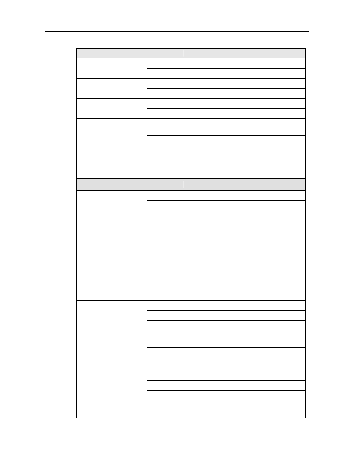
Wiring the Power Inputs
1. Insert the positive and negative wires into the V+ and V- contact on the terminal block
connector.
2. Tighten the wire-clamp screws to prevent the DC wires from being loosened.
Note: The suitable electric wire ranges from 12 to 24 AWG.
Note: The additional power jack is designed for office use.
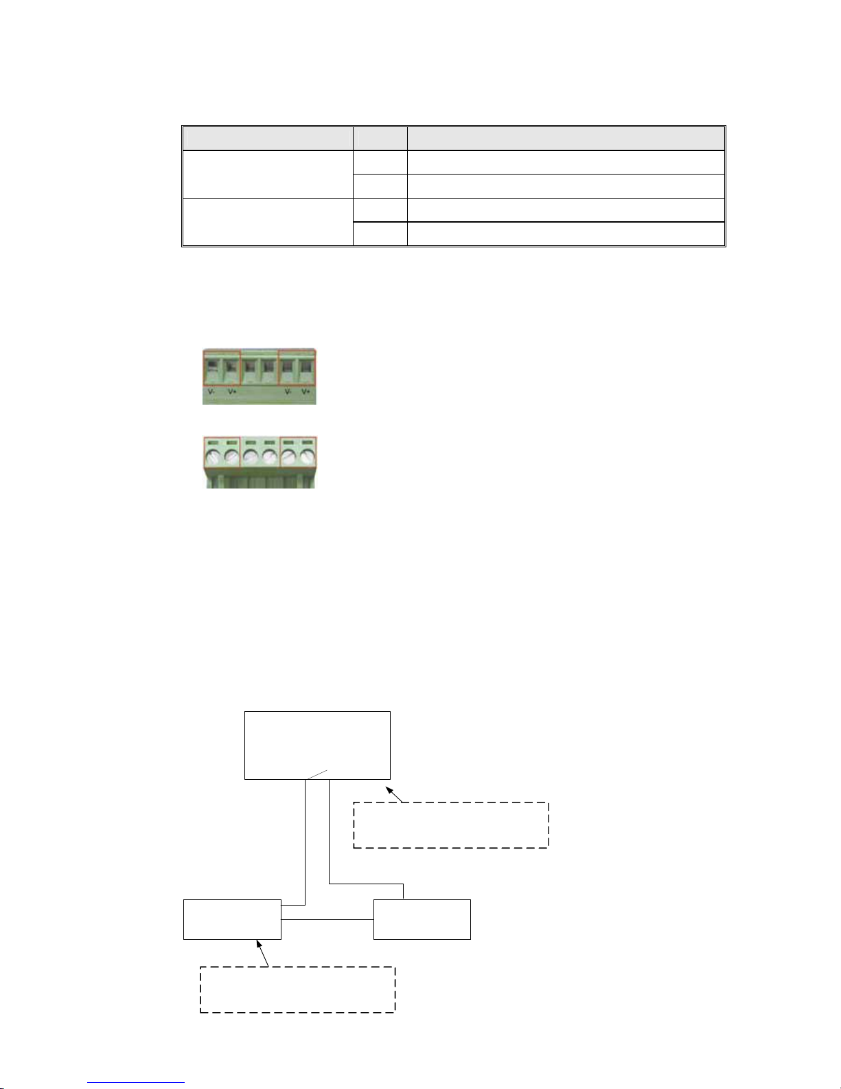
Wiring the Relay Output
The relay output alarm contacts are in the middle of the terminal block connector as shown in the
figure below. By inserting the wires and set the DIP switch to “ON”, relay output alarm will detect
any power or port failures, and form an open circuit. The figure below illustrates an example of
how relay output alarm works.
Note: The connection point of alarm relay output only switches on and off the circuit. It does not
supply any power. The connection point can only bear 1A@DC24V.
Fault Alarm Contact
24V DC Buzzer 24V Ba tte ry
The open circuit will form when the
power failure or port link failure.
The fault alarm device will send a
warning signal to warn the user, ex:
alarm sound or flash light.
Hardware Installation
Korenix JetNet Series Industrial Web-Managed Ethernet Rail Switch User’s Manual
2-5
1. Insert the alarm device’s negative wire into assigned position of the terminal block connector.
2. Tighten the wire-clamp screws to prevent the wires from being loosened.
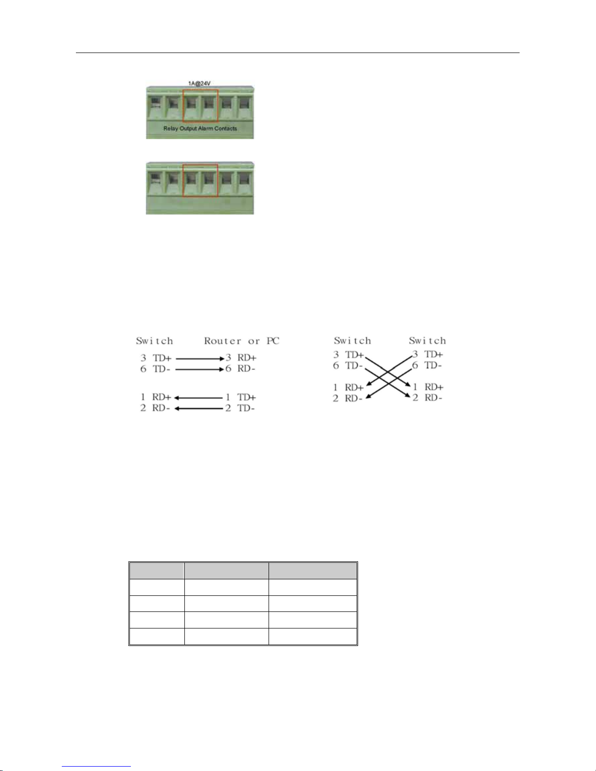
Wiring the Ethernet Ports
RJ-45 ports with auto MDI-MDI-X function: JetNet 4008 has eight 10/100 Mbps auto-sensing
ports for 10Base-T or 100Base-TX device connection. The UTP ports will auto-detect 10Base-T
and 100Base-TX connections. Auto MDI/MDI-X function allows users to connect another switch
or workstation without changing straight-through or cross-over cabling. See the figures below for
the schematic diagram of straight-through and cross-over cabling.
Straight-through Cabling Schematic Cross-over Cabling Schematic
Use four twisted-pair Category 5 cables for RJ-45 port connection. Connect one side of an
Ethernet cable into the JetNet’s TX port, while the other side is connected to the attached device.
The LED will light up when the cable is correctly connected. Refer to the LED Indicators section
for descriptions of the function of each LED indicators. The cables between the JetNet and the
attached device (e.g. switch, hub, or workstation) must be less than 100 meters (328 ft.).
All ports of JetNet 4000 support auto-MDI/MDI-X function. When you use an Ethernet cable to
connect other devices, such as computers, switches or hubs, pin 1, 2, 3, and 6 of the 8-pin RJ45
connector are used to communicate with the connected devices. Pin1, 2, 3, and 6’s signals are
converted by the MDI-X function, as shown in the table below.
Pin MDI-X Signals MDI Signals
1 RD+ TD+
2 RD- TD3 TD+ RD+
6 TD- RD-
Two switches are now up-linked together. If we change the up-link port man ually at this time,
MAC address table will change as well. After MAC address table makes the changes, and then
the data can be transmitted between these two switches. This period of time is called MAC
address table aging time. Korenix JetNet 4000’s default aging time is 5 minutes, which means
that if you manually change the up-link port, you will need to wait for 5 minutes before the data
Korenix JetNet 4000 Series Industrial Web-Managed Ethernet Rail Switch User’s Manual
2-6
can be sent. If the aging time is too short, MAC address table will constantly refresh, resulting in
large consumption of the switch’s computing resources. For this reason, longer aging time is
recommended.
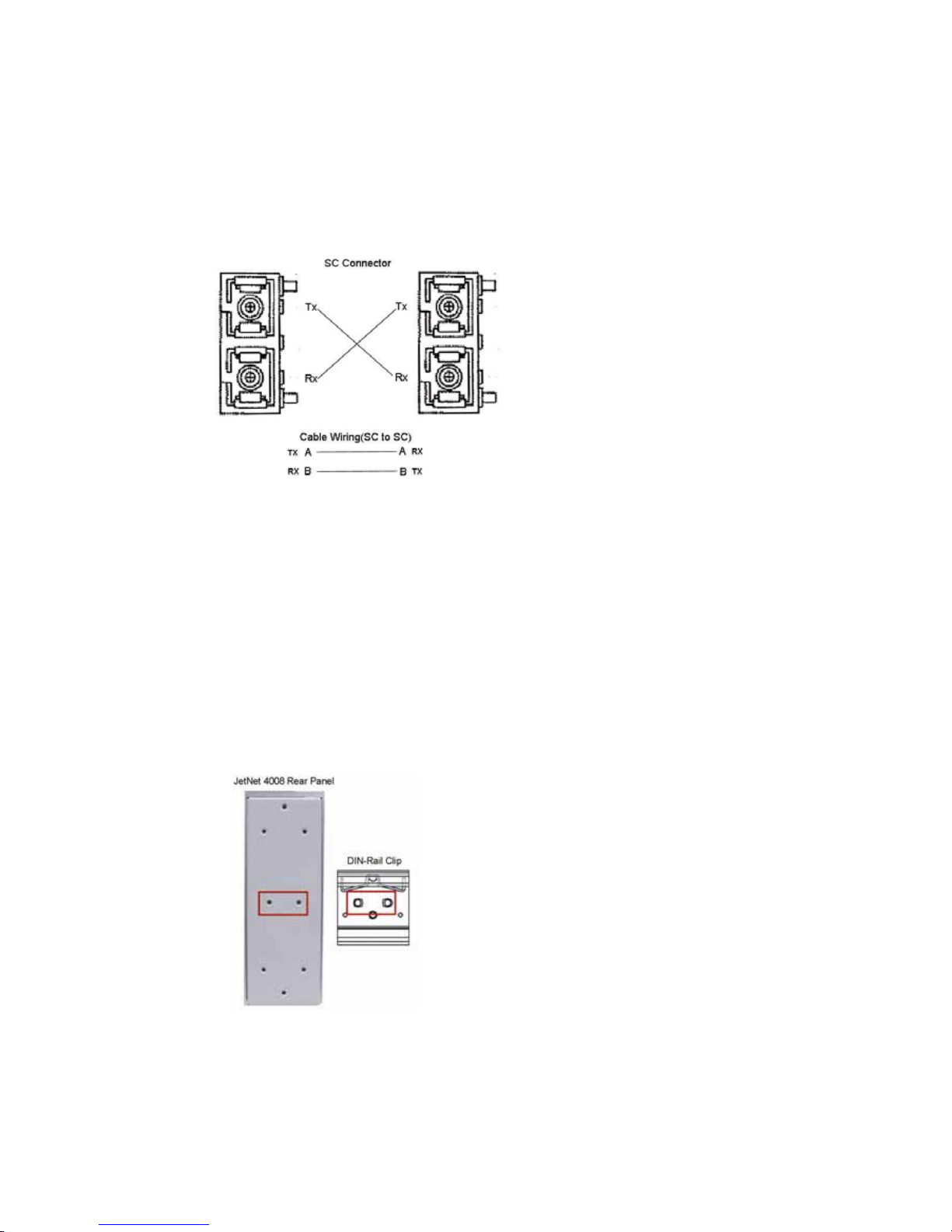
Wiring the Fiber Ports
To connect the fiber port on your JetNet 4005f or JetNet 4008f to another one located on another
JetNet, follow the figure below. Wrong connection will cause fiber ports not to work normally.
JetNet fiber models have two 100Base-FX ports with SC type connectors.
Fiber segment using single mode must use 9/125 or 10/125 um single-m ode fiber cables. For
single mode, the connection distance can be up to 30 km.
Fiber segment using multi mode must use 50 or 62.5/125 um multi-mode fiber cables. For single
mode, the connection distance can be up to 2 km.
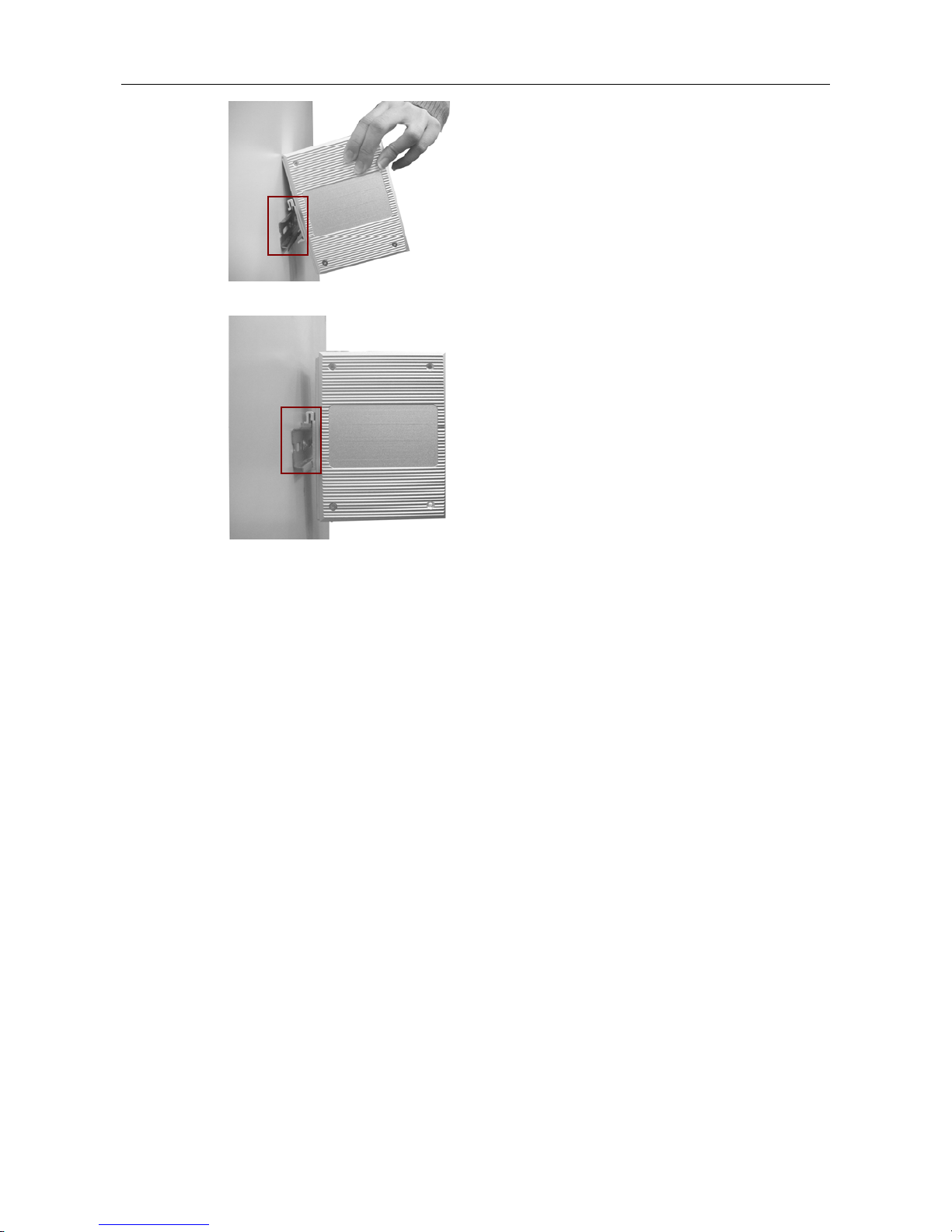
DIN-Rail Mounting Installation
The DIN-Rail clip is already attached to the JetNet 4000 Series products when packaged. If the
DIN-Rail clip is not screwed on the JetNet, follow the instructions and the figure below to attach
the DIN-Rail clip to the JetNet. Here we use JetNet 4008 as an example.
1. Use the screws to attach the DIN-Rail clip to the rear panel of the JetNet 4008.
2. To remove the DIN-Rail clip, reverse step 1.
Follow the steps below to mount the JetNet to the DIN-Rail track.
1. First, insert the upper end of the DIN-Rail clip into the back of the DIN-Rail track from its
upper side.
Hardware Installation
Korenix JetNet Series Industrial Web-Managed Ethernet Rail Switch User’s Manual
2-7
2. Lightly push the bottom of the DIN-Rail clip into the track.
3. Check if the DIN-Rail clip is tightly attached on the track.
4. To remove the JetNet from the track, reverse the steps above.
Wall-Mounting Installation
Follow the steps below to install the JetNet 4008f with the wall mounting plate.
1. To remove the DIN-Rail clip from the JetNet 4008f, loosen the screws from the DIN-Rail clip.
2. Place the wall mounting plate on the rear panel of the JetNet 400 8f.
3. Use the screws to tighten the wall mounting plate onto the JetNet 4008f.
4. Use the hook holes at the corners of the wall mounting plate to hang the JetNet 4008f onto
the wall.
5. To remove the wall mounting plate, reverse the steps above.
 Loading...