

Korenix JetCon 2301 V2 Series Quick Installation Manual

JetCon 2301 V2 Series
Industrial Fast Ethernet to Fiber Media Converter
Quick Installation Guide
www.korenix.com
V1.0
Introduction
JetCon 2301 V2 is a single port Fast Ethernet to Fiber media converter, supporting 4 types of
forwarding modes – Store and Forward, Modied Cut-through, Pure Converter and Converter
with auto-change modes. The JetCon 2301 V2 adopts rugged alum inum case with IP31
grade enclosure and 1.5KV Hi-Pot isolation protection to operate in harsh environments with
severe electromagnetic interference and -25~70°C (JetCon 2301 V2) or -40~75°C (JetCon
2301 V2-w). It features Link Los s F orwarding to for ward link status c hanges for alerting
remote or central management systems when a remote fault occurs. It also adopts one relay
output to alarm users if a port link fails or if the power fails. Alarms can be enabled/ disabled
by dip switch.
JetCon 2301 V2 has redundant power inputs with wide range DC10~60V through the 6-pin
removable terminal block. The ber port supports Single-mode or Multi-mode for providing
up to 30KM extended distance transmission.
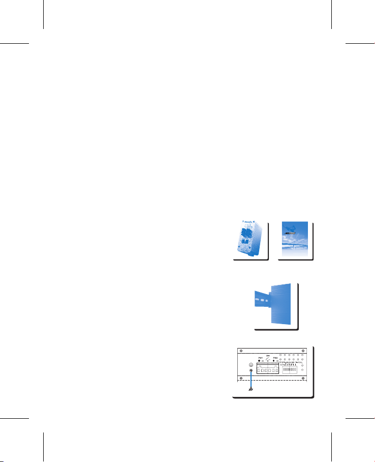
Package Checklist
Unpack the box and you will nd
4JetCon 2301 V2 Industrial Media Converter
4Quick Installation Guide
Mounting the Unit
Din-Rail mount: Mount the din-rail clip on the rear of
JetCon 2301 V2 on the DIN rail.
For information about the DIN Rail installation, please refer to
user’s manual.The user manual can be downloaded from the
Korenix Web site as below: http://www.korenix.com/downloads.htm
Grounding JetCon 2301 V2
There is one grounding screw on the bottom side of
JetCon 2301 V2 . Connect the frame grounding of JetCon
2301 V2 to the grounding surface to ensure safety and
prevent noise for communication interference.
Chassis connects
to the Earth Ground
JetNet 2301 V2 Series
Industrial Fast Ethernet to Fiber Rail Media Converter
Quick Installation Guide
www.korenix.com
V1.0
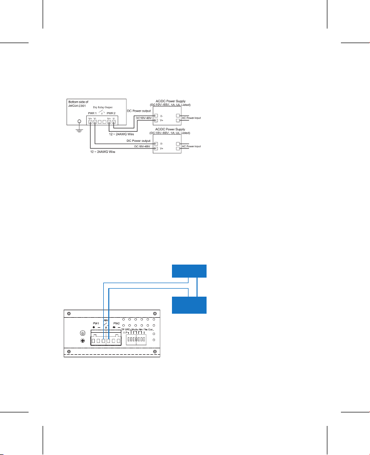
Wiring the Power Inputs
Wiring the Relay Output
1. Insert the positive and negative wires into the V+ and V- contact on the terminal block
connector.
The relay output contacts are in the middle of the terminal block connector as shown in
gure-3. By inserting the wires and by setting the DIP switch of the respective alarm function
to “ON”, relay output alarm will detect port or power fault, and form a short circuit. The alarm
relay output is “Normal Open”. See, Figure-3. For detailed information, please refer to
chapter 2-5 of the User’s Manual.
2. Tighten the wire-clamp screws to prevent the power wires from being loosened.
Note: The recommended working voltage is DC 24V (Input range: DC10~ 60 V)
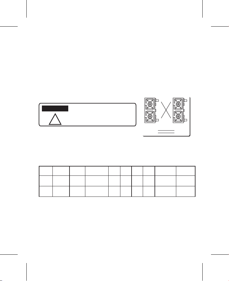
Accept 24AWG wire. JetCon 2301
V2 provides auto-polarity reverse
Note: The relay contact supports only 1A current,
DC 24V. It is not recommended to apply higher
voltage and current higher than this specication.
Maximum 1A Current / DC 24V
Alarm System
Extra Power
System
Connecting to Network
1. Connecting the Ethernet Port: Connect one end of an Ethernet cable into the UTP port of
JetCon 2301 V2, while the other end is connected to the attached networking device. UTP
port supports auto MDI/MDIX function. The LNK / ACT LED will turn on and start ashing to
indicate RJ-45 port links and the packets received and transmitted from RJ-45.
2. Connecting the Fiber Port: Connect the ber port of your JetCon 2301 V2 to another Fiber
Ethernet device, by following the gure below. Wrong connection or wrong ber cable type
will cause the ber port not working properly.
3. For different link distances, the JetCon 2301 V2 provides JetCon 2301 V2-m” for multi-
mode ber and “JetCon 2301 V2-s” for single-mode ber.
4. The table below illustrates ber transceiver specication.
xPwr(Min):Minimum Launch Power TxPwr(Max):Maximum Launch Power
RxPwr(Min):Maximum Receive Sensitivity RxPwr(Max):Minimum Receive Sensitivity
Link Budget=Minimum Launch Power –Maximum Receive Sensitivity
Note: To en sure y our b er con verter can t ransmit/receive data between the 2 nodes, the
attenuation of the optical ber cable should be smaller than the ber converter’s Link Budget.
This is a Class 1 Laser/LED product.
Don't stare into the Laser/LED Beam.
ATTENTION
!
RXTXRX
TX
RX A TX B
TX A RX B
Cable Wiring(SC to SC)
JetCon
2301 V2-m
JetCon
2301 V2-s
30km
2KM
Modul Fiber (um) ConnecterWavelength(um)
TXPwr
(Min)
TxPwr
(Max)
RxPwr
(Min)
RxPwr
(Max)
LinkBudg(dBm) Distance(km)
Single-Mode
8-10/125
SC 1310nm -15dBm-8dBm-34dBm 8dBm 19dBm
Multi-Mode
50~62.5/125
SC 1310nm -20dBm-14dBm-31dBm 0dBm11dBm
 Loading...