

Page 1
1
Korenix Technology Co., Ltd.
DR-4524 Quick Installation Guide
Follow the installation, wiring, and connection instructions specified below before using
switching power supplies.
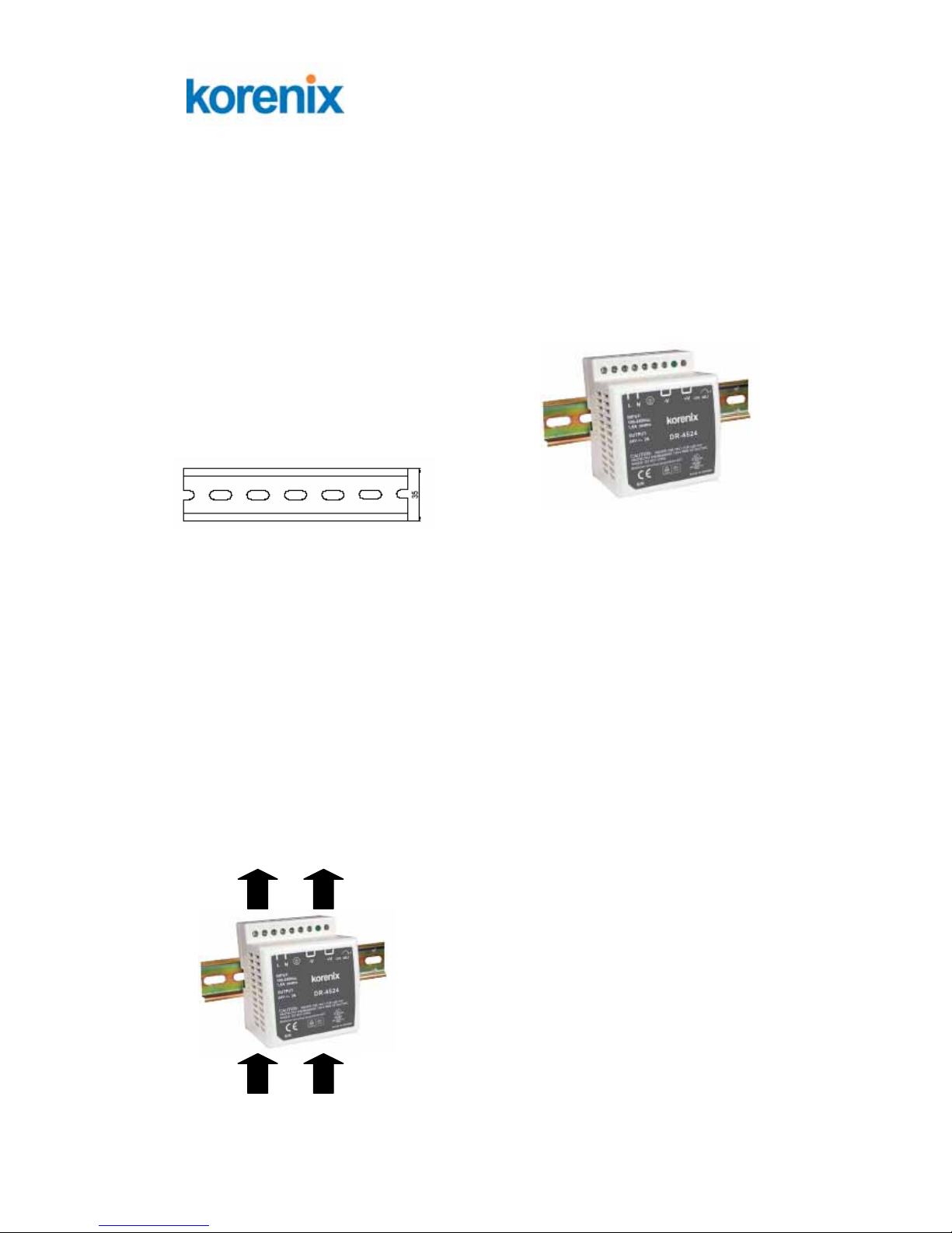
1. Installation
1.1 Mounting the power supply
a. Make sure the unit is properly ventilated.
b. Mounting the power supply into the DIN-rail track.
Admissible DIN-Rails: TS35/7.5 or TS35/15
b.1 Insert the upper end of the DIN-Rail clip into the back of the DIN-Rail track from its
upper side.
b.2 Pull down the plastic DIN-Rail lock and push the bottom of the DIN-Rail clip into the
track
b.3 Pull back plastic DIN-Rail lock and Check if the DIN-Rail clip is tightly attached on the
track
c. Make sure the unit has proper heat conduction. Do not cover the top and bottom wall
surface of the unit.
d. When you install two or more power supplies, leave enough space for cooling.
e. Forcing air over the unit will improve heat dissipation.
Air Outgoing
Incoming Air
Page 2
2
Korenix Technology Co., Ltd.
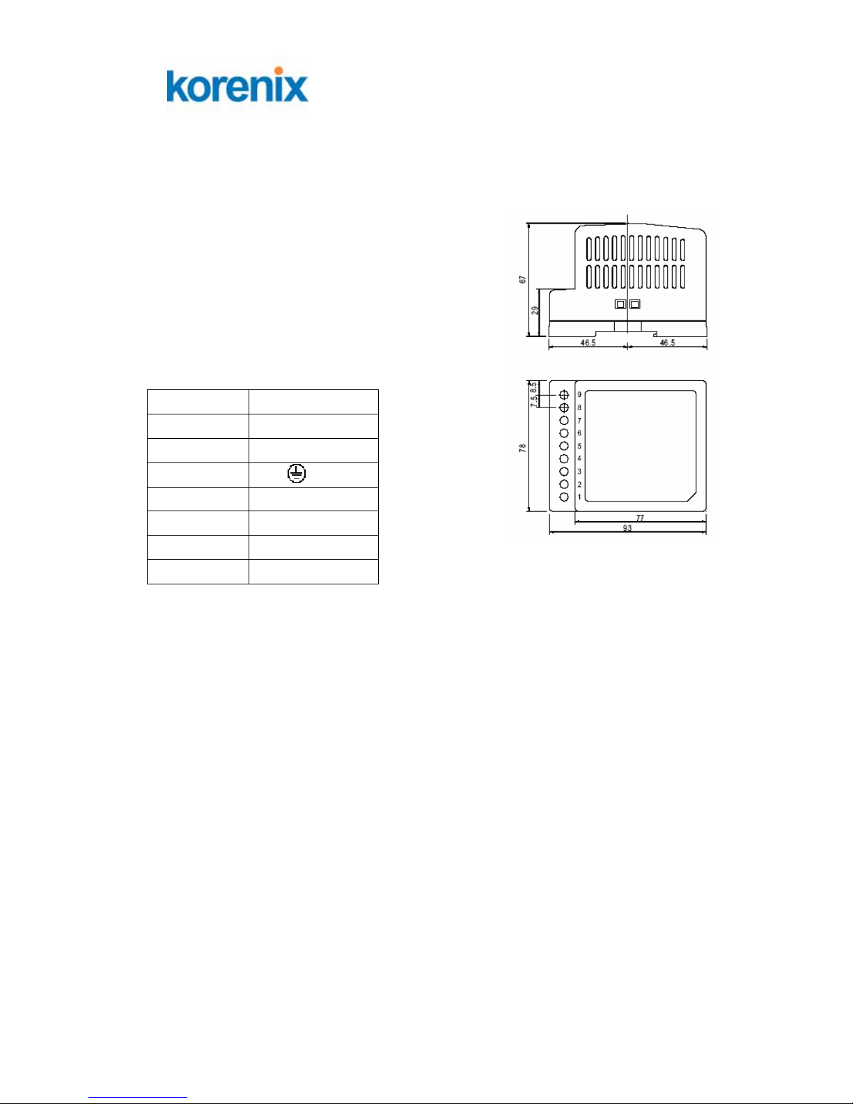
2. Wiring and Connections
2.1 AC Power Input and DC Output wiring
2.1.1 Connecting to DC Output: Insert the positive and
negative wires into the +V (Pin 6 or 7) and -V (Pin 4 or 5)
terminal contact, tighten terminal screws to prevent DC
Output wires from being loosened. Please be sure to
connect DC wires with correct polarity.
Terminal Pin No. Assignment
Pin No. Assignment
1 AC/ L
2 AC/ N
3
FG/
4, 5 DC OUTPUT -V
6, 7 DC OUTPUT +V
8 LED
9 +V ADJ.
2.1.2 Connecting to AC power Input: Insert AC power lines into terminal contact of Pin 1 &
Pin 2 of terminal contact, tighten terminal screws to prevent AC wires from being loosened.
2.1.3 Connecting to Frame Grounding (FG): Connect the frame grounding (Pin 3 of
Terminal contact) of switching power supply to the frame ground of the equipment with a short,
thick wire to ensure safety and prevent noise.
 Loading...