

Korenix 5010G Series, 4510 Series User Manual

1
Korenix 5010G / 4510 Series
Industrial Managed Ethernet Switch
User Manual
Ver. 2.11, Apr-2013
Firmware v2.7
Hardware v2.3
www.korenix.com

2
Korenix JetNet 5010G/ 4510 Series
Industrial Managed Ethernet Switch
User’s Manual
Copyright Notice
Copyright 2007-2013 Korenix Technology Co., Ltd.
All rights reserved.
Reproduction in any form or by any means without permission is prohibited.

3
Federal Communications Commission (FCC) Statement
This equipment has been tested and found to comply with the limits for a Class
A digital device, pursuant to Part 15 of the FCC Rules. These limits are
designed to provide reasonable protection against harmful interference when
the equipment is operated in a commercial environment. This equipment
generates, uses, and can radiate radio frequency energy and, if not installed
and used in accordance with the instruction manual, may cause harmful
interference to radio communications. Operation of this equipment in a
residential area is likely to cause harmful interference in which case the user
will be required to correct the interference at his expense.
The user is cautioned that changes and modifications made to the equipment
without approval of the manufacturer could void the user's authority to operate
this equipment.

Index
1 Introduction ........................................................................................................................... 1
1.1 Overview .................................................................................................................... 1
1.2 Major Features ........................................................................................................... 1
1.3 Package List .............................................................................................................. 2
2 Hardware Installation ........................................................................................................... 4
2.1 Hardware Introduction ............................................................................................... 5
2.2 Wiring Power Inputs .................................................................................................. 7
2.3 Wiring Digital Input .................................................................................................... 8
2.4 Wiring Digital Output.................................................................................................. 8
2.5 Wiring Earth Ground .................................................................................................. 8
2.6 Wiring Fast Ethernet Ports ........................................................................................ 9
2.7 Wiring Combo Ports ................................................................................................10
2.8 Wiring RS-232 Console Cable ................................................................................10
2.9 DIN-Rail Mounting Installation ................................................................................ 11
2.10 Wall-Mounting Installation .......................................................................................13
3 Preparation for Management ............................................................................................ 14
3.1 Preparation for Serial Console ................................................................................14
3.2 Preparation for Web Interface .................................................................................15
3.3 Preparation for Telnet Console ...............................................................................17
4 Feature Configuration ....................................................................................................... 20
4.1 Command Line Interface Introduction ....................................................................21
4.2 Basic Setting ............................................................................................................26
4.3 Port Configuration ....................................................................................................42
4.4 Network Redundancy ..............................................................................................50
4.5 VLAN ........................................................................................................................69
4.6 Private VLAN ...........................................................................................................79
4.7 Traffic Prioritization ..................................................................................................85
4.8 Multicast Filtering .....................................................................................................90
4.9 SNMP .......................................................................................................................94
4.10 Security ....................................................................................................................97
4.11 Warning ..................................................................................................................103
4.12 Monitor and Diag ................................................................................................... 112
4.12 Device Front Panel ................................................................................................ 118
4.13 Save to Flash ......................................................................................................... 119
4.14 Logout ....................................................................................................................120
5. Appendix ................................................................................................................................ 121
5.1 Pin Assignment of the RS-232 Console Cable.....................................................121
5.2 Korenix SFP family ................................................................................................122
5.3 Korenix Private MIB ...............................................................................................125
5.4 ModBus TCP /IP ....................................................................................................126
5.5 Revision History .....................................................................................................137
5.6 About Korenix ........................................................................................................139

1
1 Introduction
Welcome to Korenix 7 10/100TX plus 3 10/100/1000TX/100FX/1000FX Industrial
Managed Ethernet Switch User Manual. This manual covers several Managed Ethernet
Switch models for different Ethernet port combination. The following topics are covered
in this chapter
1.1 Overview
1.2 Major Features
1.3 Package Checklist
1.1 Overview
Industrial 10-port Managed Ethernet Switches, have 7 10/100Base-TX ports and 3 combo ports,
respectively 10/100/1000 RJ-45 / 100FX / Gigabit SX/LX, or 10/100 RJ-45 /100FX for diferent
modesl. Those Switches is especially designed to operate under harsh environmental conditions.
The switches provide solid foundation for a highly fault-tolerant and easily-managed network. The
Managed 10-port Switch can be remotely configured by Telnet, Web browser, JetView and
managed by Simple Network Management Protocol (SNMP) and Remote Monitoring (RMON).
You can also connect the attached RS232 console cable to manage the switch by Command Line
Interface (CLI). CLI commands are Cisco-Like commands, your engineers who are familiar with
Cisco products don’t need to learn new rules for CLI commands.
Security is enhanced with advanced features such as 802.1Q VLAN and Port/IP security.
Performance is optimized by QoS and IGMP Snooping/Query. Korenix 3nd generation Ring
technology, Multiple Super Ring, enables superb self-healing capability for network failure. The
fastest failover time is enhanced from 300ms to 5ms for 10/100TX RJ-45 ports, and 30ms for
100FX and Gigabit Fiber. This is Korenix patented ring technology, which is registered in most
countries. For interoperability with your existed network, the 10-port Managed Switch series also
come with an advanced redundant network solution, Ring Coupling and Rapid Dual Homing
technology. With Ring Coupling and Rapid Dual Homing technology, Ethernet Ring can be
extended more easily. No matter with Korenix switch or other managed switches.
The IP31-design aluminum case further strengthens the Switch’s withstand ability in harsh
industrial environment. The event warning is notified to the network administrator via e-mail,
system log, or to field engineers by relay output. The Industrial Managed Ethernet Switch has also
passed CE/ FCC/ UL safety certifications to help ensure safe and reliable data transmission for
industrial applications. The 10-Port Managed Ethernet Switch Series will be your best option for
highly-managed industrial network.
1.2 Major Features
Korenix 10-port Manaed Ethernet Switch Series products have the following features:
SFP ports support 100/1000 Fiber with Digital Diagnostic Monitoring (DDM) to
monitor long distance fiber quality.

2
Multiple Super Ring (recovery time <5ms), Rapid Dual Homing, Multiple Ring, and
MSTP/RSTP
VLAN, Private VLAN, QinQ, GVRP, QoS, IGMP Snooping V1/V2/V3, Rate Control,
Port Trunking, LACP, Online Multi-Port Mirroring
32Gbps Non-Blocking, switch backplane 8K MAC address table
Supports LLDP and JetViewPro i2NMS software for auto topology visualization and
efficient group management
Supports console CLI , Web, SNMP V1/V2c/V3, RMON, HTTPS, SSH for remote
management
Advanced security feature supports IP Security, Port Security, advanced
SSHL/SSL authenciation key configuration, Telnet/Http service control
DHCP Server with advanced function –DHCP option 82 with Relay circuit, DHCP
server by port based, IP and MAC Binding, 802.1x network access control.
Event Notification by E-mail, SNMP trap, Syslog, Digital Input and Relay Output
Supports Modbus TCP/IP client for Factory Automation
Supports Multiple Language for Web User Interface
10.5~60Vdc (v2.3 Hardware)
IP31 rugged aluminum case
Operating temperature -25~70°C for 7+3G/ 7+3 100 Switch, -40~75°C for wide
temperature mode 7+3G/ 7+3 100 Switch; For the UL 60950-1, the high
temperature only support 60°C for all models
Note: The detail spec is listed in Appendix 5.1.
The following table listed the nick name used in this user manual for Korenix model
mapping.
Model
Description
Managed/ Temperature
JetNet 5010G
7 10/100TX, plus 3 10/100/1000TX, SFP 100FX/1000X Combo. (7+3G)
Telnet, SNMP, Http (Web),-25~70°C
JetNet 4510
7 10/100TX, plus 3 10/100TX, SFP 100FX Combo. (7+3 100)
Telnet, SNMP, Http (Web) ,-25~70°C
JetNet 5010G-w
7 10/100TX, plus 3 10/100/1000TX, SFP 100FX/1000X Combo. (7+3G)
Telnet, SNMP, Http (Web) ,-40~75°C
JetNet 4510-w
7 10/100TX, plus 3 10/100TX, SFP 100FX Combo. (7+3 100)
Telnet, SNMP, Http (Web) ,-40~75°C
1.3 Package List
The product is shipped with following items:
One industrial Managed Ethernet switch
One DIN-Rail clip (attached to the switch)
One wall mounting plate and 4 screws (M3 in 6 mm length)
One RS-232 DB-9 to RJ-45 console cable
Documentation and Software CD

3
Quick Installation Guide
If any of the above items are missing or damaged, please contact your local sales
representative.

4
2 Hardware Installation
This chapter includes hardware introduction, installation and configuration information.
Following topics are covered in this chapter:
2.1 Hardware Introduction
Dimension
Panel Layout
Bottom View
2.2 Wiring Power Inputs
2.3 Wiring Digital Input
2.4 Wiring Relay Output
2.5 Wiring Ethernet Ports
2.6 Wiring Combo Ports
2.7 Wiring RS-232 console cable
2.8 DIN-Rail Mounting Installation
2.9 Wall-Mounting Installation
5
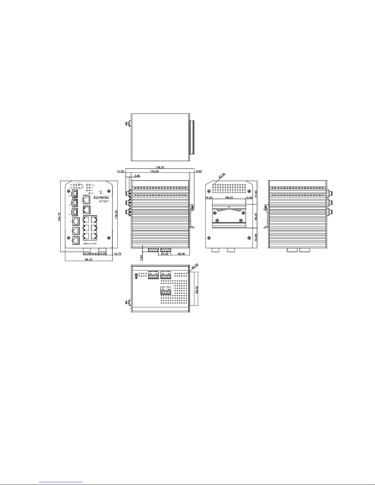
2.1 Hardware Introduction
Dimension
Industrial 7+3G /7+3 100 Managed Switch witch dimension (W x H x D) is 96mm x
137mm x 119mm

6
Panel Layout
The front panel includes 10/100Mbps Fast Ethernet ports, Gigabit Ethernet ports, SFP
slot, RS232 console port, System / Combo Port LED and Reset button.
Bottom View
The bottom view of the Industrial 7+3 Gigabit Managed Switch consists of three terminal
block connectors with two DC power inputs, two Digital Inputs, 2 Relay Outputs and 1
Earth Ground.
Note: The unit intended to use vertical direction, with DIN-rail or
wall-mount only.
7
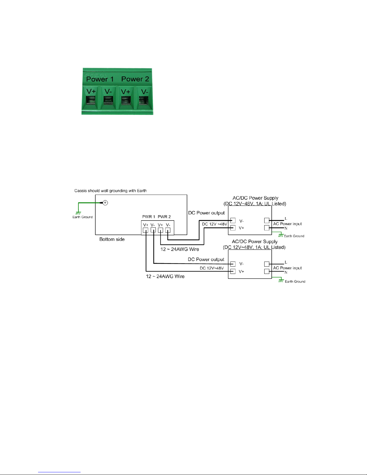
2.2 Wiring Power Inputs
Follow below steps to wire the Switch’s redundant DC power inputs.
1. Insert positive and negative wires into V+ and V- contacts respectively of the
terminal block connector
2. Tighten the wire-clamp screws to prevent DC wires from being loosened.
3. Power 1 and Power 2 support power redundancy and polarity reverse protection
functions.
4. Positive and negative power system inputs are both accepted, but Power 1 and
Power 2 must apply the same mode.
Note 1: It is a good practice to turn off input and load power, and to unplug power terminal
block before making wire connections. Otherwise, your screwdriver blade can
inadvertently short your terminal connections to the grounded enclosure.
Note 2: The range of the suitable electric wire is from 12 to 24 AWG.
Note 3: If the 2 power inputs are connected, the Switch will be powered from the highest
connected voltage. The unit will alarm for loss of power, either PWR1 or PWR2.
Note 4: To use the UL Listed LPS power supply with output Rating 12-48 Vdc or
10.5~60Vdc for 2.3 hardware version, minimum 1 A.
8
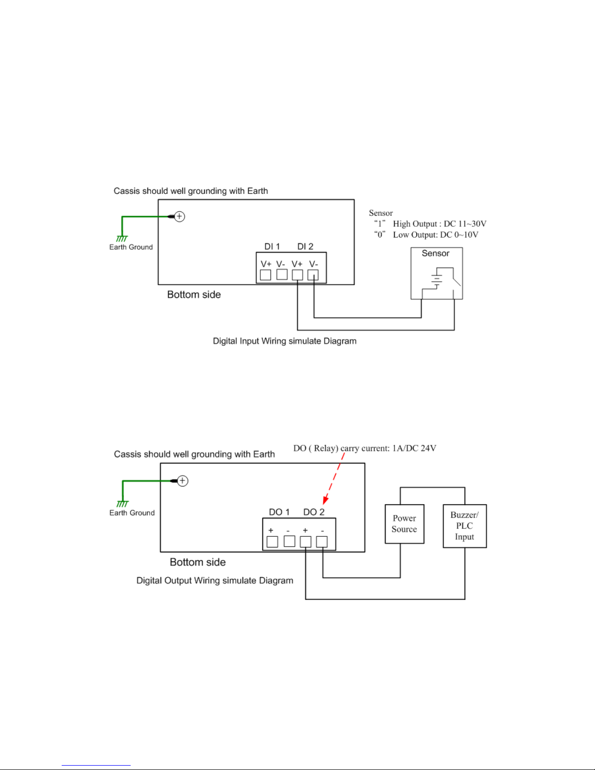
2.3 Wiring Digital Input
The Switch provides 2 digital inputs. It allows users to connect the termination units’ digital
output and manage/monitor the status of the connected unit. The Digital Input pin can be
pulled high or low; thus the connected equipments can actively drive these pins high or
low. The embedded software UI allows you to read and set the value to the connected
device.
The power input voltage of logic low is DC 0~10V. Logic high is DC 11~30V.
Wire the digital input just like wiring the power input introduced in chapter 2.2.
2.4 Wiring Digital Output
The Switch provides 2 digital outputs, also known as Relay Output. The relay contacts are
energized (open) for normal operation and will close for fault conditions. The fault
conditions include power failure, Ethernet port link break or other pre-defined events
which can be configured in Switch’s Web User Interface.
Wiring digital output is exactly the same as wiring power input introduced in chapter 2.2.
2.5 Wiring Earth Ground
To ensure the system will not be damaged by noise or any electrical shock, we suggest
you to make exact connection between the Switch and Earth Grounding System.
On the bottom side of the Switch, there is one earth ground screw. Loosen the earth
ground screw by screw drive; then tighten the screw after earth ground wire is connected.

9
2.6 Wiring Fast Ethernet Ports
The Switch includes 7 RJ-45 Fast Ethernet ports. The fast Ethernet ports support
10Base-T and 100Base-TX, full or half duplex modes. All the fast Ethernet ports will
auto-detect the signal from connected devices to negotiate the link speed and duplex
mode. Auto MDI/MDIX allows users to connect another switch, hub or workstation without
changing straight through or crossover cables.
Note that crossover cables simply cross-connect the transmit lines at each end to the
received lines at the opposite end.
Straight-through Cabling Schematic
Cross-over Cabling Schematic
Note that Ethernet cables use pins 1, 2, 3, and 6 of an 8-pin RJ-45 connector. The signals
of these pins are converted by the automatic MDI-X function, as shown in the table below:
Pin MDI-X
Signals
MDI Signals
1
RD+
TD+
2
RD-
TD-
3
TD+
RD+
6
TD-
RD-
Connect one side of an Ethernet cable into any switch port and connect the other side to
your attached device. The LNK LED will light up when the cable is correctly connected.
Refer to the LED Indicators section for descriptions of each LED indicator. Always make
sure that the cables between the switches and attached devices (e.g. switch, hub, or

10
workstation) are less than 100 meters (328 feet).
The wiring cable types are as below.
10Base-T: 2-pair UTP/STP Cat. 3, 4, 5 cable, EIA/TIA-568B 100-ohm (100m)
100 Base-TX: 2-pair UTP/STP Cat. 5 cable, EIA/TIA-568B 100-ohm (100m)
1000 Base-T: 4-pair UTP/STP Cat. 5 cable, EIA/TIA-568B 100-ohm (100m)
2.7 Wiring Combo Ports
The Switch, 7+3G includes 3 RJ-45 Gigabit Ethernet and combo with Gigabit SFP ports.
The speed of the Gigabit Ethernet RJ-45 port supports 10Base-T, 100Base-TX,
1000Base-T, and the SFP ports are combo design with RJ-45 ports. The SFP ports
support Small Form Factor GBIC Transceiver (MINI GBIC) for 100Mbps and 1000Mbps.
For the 7+3 100 Switch, the 3 100 RJ-45 Ethernet are combo design with 100Mbps SFP
ports, which menas the SFP ports only support 100Mbps Small Form Factor GBIC
Transceiver (MINI GBIC).
It is recommended using the certificated SFP Transceiver. The certificated SFP
transceiver includes 100Base-FX single/multi mode, 1000Base-SX/LX single/multi mode
ranger from 550m to 80KM.
To keep best performance, the SFP fiber ports will not support Fiber Link First
function anymore after firmware version v2.4b, since the SFP fiber transceiver
vendor have applied energy saving technology and changed the circuit design that
will cause SFP transceiver can’t offer energy of fiber link signature to switches the
connection from RJ-45 to fiber, even the SFP fiber transceiver already link up.
To fix that issue, new v2.4b firmware have applied plug-in and switch to fiber mode
feature. It forced the connection change from RJ-45 to SFP immediately, once the
SFP transceiver inserted and detected by CPU.
Note: The Ethernet Switch has to use UL recognized fiber transceiver with Class 1
Laser/LED Diode.
Note: It is recommended don’t plug-in SFP fiber transceiver and link up RJ-45 port
at same time, it might cause the connection does not work properly.
2.8 Wiring RS-232 Console Cable
It attachesd one RS-232 DB-9 to RJ-45 cable in the box. Connect the DB-9 connector to
the COM port of your PC, open Terminal tool and set up serial settings to 9600, N,8,1.
(Baud Rate: 9600 / Parity: None / Data Bit: 8 / Stop Bit: 1) Then you can access CLI
interface by console able.
Note: If you lost the cable, please contact with your sales or follow the pin assignment to
buy a new one. The Pin assignment spec is listed in the appendix.
11
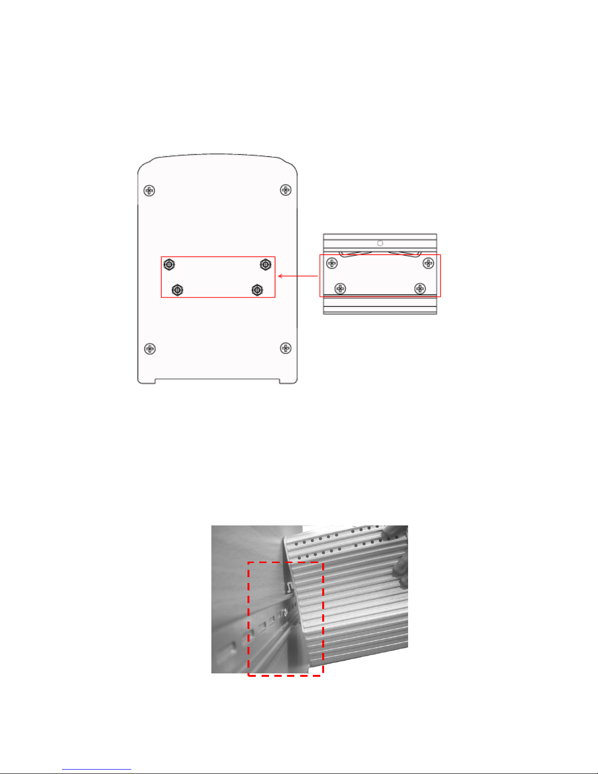
2.9 DIN-Rail Mounting Installation
The DIN-Rail clip is already attached to the Switch when packaged. If the DIN-Rail clip is
not screwed on the Switch, follow the instructions and the figure below to attach DIN-Rail
clip to the Switch.
Follow the steps below to mount the Ethernet Switch to the DIN-Rail track:
1. First, insert the upper end of DIN-Rail clip into the back of DIN-Rail track from its
upper side.
2. Lightly push the bottom of DIN-Rail clip into the track.
1. Use the screws to attach DIN-Rail clip to the real panel of
Switch.
2. To remove DIN-Rail clip, reverse step 1.
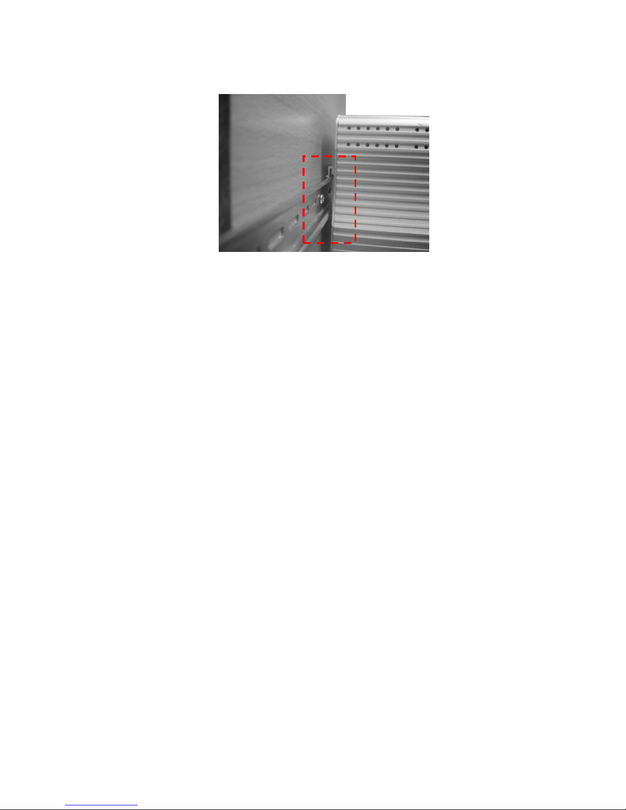
12
3. Check if DIN-Rail clip is tightly attached on the track.
4. To remove it from the track, reverse the steps above.
Notes: The DIN Rail should compliance with DIN EN50022 standard.
Using wrong DIN rail may cause system install unsafe.

13
2.10 Wall-Mounting Installation
Follow the steps below to install the Switch with the wall mounting plate.
1. To remove DIN-Rail clip from the Switch, loosen the screws from DIN-Rail clip.
2. Place the wall mounting plate on the rear panel of Switch
3. Use the screws to tighten the wall mounting plate onto the Switch.
4. Use the hook holes at the corners of the wall mounting plate to hang the Switch onto
the wall.
5. To remove the wall mounting plate, reverse the steps above.
Note: To avoid damage the internal circuit, be sure use the screw included in the
package to screw and tight the wall-mount kit onto the rear side of the JetNet switch.
The specification of screw is M3 in 6 mm length.

14
3 Preparation for Management
The Industrial Managed Switch provides both in-band and out-band configuration
methods. You can configure the switch via RS232 console cable if you don’t attach your
admin PC to your network, or if you lose network connection to your Switch. This is
so-called out-band management. It wouldn’t be affected by network performance.
The in-band management means you can remotely manage the switch via the network.
You can choose Telnet or Web-based management. You just need to know the device’s
IP address and you can remotely connect to its embedded HTTP web pages or Telnet
console.
Following topics are covered in this chapter:
3.1 Preparation for Serial Console
3.2 Preparation for Web Interface
3.3 Preparation for Telnet console
Note: It is recommended management session don’t exceed 2 accounts for Web and
Telnet management. Once the session exceeds 3 accounts, the system kernel may show
some information in the local / telnet interface.
3.1 Preparation for Serial Console
In the package, Korenix attached one RS-232 DB-9 to RJ-45 console cable. Please
attach RS-232 DB-9 connector to your PC COM port, connect RJ-45 to the Console port
of the Switch. If you lose the cable, please follow the console cable PIN assignment to
find one. (Refer to the appendix).
1. Go to Start -> Program -> Accessories -> Communication -> Hyper Terminal
2. Give a name to the new console connection.
3. Choose the COM name
4. Select correct serial settings. The serial settings of Switch are as below:
Baud Rate: 9600 / Parity: None / Data Bit: 8 / Stop Bit: 1
5. After connected, you can see Switch login request.
6. Login the switch. The default username is “admin”, password, “admin”.
Booting...
Sun Jan 1 00:00:00 UTC 2006
Switch login: admin
Password:
JetNet5010G (version 2.1.5-20080414-11:04:13).
Copyright 2006-2008 Korenix Technology Co., Ltd.
Switch>
15
3.2 Preparation for Web Interface
The Switch provides HTTP Web Interface and Secured HTTPS Web Interface for web
management.
3.2.1 Web Interface
Korenix web management page is developed by JAVA. It allows you to use a standard
web-browser such as Microsoft Internet Explorer, or Mozila, to configure and interrogate
the switch from anywhere on the network.
Before you attempt to use the embedded web interface to manage switch operation,
verify that your Industrial Ethernet Switch is properly installed on your network and that
every PC on this network can access the switch via the web browser.
1. Verify that your network interface card (NIC) is operational, and that your operating
system supports TCP/IP protocol.
2. Wire DC power to the switch and connect your switch to your computer.
3. Make sure that the switch default IP address is 192.168.10.1.
4. Change your computer IP address to 192.168.10.2 or other IP address which is
located in the 192.168.10.x (Network Mask: 255.255.255.0) subnet.
5. Switch to DOS command mode and ping 192.168.10.1 to verify a normal response
time.
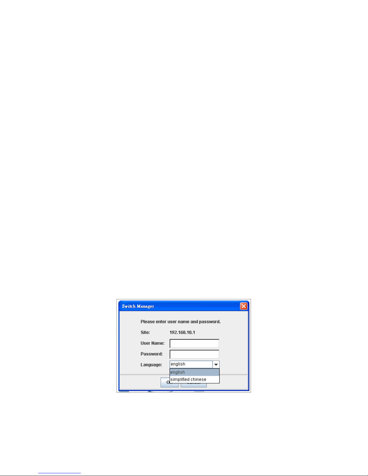
Launch the web browser and Login.
6. Launch the web browser (Internet Explorer or Mozila Firefox) on the PC.
7. Type http://192.168.10.1 (or the IP address of the switch). And then press Enter.
8. The login screen will appear next.
9. Key in user name and the password. Default user name and password are both
admin.
10. Select Language type, this feature is available from firmware v2.5 that supports
English and Simplified Chinese.
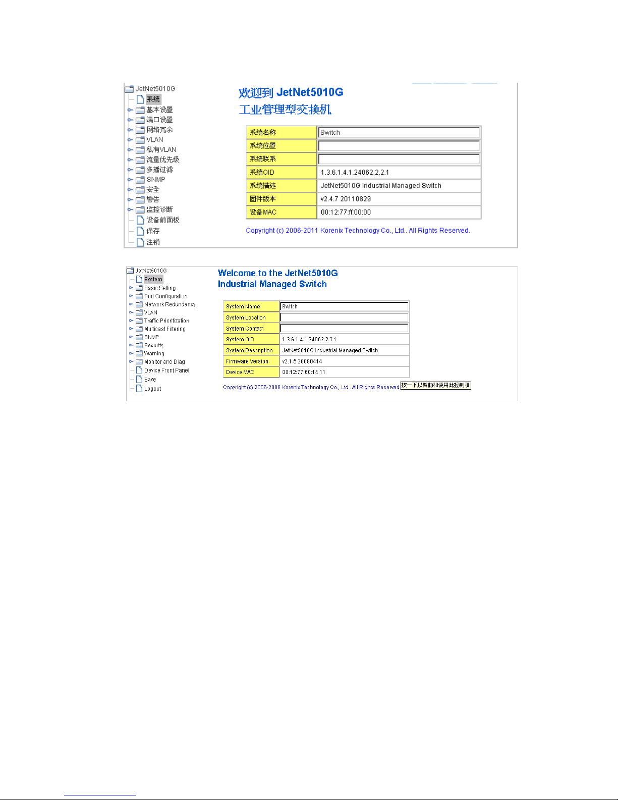
Click on Enter or OK. Welcome page of the web-based management interface will then
appear.
16
Once you enter the web-based management interface, you can freely change the
JetNet’s IP address to fit your network environment.
Note 1: IE 5.0 or later versions do not allow Java applets to open sockets by default.
Users have to directly modify the browser settings to selectively enable Java applets to
use network ports.
Note 2: The Web UI connection session of the Switch will be logged out automatically if
you don’t give any input after 30 seconds. After logged out, you should re-login and key
in correct user name and password again.
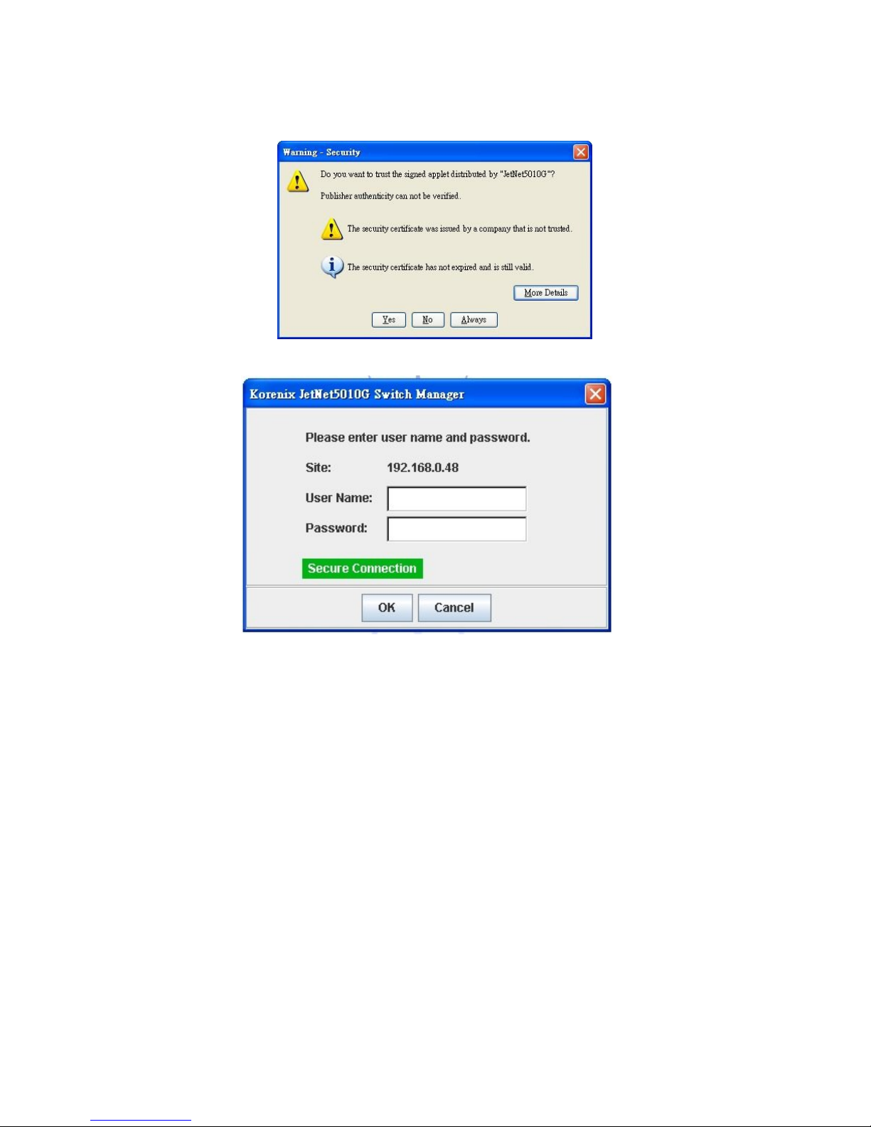
3.2.2 Secured Web Interface
Korenix web management page also provides secured management HTTPS login. All
the configuration commands will be secured and will be hard for the hackers to sniff the
login password and configuration commands.
Launch the web browser and Login.
1. Launch the web browser (Internet Explorer or Mozila Firefox) on the PC.
2. Type https://192.168.10.1 (or the IP address of the switch). And then press Enter.
English language
Simplified Chinese
Language
17
3. The popup screen will appear and request you to trust the secured HTTPS
connection distributed by the Switch first. Press “Yes” to trust it.
4. The login screen will appear next.
5. Key in the user name and the password. The default user name and password is
admin.
6. Click on Enter or OK. Welcome page of the web-based management interface will
then appear.
7. Once you enter the web-based management interface, all the commands you see
are the same as what you see by HTTP login.
3.3 Preparation for Telnet Console
3.3.1 Telnet
The Switch supports Telnet console. You can connect to the switch by Telnet and the
command lines are the same as what you see by RS232 console port. Below are the
steps to open Telnet connection to the switch.
1. Go to Start -> Run -> cmd. And then press Enter
2. Type the Telnet 192.168.10.1 (or the IP address of the switch). And then press
Enter

18
3.3.2 SSH (Secure Shell)
The Switch also support SSH console. You can remotely connect to the switch by
command line interface. The SSH connection can secure all the configuration
commands you sent to the switch.
SSH is a client/server architecture while the Switch is the SSH server. When you want to
make SSH connection with the switch, you should download the SSH client tool first.
SSH Client
There are many free, sharewares, trials or charged SSH clients you can find on the
internet. Fox example, PuTTY is a free and popular Telnet/SSH client. We’ll use this
tool to demonstrate how to login JetNet by SSH. Note: PuTTY is copyright 1997-2006
Simon Tatham.
Download PuTTY: http://www.chiark.greenend.org.uk/~sgtatham/putty/download.html
The copyright of PuTTY
1. Open SSH Client/PuTTY
In the Session configuration, enter the Host Name (IP Address of your Switch) and
Port number (default = 22). Choose the “SSH” protocol. Then click on “Open” to start
the SSH session console.
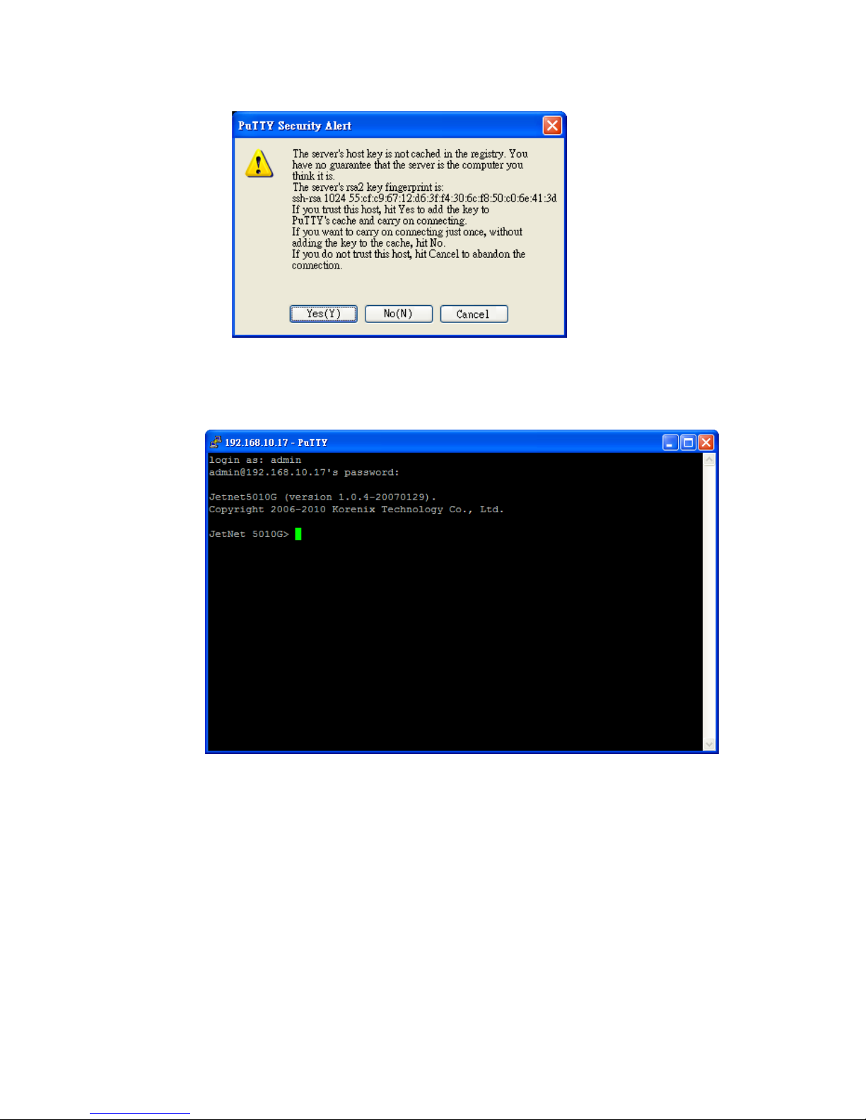
2. After click on Open, then you can see the cipher information in the popup screen.
Press Yes to accept the Security Alert.
19
3. After few seconds, the SSH connection is opened. You can see the login screen as
the below figure.
4. Type the Login Name and its Password. The default Login Name and Password are
admin / admin.
5. All the commands you see in SSH are the same as the CLI commands you see via
RS232 console. The next chapter will introduce in detail how to use command line to
configure the switch.

20
4 Feature Configuration
This chapter explains how to configure Switch’s software features. There are four ways to
access the switch: Serial console, Telnet, Web browser and SNMP.
The Industrial Managed Switch provides both in-band and out-band configuration methods.
You can configure the switch via RS232 console cable if you don’t attach your admin PC to
your network, or if you lose the network connection to your Switch. This is so-called
out-band management. It wouldn’t be affected by the network performance.
The in-band management means you can remotely manage the switch via the network.
You can choose Telnet or Web-based management. You just need to know the device’s IP
address. Then you can remotely connect to its embedded HTML web pages or Telnet
console.
Korenix web management page is developed by JAVA. It allows you to use a standard
web-browser such as Microsoft Internet Explorer, or Mozila, to configure and interrogate
the switch from anywhere on the network.
Note: IE 5.0 or later versions do not allow Java applets to open sockets by default. Users
have to directly modify the browser settings to selectively enable Java applets to use
network ports.
Following topics are covered in this chapter:
4.1 Command Line Interface (CLI) Introduction
4.2 Basic Setting
4.3 Port Configuration
4.4 Network Redundancy
4.5 VLAN
4.6 Traffic Prioritization
4.7 Multicast Filtering
4.8 SNMP
4.9 Security
4.10 Warning
4.11 Monitor and Diag
4.12 Device Front Panel
4.13 Save
4.14 Logout

21
4.1 Command Line Interface Introduction
The Command Line Interface (CLI) is the user interface to the switch’s embedded software
system. You can view the system information, show the status, configure the switch and
receive a response back from the system by keying in a command.
There are some different command modes. Each command mode has its own access
ability, available command lines and uses different command lines to enter and exit. These
modes are User EXEC, Privileged EXEC, Global Configuration, (Port/VLAN) Interface
Configuration modes.
User EXEC mode: As long as you login the switch by CLI. You are in the User EXEC mode.
You can ping, telnet remote device, and show some basic information.
Type enable to enter next mode, exit to logout. ? to see the command list
Privileged EXEC mode: Press enable in the User EXEC mode, then you can enter the
Privileged EXEC mode. In this mode, the system allows you to view current configuration,
reset default, reload switch, show system information, save configuration…and enter the
global configuration mode.
Type configure terminal to enter next mode, exit to leave. ? to see the command list
Switch>
enable Turn on privileged mode command
exit Exit current mode and down to previous mode
list Print command list
ping Send echo messages
quit Exit current mode and down to previous mode
show Show running system information
telnet Open a telnet connection
traceroute Trace route to destination
Switch#
archive manage archive files
clear Reset functions
clock Configure time-of-day clock
configure Configuration from vty interface
copy Copy from one file to another
debug Debugging functions (see also 'undebug')
disable Turn off privileged mode command
end End current mode and change to enable mode
exit Exit current mode and down to previous mode
list Print command list
more Display the contents of a file
no Negate a command or set its defaults
ping Send echo messages
quit Exit current mode and down to previous mode
reboot Reboot system
reload copy a default-config file to replace the current one
show Show running system information
telnet Open a telnet connection
terminal Set terminal line parameters
traceroute Trace route to destination
write Write running configuration to memory, network, or terminal

22
Global Configuration Mode: Press configure terminal in privileged EXEC mode. You
can then enter global configuration mode. In global configuration mode, you can configure
all the features that the system provides you.
Type interface IFNAME/VLAN to enter interface configuration mode, exit to leave. ? to
see the command list.
Available command lists of global configuration mode.
(Port) Interface Configuration: Press interface IFNAME in global configuration mode.
You can then enter interface configuration mode. In this mode, you can configure port
settings.
The port interface’s code name for fast Ethernet port 1 is fa1, and fast Ethernet 7 is fa7,
gigabit Ethernet port 8 is gi8, the gigabit Ethernet port 10 is gi10. Type in the interface‘s
code name accordingly when you want to enter certain interface configuration mode.
Type ” exit” to leave.
Type “?” to see the command list
Switch# configure terminal
Switch(config)#
administrator Administrator account setting
arp Set a static ARP entry
auth Authentication
clock Configure time-of-day clock
default Set a command to its defaults
dot1x IEEE 802.1x standard access security control
end End current mode and change to enable mode
ethertype Ethertype
exit Exit current mode and down to previous mode
gvrp GARP VLAN Registration Protocol
hostname Set system's network name
interface Select an interface to configure
ip IP information
ipv6 IP information
jetview JetView Protocol
lacp Link Aggregation Control Protocol
list Print command list
lldp Link Layer Discovery Protocol
log Logging control
loop-protect Ethernet loop protection
mac-address-table mac address table
mirror Port mirroring
modbus Modbus TCP Slave
multiple-super-ring Configure Multiple Super Ring
nameserver DNS Server
no Negate a command or set its defaults
ntp Configure NTP
qos Quality of Service (QoS)
relay relay output type information
router Enable a routing process
service System service
sfp Small form-factor pluggable
smtp-server SMTP server configuration
snmp-server the SNMP server
spanning-tree the spanning tree algorithm
trunk Trunk group configuration
vlan Virtual LAN
warning-event Warning event selection
write-config Specify config files to write to

23
Available command lists of the global configuration mode.
(VLAN) Interface Configuration: Press interface VLAN VLAN-ID in global configuration
mode. You can then enter VLAN interface configuration mode. In this mode, you can
configure the settings for the specific VLAN.
The VLAN interface name of VLAN 1 is VLAN 1, VLAN 2 is VLAN 2…
Type exit to leave the mode. Type ? to see the available command list.
The command lists of the VLAN interface configuration mode.
Switch(config)# interface vlan 1
Switch(config-if)#
description Interface specific description
end End current mode and change to enable mode
exit Exit current mode and down to previous mode
ip Interface Internet Protocol config commands
list Print command list
no Negate a command or set its defaults
quit Exit current mode and down to previous mode
shutdown Shutdown the selected interface
Switch(config)# interface fa1
Switch(config-if)#
acceptable Configure 802.1Q acceptable frame types of a port.
auto-negotiation Enable auto-negotiation state of a given port
description Interface specific description
duplex Specify duplex mode of operation for a port
end End current mode and change to enable mode
exit Exit current mode and down to previous mode
flowcontrol Set flow-control value for an interface
garp General Attribute Registration Protocol
ingress 802.1Q ingress filtering features
lacp Link Aggregation Control Protocol
list Print command list
loopback Specify loopback mode of operation for a port
mac MAC interface commands
mdix Enable mdix state of a given port
no Negate a command or set its defaults
qos Quality of Service (QoS)
quit Exit current mode and down to previous mode
rate-limit Rate limit configuration
shutdown Shutdown the selected interface
spanning-tree spanning-tree protocol
speed Specify the speed of a Fast Ethernet port or a Gigabit
Ethernet port.
switchport Set switching mode characteristics

24
Summary of the 5 command modes.
Command
Mode
Main Function
Enter and Exit Method
Prompt
User EXEC
This is the first level of access.
User can ping, telnet remote
device, and show some basic
information
Enter: Login successfully
Exit: exit to logout.
Next mode: Type enable to
enter privileged EXEC mode.
Switch>
Privileged
EXEC
In this mode, the system allows
you to view current configuration,
reset default, reload switch, show
system information, save
configuration…and enter global
configuration mode.
Enter: Type enable in User
EXEC mode.
Exec: Type disable to exit to
user EXEC mode.
Type exit to logout
Next Mode: Type configure
terminal to enter global
configuration command.
Switch#
Global
configuration
In global configuration mode, you
can configure all the features that
the system provides you
Enter: Type configure
terminal in privileged EXEC
mode
Exit: Type exit or end or press
Ctrl-Z to exit.
Next mode: Type interface
IFNAME/ VLAN VID to enter
interface configuration mode
Switch(config)#
Port
Interface
configuration
In this mode, you can configure
port related settings.
Enter: Type interface IFNAME
in global configuration mode.
Exit: Type exit or Ctrl+Z to
global configuration mode.
Type end to privileged EXEC
mode.
Switch(config-if)#
VLAN Interface
Configuration
In this mode, you can configure
settings for specific VLAN.
Enter: Type interface VLAN
VID in global configuration
mode.
Exit: Type exit or Ctrl+Z to
global configuration mode.
Type end to privileged EXEC
mode.
Switch(config-vlan)#
25
Here are some useful commands for you to see these available commands. Save your
time in typing and avoid typing error.
? To see all the available commands in this mode. It helps you to see the next command
you can/should type as well.
(Character)? To see all the available commands starts from this character.
Tab This tab key helps you to input the command quicker. If there is only one available
command in the next, clicking on tab key can help to finish typing soon.
Ctrl+C To stop executing the unfinished command.
Ctrl+S To lock the screen of the terminal. You can’t input any command.
Ctrl+Q To unlock the screen which is locked by Ctrl+S.
Ctrl+Z To exit configuration mode.
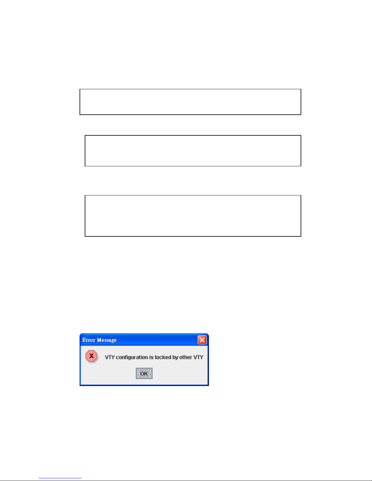
Alert message when multiple users want to configure the switch. If the administrator is in
configuration mode, then the Web users can’t change the settings. The Switch allows only
one administrator to configure the switch at a time.
Switch(config)# a?
access-list Add an access list entry
administrator Administrator account setting
arp Set a static ARP entry
Switch# co (tab) (tab)
Switch# configure terminal
Switch(config)# ac (tab)
Switch(config)# access-list
Switch(config)# interface (?)
IFNAME Interface's name
vlan Select a vlan to configure
26
4.2 Basic Setting
The Basic Setting group provides you to configure switch information, IP address, User
name/Password of the system. It also allows you to do firmware upgrade, backup and
restore configuration, reload factory default, and reboot the system.
Following commands are included in this group:
4.2.1 Switch Setting
4.2.2 Admin Password
4.2.3 IP Configuration
4.2.4 Time Setting
4.2.5 DHCP Server
4.2.6 Backup and Restore
4.2.7 Firmware Upgrade
4.2.8 Factory Default
4.2.9 System Reboot
4.2.10 CLI Commands for Basic Setting
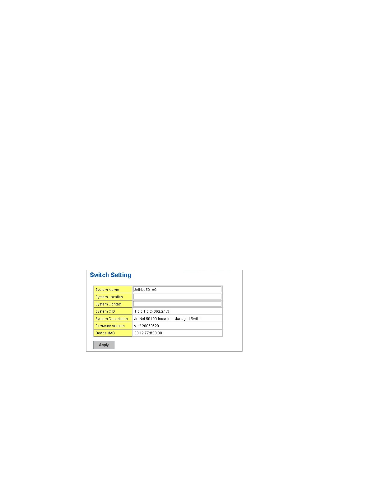
4.2.1 Switch Setting
You can assign System name, Location, Contact and view system information.
Figure 4.2.1.1 – Web UI of the Switch Setting
System Name: You can assign a name to the device. The available characters you can
input is 64. After you configure the name, CLI system will select the first 12 characters as
the name in CLI system.
System Location: You can specify the switch’s physical location here. The available
characters you can input are 64.
System Contact: You can specify contact people here. You can type the name, mail
address or other information of the administrator. The available characters you can input
are 64.
System OID: The SNMP object ID of the switch. You can follow the path to find its private
MIB in MIB browser. (Note: When you attempt to view private MIB, you should compile
private MIB files into your MIB browser first.)
 Loading...