

KOREL M2OC-18HFN8-Q, M2OD-18HFN8-Q, M3OF-21HFN8-Q, M2OG-14HFN8-Q, M3OF-27HFN8-Q Service Manual
...
SERVICE MANUAL
TEHNIČKI PRIRUČNIK
KOREL AIRCONDITIONER
EUROPE MARKET
SUPER DC INVERTER MULTI TYPE
M2OG-14HFN8-Q = X
M2OC-18HFN8-Q = K20C-18FN8 = K20C-18HFN8
M2OD-18HFN8-Q =x
M3OF-21HFN8-Q = K30-21FN8
M3OF-27HFN8-Q = K30-27FN8 = K30-37HFN8
M3OE-27HFN8-Q = x
M4OB-36HFN8-Q = K40-36HFN8
M5OD-42HFN8-Q = K50-42FN8
M4OE-28HFN8-Q = X
DC MULTI OUTDOOR UNITS

CONTENTS
1. General information of Outdoor Units .................................. 2
2. Features .................................................................................. 3
3. Dimensions ............................................................................. 4
4. Refrigeration Cycle Diagram ................................................. 5
5. Wiring diagram ....................................................................... 7
6. Indoor units combination .................................................... 14
7. Sound Levels ........................................................................ 16
8. Installation Details ............................................................... 17
8.1 Wrench torque sheet for installation ........................................................................... 17
8.2 Connecting the cables ................................................................................................ 17
8.3 Pipe length and the elevation ..................................................................................... 17
8.4 Installation for the first time ......................................................................................... 18
8.5 Adding the refrigerant after running the system for many years ................................ 21
8.6 Re-installation while the indoor unit need to be repaired ........................................... 22
8.7 Re-installation while the outdoor unit need to be repaired ......................................... 24
9. Electronic control function .................................................. 26
10. Troubleshooting ................................................................. 31
Caution: Risk of fire/flammable materials
1

1. General information of Outdoor Units
Model name
Dimension (mm)
Compressor
M2OG-14HFN8-Q
800x333x554
KSN140D21UFZ
M2OC-18HFN8-Q
800x333x554
KSM135D23UFZ
M2OD-18HFN8-Q
800x333x554
KSN140D21UFZ
M3OF-21HFN8-Q
845x363x702
KSN140D21UFZ
M3OE-27HFN8-Q
845x363x702
KTF235D22UMT
M3OF-27HFN8-Q
845x363x702
KTM240D57UMT
M4OB-36HFN8-Q
946x410x810
KTF310D43UMT
M4OE-28HFN8-Q
946x410x810
KTM240D57UMT
M5OD-42HFN8-Q
946x410x810
KTF310D43UMT
2

2. Features
The hydrophilic fin can improve the heating efficiency at operation mode.
It protects the valves and prevents water from dripping.
4 way valve control
It is only operated in the heating operation mode except defrosting operation.
Outdoor unit
Power relay control
Hydrophilic aluminum fin
Anti-rust cabinet
Valve protection cover
Low noise air flow system
Discharge pipe temperature protection
3
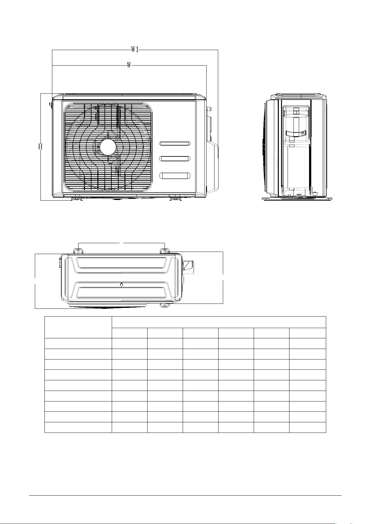
3. Dimensions
Model
Unit:mm
W D H
W1 A B
M2OG-14HFN8-Q
800
333
554
860
514
340
M2OC-18HFN8-Q
800
333
554
860
514
340
M2OD-18HFN8-Q
800
333
554
860
514
340
M3OF-21HFN8-Q
845
363
702
923
540
350
M3OE-27HFN8-Q
845
363
702
923
540
350
M3OF-27HFN8-Q
845
363
702
923
540
350
M4OE-28HFN8-Q
946
410
810
1034
673
403
M4OB-36HFN8-Q
946
410
810
1034
673
403
M5OD-42HFN8-Q
946
410
810
1034
673
403
A
B
D
4

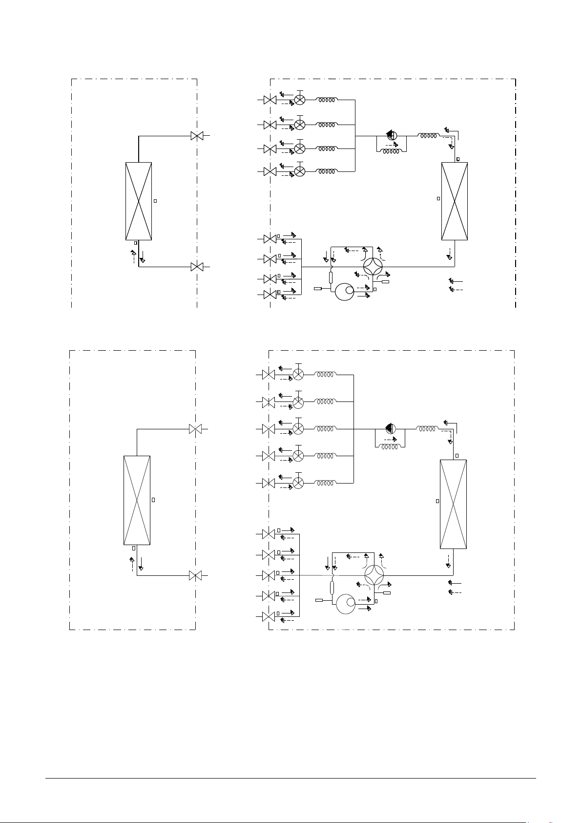
4. Refrigeration Cycle Diagram
L IQ U I D V A L V E A
G A S V A LV E A
H E A T
E X C H A N G E
(E V A P O R A T O R )
H E A T
E X C H A N G E
(C O N D E N S E R )
C o m p re s so r
4 -W A Y V A L V E
C O O L I N G
H E A T IN G
T 2 E v a p o ra t o r
te m p . s e n s or
m id d le
T 1 R o o m
te m p . s e n s or
T3
C o n d e n s e r
te m p . s e n s or
T 5 D is ch a rg e
te m p . s e n s or
T 4 A m b ie n t
te m p . s e n s or
IN D O O R O U T D O O R
E X V A
C A P IL L A R Y A
C H E C K V A L V E
C A P IL L A R Y T U B E
E X V B
C A P IL L A R Y B
L IQ U I D V A L V E B
G A S V A LV E B
A c c u m u la t o r
T 2 B -A E va p o ra to r
te m p . s e n so r ou tle t
T 2 B -B
L IQ U I D V A L V E A
G A S V A L V E A
H E A T
E X C H A N G E
(E V A P O R A T O R )
H E A T
E X C H A N G E
(C O N D E N S E R )
C o m p r e s so r
4 -W A Y V A L V E
C O O L IN G
H E A T IN G
T 2 E v a po r a to r
te m p . s e n s o r
m id dle
T 1 R o o m
te m p . s e n s o r
T3
C o n d en s er
te m p . s e n s o r
T 5 D isc h arg e
te m p . s e n s o r
T 4 A m b ie n t
te m p . s e n s o r
IN D O O R O U T D O O R
E X V A
C A P IL L A R Y A
C H E C K V A L V E
C A P IL L A R Y T U B E
E X V B
C A P IL L A R Y B
L IQ U I D V A L V E B
G A S V A L V E B
E X V C
C A P IL L A R Y C
L IQ U I D V A L V E C
G A S V A L V E C
A c c u m u la t o r
T 2 B - A E va p o ra to r
te m p . s e n s o r o u t le t
T 2 B -B
T 2 B -C
4.1 Refrigeration circuit drawing of inverter 1 drive 2 type
4.2 Refrigeration circuit drawing of inverter 1 drive 3 type
5
4.3 Refrigeration circuit drawing of inverter 1 drive 4 type
L IQ U ID V A L V E A
G A S V A L V E A
H E A T
E X C H A N G E
(E V A P O R A T O R )
H E A T
E X C H A N G E
(C O N D E N S E R )
C o m p re s s o r
4 -W A Y V A L V E
C O O L IN G
H E A T IN G
T 2 E v a p o ra to r
te m p . s e ns o r
m i d d le
T 1 R o o m
te m p . s e ns o r
T3
C o n d e ns e r
te m p . s e ns o r
T 5 D is ch a rge
te m p . s e ns o r
T 4 A m bie n t
te m p . s e ns o r
IN D O O R O U T D O O R
E X V A
C A P I L L A R Y A
C H E C K V A L V E
C A P I L L A R Y T U B E
E X V B CA P IL L A R Y B
L IQ U ID V A L V E B
G A S V A L V E B
E X V C
C A P I L L A R Y C
L IQ U ID V A L V E C
G A S V A L V E C
E X V D C A P I L L A R Y D
L IQ U ID V A L V E D
G A S V A L V E D
A c c u m u la t o r
H ig h p r e s s u re
sw itc h
L o w p re s sure
sw itc h
T 2 B -A E v a p o ra to r
te m p . se n s o r o u t le t
T 2 B -B
T 2 B -C
T 2 B -D
L IQ U ID V A L V E A
G A S V A L V E A
H E A T
E X C H A N G E
(E V A P O R A T O R )
H E A T
E X C H A N G E
(C O N D E N S E R )
C O O L IN G
H E A T IN G
T 2 E v a p ora t o r
te m p . s en s o r
m id d le
T 1 R o o m
te m p . s en s o r
T3
C o n d e n s e r
te m p . s en s o r
T 4 A m b ie n t
te m p . s en s o r
IN D O O R O U T D O O R
E X V A C A P IL L A R Y A
C H E C K V A L V E
C A P IL L A R Y T U B E
E X V B
C A P IL L A R Y B
L IQ U ID V A L V E B
G A S V A L V E B
E X V C
C A P IL L A R Y C
L IQ U ID V A L V E C
G A S V A L V E C
E X V D
C A P IL L A R Y D
L IQ U ID V A L V E D
G A S V A L V E D
E X V E
C A P IL L A R Y E
L IQ U ID V A L V E E
G A S V A L V E E
C o m p re s so r
4 -W A Y V A L V E
T 5 D is c h a rg e
te m p . s en s o r
A c c u m u l a to r
H ig h p res s u r e
sw itc h
L o w p re s s ure
sw itc h
T 2 B - A E va p o r a t o r
te m p . s e n s o r ou t le t
T 2 B -B
T 2 B -C
T 2 B -D
T 2 B -E
4.4 Refrigeration circuit drawing of inverter 1 drive 5 type
6
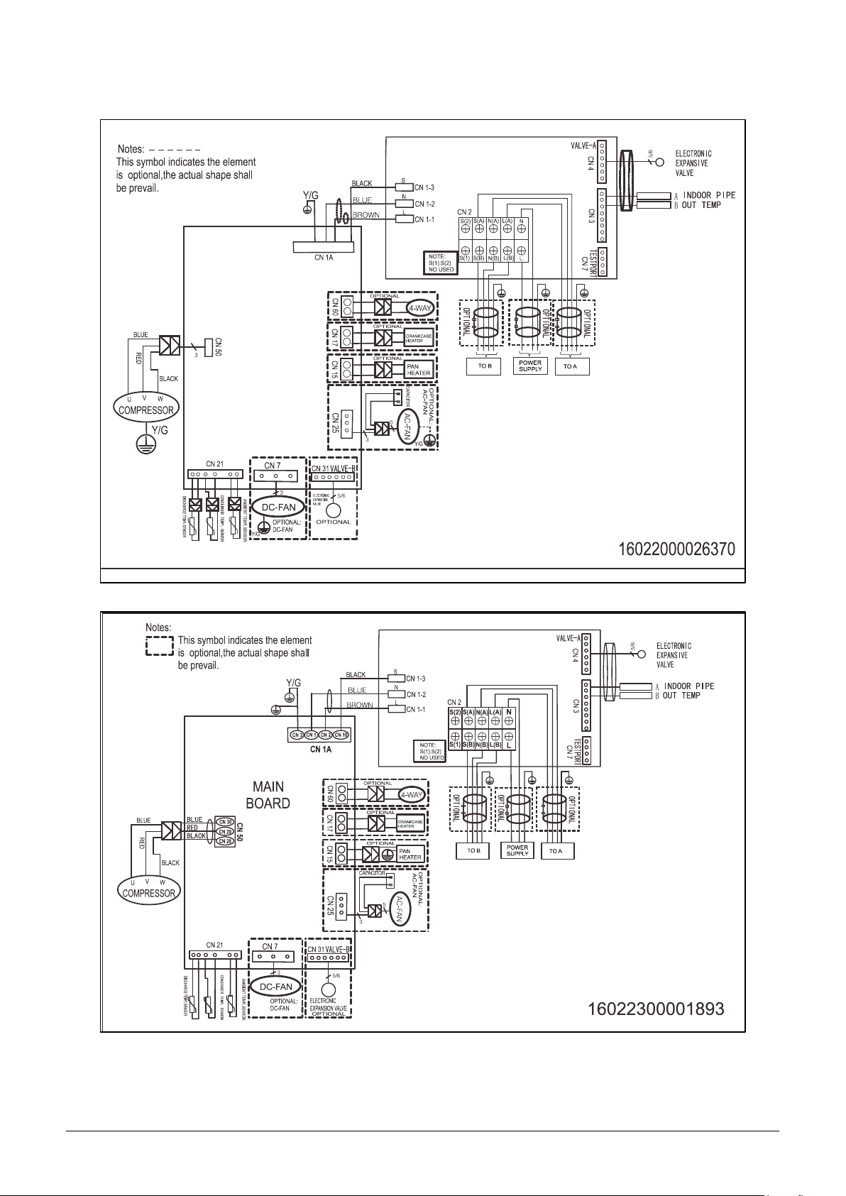
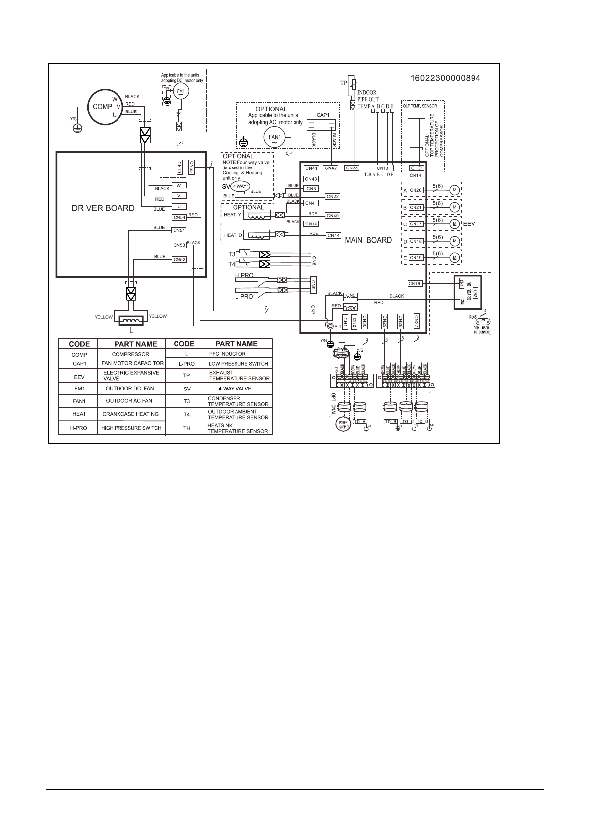
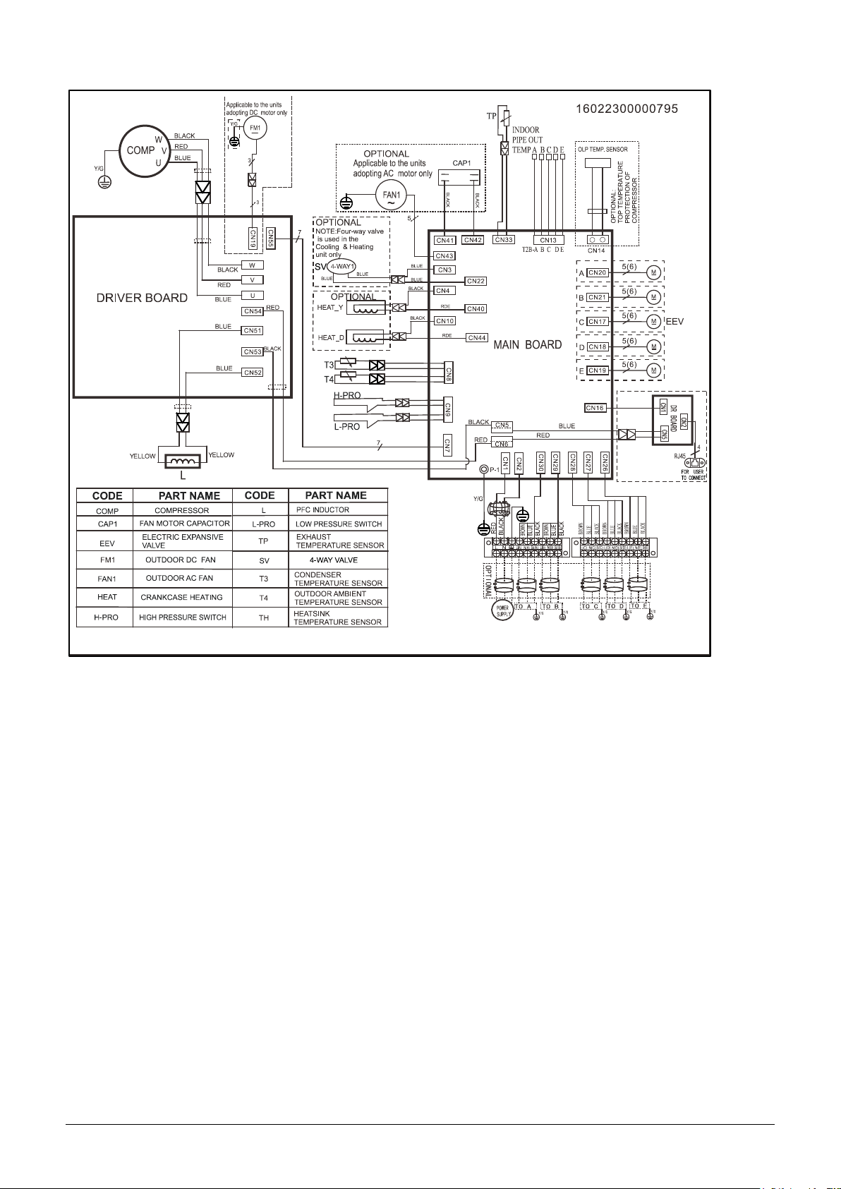
5. Wiring diagram
M2OC-18HFN8-Q
M2OG-14HFN8-Q
7

M2OD-18HFN8-Q
8

Note: S(1)&S(2) are used in other type of models. They don't need to be connected in multi models.
9

M3OE-27HFN8-Q
10

M3OF-21HFN8-Q, M3OF-27HFN8-Q
M4OE-28HFN8-Q
11
M4OB-36HFN8-Q
12
M5OD-42HFN8-Q
13
One unit
Two unit
7
7+7
9+9
9
7+9
9+12
12
7+12 18
One unit
Two unit
7
7+7
9+9
9
7+9
9+12
12
7+12
12+12
18
One unit
Two unit
Three unit
7
7+7
9+9
7+7+7
7+9+9
9
7+9
9+12
7+7+9
9+9+9
12
7+12
9+18
7+7+12
18
7+18
12+12
One unit
Two unit
Three unit
7
7+7
7+18
9+18
7+7+7
7+9+12
9+12+12
9
7+9
9+9
12+12
7+7+9
7+12+12
12+12+12
12
7+12
9+12
12+18
7+7+12
9+9+9
18 7+9+9
9+9+12
Two unit
Three unit
Four unit
7
7+7
9+9
12+18
7+7+7
7+9+12
9+9+18
7+7+7+7
7+7+9+12
9
7+9
9+12
12+24
7+7+9
7+9+18
9+12+12
7+7+7+9
7+9+9+9
12
7+12
9+18
18+18
7+7+12
7+12+12
12+12+12
7+7+7+12
9+9+9+9
18
7+18
9+24
7+7+18
9+9+9
7+7+9+9
24
7+24
12+12
7+9+9
9+9+12
6. Indoor units combination
6.1 Indoor unit combination for M2OG-14HFN8-Q
6.2 Indoor unit combination for M2OC-18HFN8-Q&M2OD-18HFN8-Q
6.3 Indoor unit combination for M3OE-21HFN1-Q
6.4 Indoor unit combination for M3OE-27HFN8-Q&M3OF-27HFN8-Q
6.5 Indoor unit combination for M4OE-28HFN8-Q
14
One Unit
Two Unit
Three Unit
7
7+7
9+18
7+7+7
7+9+18
9+9+12
12+12+12
9
7+9
9+24
7+7+9
7+9+24
9+9+18
12+12+18
12
7+12
12+12
7+7+12
7+12+12
9+9+24
12+12+24
18
7+18
12+18
7+7+18
7+12+18
9+12+12
12+18+18
24
7+24
12+24
7+7+24
7+12+24
9+12+18
9+9
18+18
7+9+9
7+18+18
9+12+24
9+12
7+9+12
9+9+9
9+18+18
Four Unit
7+7+7+7
7+7+9+18
7+9+9+12
7+12+12+12
9+9+12+18
7+7+7+9
7+7+9+24
7+9+9+18
7+12+12+18
9+9+12+24
7+7+7+12
7+7+12+12
7+9+9+24
9+9+9+9
9+12+12+12
7+7+7+18
7+7+12+18
7+9+12+12
9+9+9+12
9+12+12+18
7+7+7+24
7+7+12+24
7+9+12+18
9+9+9+18
12+12+12+12
7+7+9+9
7+7+18+18
7+9+12+24
9+9+9+24
12+12+12+18
7+7+9+12
7+9+9+9
7+9+18+18
9+9+12+12
Five Unit
7+7+7+7+7
7+7+7+9+18
7+7+9+12+12
7+9+9+9+18
9+9+9+12+12
7+7+7+7+9
7+7+7+12+12
7+7+9+12+18
7+9+9+12+12
9+9+12+12+12
7+7+7+7+12
7+7+7+12+18
7+7+12+12+12
7+9+12+12+12
7+7+7+7+18
7+7+9+9+9
7+7+12+12+18
9+9+9+9+9
7+7+7+9+9
7+7+9+9+12
7+9+9+9+9
9+9+9+9+12
7+7+7+9+12
7+7+9+9+18
7+9+9+9+12
9+9+9+9+18
Two unit
Three unit
Four unit
7
7+7
9+18
7+7+7
7+9+12
7+18+18
9+12+18
7+7+7+7
7+7+9+12
7+9+9+12
9+9+9+12
9
7+9
9+24
7+7+9
7+9+18
9+9+9
9+12+24
7+7+7+9
7+7+9+18
7+9+9+18
9+9+9+18
12
7+12
12+12
7+7+12
7+9+24
9+9+12
9+18+18
7+7+7+12
7+7+12+12
7+9+12+12
9+9+12+12
18
7+18
12+18
7+7+18
7+12+12
9+9+18
12+12+12
7+7+7+18
7+7+12+18
7+12+12+12
9+12+12+12
24
7+24
12+24
7+7+24
7+12+18
9+9+24
12+12+18
7+7+9+9
7+9+9+9
9+9+9+9
12+12+12+12
9+9
18+18
7+9+9
7+12+24
9+12+12
9+12
6.6 Indoor unit combination for M4OB-36HFN8-Q
6.7 Indoor unit combination for M5OD-42HFN8-Q
15
Model
Noise Power dB(A)
Noise level dB(A)
M2OG-14HFN8-Q
64
57
M2OC-18HFN8-Q
56
53
M2OD-18HFN8-Q
65
55.5
M3OF-21HFN8-Q
66
57.5
M3OE-27HFN8-Q
65
59
M3OF-27HFN8-Q
67
59.5
M4OE-28HFN8-Q
69
61
M4OB-36HFN8-Q
68
63
M5OD-42HFN8-Q
71
62
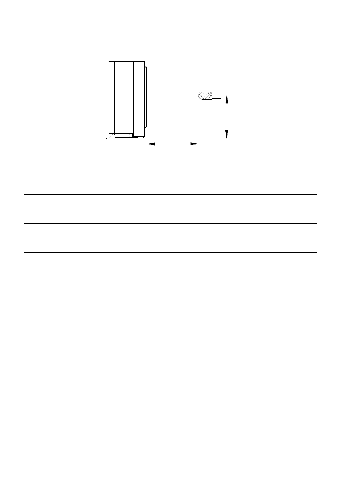
H
1.0m
Outdoor Unit
Microphone
7. Sound Levels
Note: H= 0.5 × height of outdoor unit
16
Outside diameter
Torque
Additional tightening torque
mm
N.cm
N.cm
Ф6.35
1500(153kgf.cm)
1600(163kgf.cm)
Ф9.52
2500(255kgf.cm)
2600(265kgf.cm)
Ф12.7
3500(357kgf.cm)
3600(367kgf.cm)
Rated current of appliance
Nominal cross-sectional area (mm²)
>3 and ≤6
0.75
>6 and ≤10
1
>10 and ≤16
1.5
>16 and ≤25
2.5
1 drive 2
1 drive 3
1 drive 4
1 drive 5
Max. length for all rooms (m)
40
60
80
80
Max. length for one IU (m)
25
30
35
35
Max. height difference between IU and OU (m)
15
15
15
15
Max. height difference between IUs (m)
10
10
10
10
1 drive 2
1 drive 3
1 drive 4
1 drive 5
Chargeless pipe
length (m)
15
22.5
30
37.5
Additional
refrigerant charge
(g)
12 x (length for all
rooms - 15)
12 x (length for all
rooms – 22.5)
12 x (length for all
rooms - 30)
12 x (length for all
rooms – 37.5)
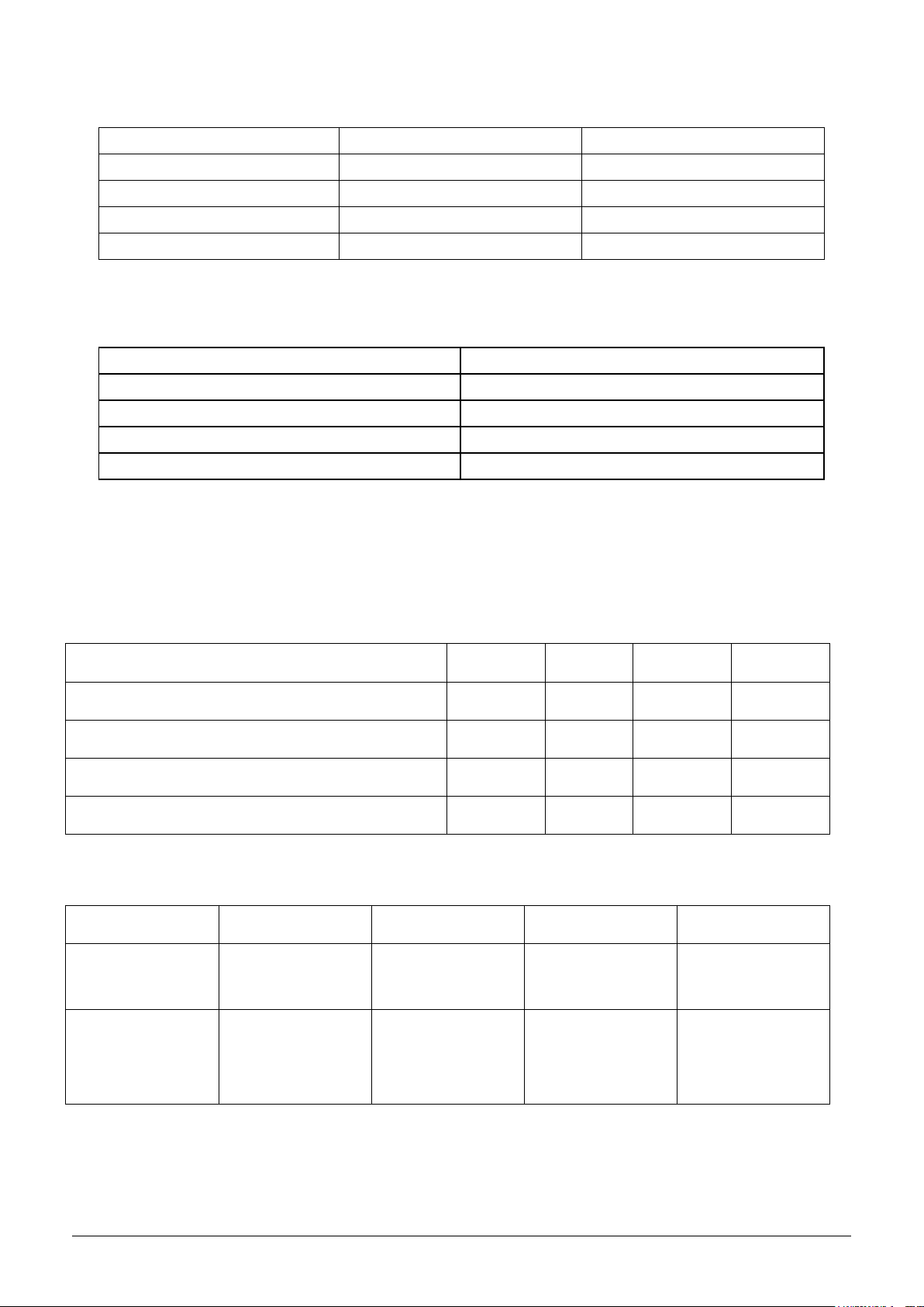
8. Installation Details
8.1 Wrench torque sheet for installation
8.2 Connecting the cables
The power cord of connect should be selected according to the following specifications sheet.
The cable size and the current of the fuse or switch are determined by the maximum current indicated on the
nameplate which located on the side panel of the unit. Please refer to the nameplate before selecting the
cable, fuse and switch.
8.3 Pipe length and the elevation
Maximum piping length and height difference
Additional refrigerant charge
Caution:
● Refrigerant pipe diameter is different according to indoor unit to be connected. When using the
extension pipe, refer to the tables below.
17
 Loading...