

Manual and Technical Documentation TRANSICORD
as of software revision 6.0
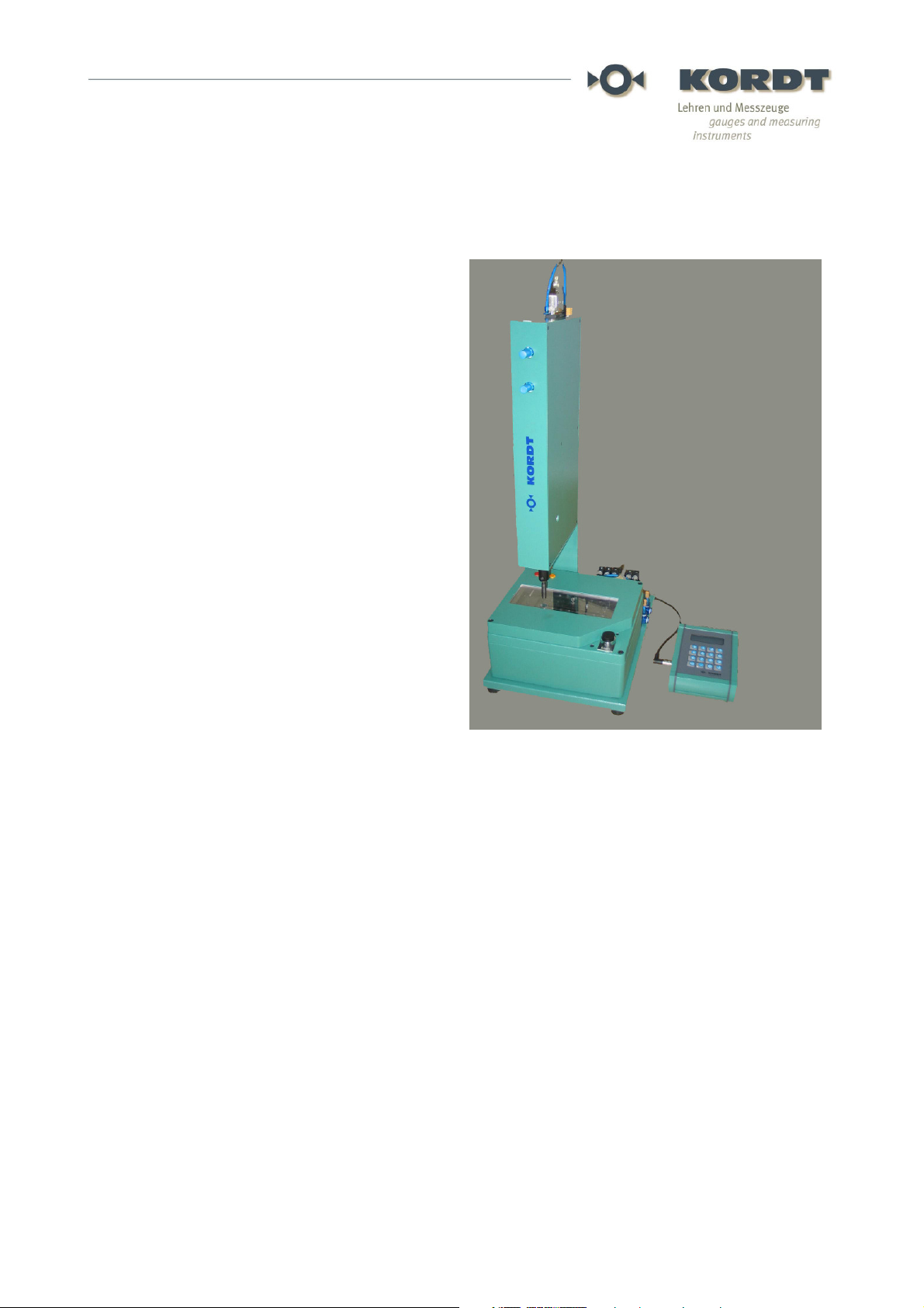
TRANSICORD 10480 V2 is a testing module for
the installation in fully automatic checking and
sorting units or transfer lines as well as for use
in the semi-automatic fixtures.
TRANSICORD 10480 V2 serves for the fast,
standard-compliant and fully automatic gauging
of external and internal threads as well as for
process monitoring in the thread production. Via
opto-isolated interfaces data and parameters are
exchanged with a primary control (SPC) and
serve to process control and documentation.
Strong construction paired with a precise
measuring technology ensure a lowmaintenance use under industry conditions and
provide reliable, reproducible test results.
TRANSICORD 10480 V2 has been developed
for the continuous use.
TRANSICORD 10480 V2 is a self-sufficient,
processor-controlled functional unit. All mobile
axes and the control are integrated. Only the
rack and the component transport with clamping
unit have to be applied according to the specifications. Test sequences are started by an external
start signal and run automatically. All messages and test results are distributed to the interface.
Most metric thread standard thread members are on stock or can be supplied with a short delivery
time. Special thread members can be supplied also: Details on this in chapter 2.
To guarantee a trouble-free operation and exclude damages at the equipment and injuries, please
read this technical documentation carefully before the installation of the device. Follow particularly
the instructions for safety and installation.
®
10480 V2
BA 10480 V2 E 0512/LTA
KORDT GmbH & Co. KG
Fabrik für Lehren und Messzeuge
Preyerstrasse 24 – 26
D - 52249 Eschweiler
Tel.: +49 (0) 2403-7005-0
Fax: +49 (0) 2403-7005-26
email: mail@kordt.de
http//www.kordt.de
1/27

Table of Contents:
1. Extent of supply
2. Gauge members for TRANSICORD 10480 V2
3. Safety instructions
4. General indications for the operation
5. Installation
5.1 Mechanical setup of the testing unit TRANSICORD 10483 V2
5.2 Connection of the control module TRANSICORD 10482
5.3 Connection to SPC
5.4 Power supply
5.5 Adjusting of the compressed air chokes
6. Compensation head TRANSICORD 10002
7. Setting the testing program
7.1 General instructions for the control module
7.2 Description of the menu
7.3 Loading data set
7.4 Starting program
7.5 Statistics
8. Interfaces
9. Running the machine without control module
10. Maintenance
11. Technical specification TRANSICORD 10480 V2
12. Dimensions TRANSICORD 10483 V2
13. Connection plan
14. EU - Installation explanation and EMV - Declaration of Conformity
BA 10480 V2 E 0512/LTA
2/27

1. Extent of supply
TRANSICORD 10480 V2 is delivered with the following components:
• Testing unit TRANSICORD 10483 V2
• Compensation head TRANSICORD 10002. The compensation head of TRANSICORD
10002 LH is used for left-hand threads. Please indicate at the order.
• Control module TRANSICORD 10482 with wall mount
• Interconnecting cable TRANSICORD 10484 to connect the testing unit with the control
module (2 m)
• Connector TRANSICORD 10485 to receive the power supply cable
• this technical documentation
Optional accessories:
Unregulated mains adapter/power supply TRANSICORD 10486 V2, 48 VDC – 12.5 A,
for control cubicle installation
BA 10480 V2 E 0512/LTA
3/27

2. Gauge members for TRANSICORD 10480
TRANSICORD 10480 is build for reception of the following CORD gauge members listed
below. CORD Go gauge members are designed that the first full flank is exact ½ pitch from
the face of the member. The special design of the CORD thread members supply a long
live time and reliability and so secure a repeatable test result. The CORD NoGo gauge
members have a guiding thread of two pitch length.. Hence the first full thread is at 2,5xP
from the face of the gauge member.
Most standard metric gauge members are deliverable from stock or can be delivered with a
short delivery time. On request we supply special design gauge members according to your
workpiece drawing.
Thread Go gauge member TRANSICORD 10960
l2: according DIN 2282
le: max. screw in length
l: total length
Thread limit gauge member TRANSICORD 10961
le: screw in length
l2: according DIN 2282 and DIN 2284
l3: length of intermediate thread
le: max. screw in length
l: total length
Limit gauge thread member TRANSICORD 10963
l2: according DIN 2284
le: max. screw in length
l: total length
BA 10480 V2 E 0512/LTA
4/27
Ø D
Ie
Nominal diameter of
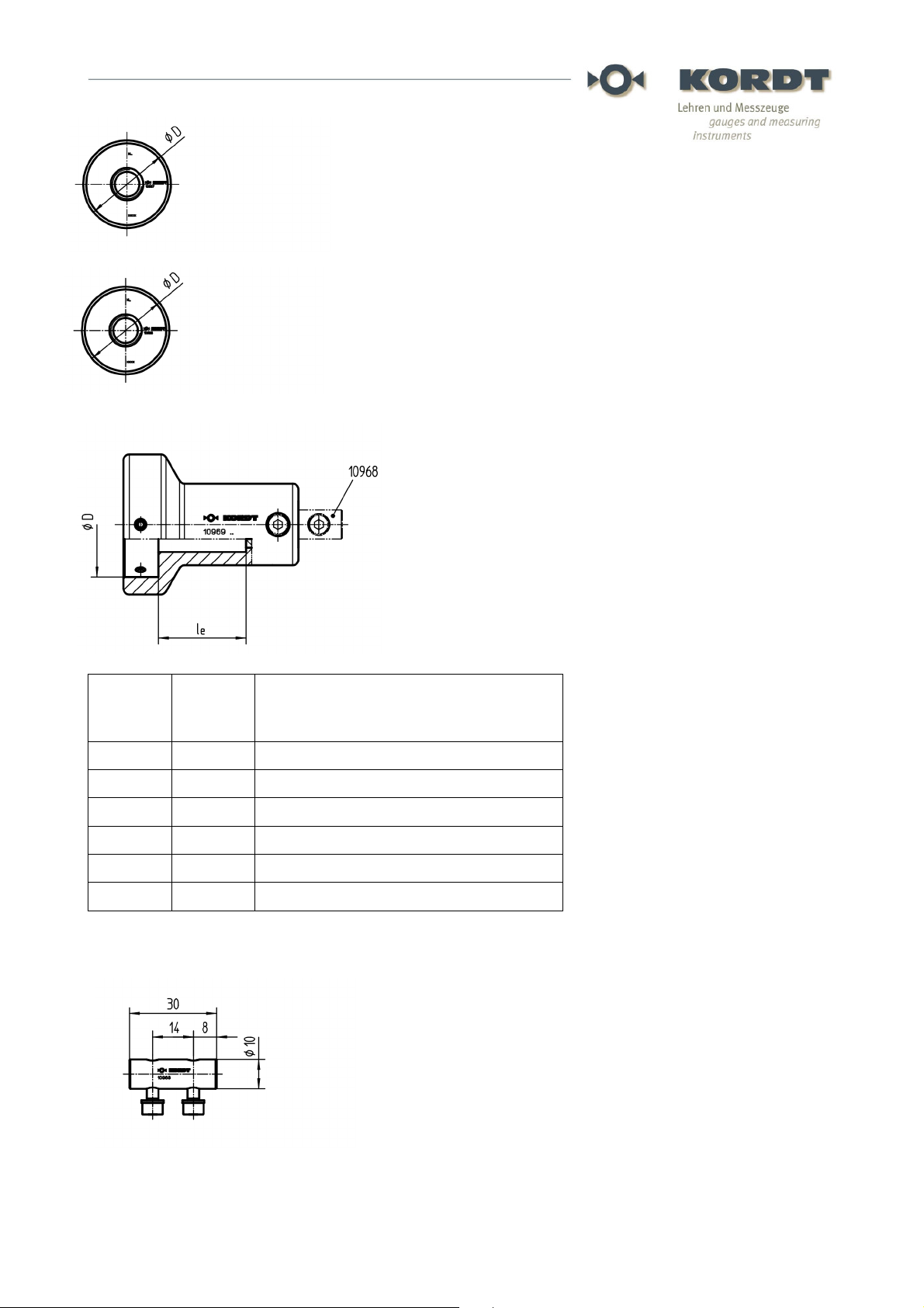
Thread Go gauge ring TRANSICORD 10967
Thread NoGo gauge ring TRANSICORD 10966
Reception TRANSICORD 10969
for thread gauge ring TRANSICORD 10967 and
10966.
[mm]
[mm]
TRANSICORD thread gauge rings
[mm]
20 23 2 – 5,5
30 26 5,5 – 10
36 30 10 - 15
43 31 16 – 20
51 31 21 – 25
61 39 26 - 30
Connection piece TRANSICORD 10968
to connect compensation head TRANSICORD
10002 and reception TRANSICORD 10969
BA 10480 V2 E 0512/LTA
5/27

3. Safety instructions
Caution! For the use of equipment driven electrically are the following fundamental
security procedures for protection against blow, injury and danger of fire to be taken
into account.
Read and follow these notes before you use the device.
Keep the safety instructions well.
3.1 Keep your area of work tidy. Disorder in the field of work yields causing danger of
accident.
3.2 Take into account surroundings influences. Do not expose the equipment to damp
or wet environment. Do not use the equipment in the near of combustible liquids,
liquids or gas. Provide a good illumination.
3.3 Protect yourself from an electric blow. Avoid to touch not earthed parts.
3.4 Keep third persons away! Keep other persons away from your field of work.
3.5 Do not overload your device. You work better and saver in the described performance
area.
3.6 Use the right tool. Do not use a too weak equipment, clamping devices or feeding
units. Do not use equipment for purposes and work for which it is not intended.
3.7 Wear a suitable working clothes. Wear no far clothes or jewellery. You can be
included or captured by moving parts.
3.8 Do not misuse the cables. Do not carry the device at the cable and do not use it to
unplug the plug from the electrical outlet. Protect the cable from heat and sharp edges.
3.9 Secure the component. Use clamping devices and feeding units or vice around the
component to hold the component tight. It is kept thus safer than with your hand and makes
the operation of the device possible with both hands.
3.10 Do not bend your stand. Avoid an abnormal posture. Provide a safe state and keep
the balance any time.
3.11 You keep your equipment in good condition and handle with care.
Pay attention to cleanness and rust protection to work for certain and well. . Follow the
maintenance regulations and the notes for tool changes and accessories.
Check the plug and the cable regularly and let these damages replaced by an expert . Keep
grips dry and free of oil and grease.
3.12 Unplug the mains plug if you are not using it, before the maintenance and other work
on the device.
3.13 Do not leave a tool key. Before switching on, check that the keys and setting tools
are removed.
3.14 Avoid an unintentional start. Do not carry an equipment connected to the power
supply system or with a finger at the switch. Make sure that the switch is turned off at the
terminal connection to the power supply system.
3.15 Be always attentive. Watch your work. Proceed sensibly. Follow the notes of the
operator. Do not use the device if you are lacking in concentration.
3.16 Check your device on damages. All parts must be put together correctly and satisfy
all conditions to ensure the faultless operation of the device. Damaged safety devices or
parts should be repaired by our customer services or are repaired or replaced according to
the instructions as far as nothing else is indicated in the operating instructions. Faulty parts
only may be in working order put or replaced by suitable specialist staff. Do not use an
equipment if the switch on/off is broken. Only use KORDT original parts.
3.17 Accessories
You use only accessories and options for your safety which are indicated in this technical
documentation. The use of others than this one in the technical documentation or use tools
or accessories not recommended in the catalogue can mean a personal injury danger for
BA 10480 V2 E 0512/LTA
6/27

you.
3.18 Installation
Have particularly the electrical installation of the device executed only of specialist staff. A
faulty connection of the device represents a danger for persons. Disturbances and
damages cannot be excluded at a faulty installation. Use our offer of putting into operation.
3.19 General
Not authorized changes, mishandling or -setting as well as not attention of the manual a
liability of the manufacturer for all damages excludes.
3.20 Care
The testing machine with its accessories should be cleaned in fixed cycle and protected
against corrosion at the shiny areas. The used gauge member (thread gauge) must be oiled
regularly in the operation. Gauge members should be managed and brought to the
recalibration in the context of a general control of measuring and testing equipment.
3.21 Control of measuring and testing equipment
For your control of measuring and testing equipment to ISO 9000 pp. we offer you our
KORDT-Calibrating Service (KKS).
4. General notes for operation
TRANSICORD 10480 V2 consists of 2 devices: The testing unit TRANSICORD 10483 V2
and the control module TRANSICORD 10482.
The testing unit TRANSICORD 10483 V2 has an axially mobile turning spindle which is
driven with a very dynamic, brushless servomotor. The axial movement of the turning
spindle is steered with compressed air. On the end of this spindle the compensation head
TRANSICORD 10002 is fastened. The compensation head compensates small position and
angular errors of the tested work-piece. The compensation head is also used for receiving
the thread gauge member. Before the testing sequence starts the thread to be checked
must be placed aligned to the turning spindle and fixed against rotation. The examining
process is started by an electrical start signal.
The handy control module TRANSICORD 10482 is connected to the testing unit with a
signal cable and serves for the manual setting of the examining process as well as
displaying results and reports. The control module can mounted user friendly at an
accessible place.
TRANSICORD 10480 V2 screws in the thread gauge member after receiving an external
start signal. It controls the testing procedure with the measurement of the length of the
screw in and the torque used.
TRANSICORD 10480 V2 tests external and internal thread attributive. With other words the
result of the tests will be „Go“, „NoGo“ and „Rework“.
The result is shown on the display when the testing procedure has finished. It will be
distributed via an optocoupler interface (see chapter 8). The display will freeze till the next
result is received. Alternatively the result can also be read out via optocoupler isolated TTY
interface. The TTY has the benefit that the thread depth and the torque can be read out in
addition. Furthermore all parameters can be transferred through this interface in two
directions. Statistics about the test results are shown at the display.
The following tests can be carried out:
• Go gauging
• Go gauging with thread depth measurement
• NoGo gauging
BA 10480 V2 E 0512/LTA
7/27

• Limit / Go-NoGo gauging (for through taped internal thread only)
On one hand the test result depends whether the set, maximum torque of screw in is
reached (see chapter. 7.2.5). On the other hand, it is dependent how far the gauge member
can be screwed in.
For the screw in procedure different testing levels control the behaviour of the testing unit:
T0 = Base level of the spindle (not turning of the spindle)
T1 = Start of the thread according to the component drawing.
T2 = Minimum depth at the Go gauging. T2 must be reached before the result „GUT“
(Go) can be generated. If T2 is not reached, the result will be „NA“ for Rework.
T3 = Maximal depth for the NoGo gauging. If T3 is reached the result will be „AUS“
for NoGo.
TR = From this level the rotation speed will be reduced to the inserting speed. The
rotation speed should be reduced before the level T2, resp. T3 is reached. At T2 or
T3 the gauge normally will run tight. To save gauges and avoid blocking of the
machine due to tightening at high speed and torque the speed should be reduced
before running tight usually.
5 Installation
5.1 Mechanical setup of the testing unit TRANSICORD 10483 V2
In principle, the testing unit can be put in all orientations. Take special care, however, when
checking below up that no dirt and liquid can penetrate into the spindle case. These can cause
disturbances in the long run. Please gather the necessary connection measures to the fastening
from the drawing in chapter 11. An adjustable connection console is recommended in order to align
the spindle to the component in the fixture.
The compensation head allows wrong position of the thread axis of the component to the spindle
axis of maximal 0.6 mm and 0.6 degrees. The more exactly the component is placed the less
friction you have at the testing procedure.
Fasten the thread gauge member on the compensation head. Before you can alternatively screw in
the gauge member into the component and pull the spindle at the gauge to check the alignment of
the spindle to component (only permitted without power supply and compressed air connection!).
Take care that the most possible, mechanical lift of the spindle is never exceeded. Take also in
account that faulty parts may require longer lift. We recommend a distance of approx. 5 mm
between the gauge and the component surface when the spindle is fully lifted (base level T0.) Pay
attention to the possible collision risks in automatic and setting mode!
As the component mostly is dimensioned form its face make sure that the thread start is always
fixed in the same position and will not be influenced of tolerances of other measures of the
component. Otherwise the component tolerances have influence on the thread depth measuring
and influence the test result. Pay attention to a good clamping so it will not break out by stress
during the testing process. A good clamping will guarantee a good test result of the thread depth
measurement.
Take care that it can never come to collisions at the work-piece transport. Heavy damages are
inevitably the consequence. Therefore the work-piece only may be moved when the spindle is fully
back and in base level (T0) and the "Ready" signal is shown(see chapter 5-3-1 and chapter 8).
Take possible errors also into you calculation (e.g. compressed air, power supply, failure of
components).
BA 10480 V2 E 0512/LTA
8/27

Connect the testing unit via an air maintenance unity to the compressed air supply when the unit is
mounted and fixed in position. Please adjust 4 to 6 bar. Do not oil the compressed air.
Ensure a regular lubrication of the gauge member. The wear on the gauge is reduced
considerably and extends its life time with that.
5.2 Connection of the Control Module TRANSICORD 10482
Fasten the control module with the enclosed wall mountings to a well accessible place and
connect the testing with the delivered Interconnecting Cable 10484. This has a length of 2
metres. Extend the cable under no circumstances. The proper operation of TRANSICORD
10480 V2 can be ensured only with the original cable.
The control module should remain connected to the testing unit permanently.
Avoid to align the Interconnecting Cable 10484 parallel to high-power cables. Protect
the interconnecting cable against damages by installing it in a cable channel.
5.3 Connection to SPC
Attach the SPC to the testing unit TRANSICORD 10483 V2 according to the appending
terminal connection plan (see chapter 12). Use a shielded cable and apply the screen onesided! Take into account that the optocoupler interface needs a power supply of its own. To
avoid ground loops use two additional wires to connect the optocoupler supply to the SPC
power supply.
Program your SPC so that a trouble-free operation is ensured. Follow the following
instruction in any case:
5.3.1 Testing sequence can only be started when the spindle is in base level (T0), the
„READY“-Signal is supplied and no error occurs.
5.3.2 Power supply faults are detected by TRANSICORD.
5.3.3 Errors are distributed over output "/FEHLER" and shown as a text at on the display.
Follow the announced instructions. Errors can be collected via the TTY interface.
5.3.4 Move the component only when the spindle is in base level (T0), the „READY“ signal is supplied and no error occurs. While the testing sequence is running the
component must be fixed tight.
5.3.5 The result of the test is distributed when the testing sequence is completed and the
spindle is at base level (T0) again. Until the distribution of the next result the present
test results can be collected. In this time period the communication via the TTY
interface also can take place. For safety reasons the TTY interface is only active,
when the testing program is running see chapter 2.4) or the "READY" signal is
displayed (NO IN THE SETTING MODE).
5.3.6 The advices are also important for the setting mode! Draw you attention especially
to a possible collision and a correct clamping and positioning of the components.
Further description you find at chapter 8.
5.4 Power supply
Connect the testing unit to the unregulated power supply TRANSICORD 10486 V2 when you
have finished the pre-work. Use for this the delivered cable connection socket
TRANSICORD 10485 and a three-wire cable with a wire diameter of at least 1.5 mm ², better
2.5 mm ². The line should not be long any more than 5 metres. Also protection ground has to
BA 10480 V2 E 0512/LTA
9/27

be connected.
At use of another power supply this must certainly have a low intrinsic resistance ("stiff output
voltage") to guarantee a trouble-free operation. As a rule, power supplies with toroidal mains
transformer have this quality. Switched power supplies should not be used. Do not attach
other consumers to the power supply. A isolation must be between mains and secondary
side.
5.5 Setting of compressed air throttle
Adjust the speed and damping of the axial spindle movement for the two directions
separately at the compressed air chokes at the testing unit. The air pressure should be 4 to 6
bar. Use the function "spindle" as in chapter 7.2.9.1 described. Set the throttle for the two
directions separately so that the spindle moves speedily but not too fast and well cushioned.
Caution: Injury danger! Keep away from the area of the spindle.
BA 10480 V2 E 0512/LTA
10/27

6 Compensation head TRANSICORD 10002
The compensation head TRANSICORD 10002
evens small position and angle offsets and
reduces the load to the spindle.
Ordering note: If you require the compensation
head for left-hand thread, please indicate at the
order absolutely! The TRANSICORD
compensation head for left-hand threads has the
type number 10002 LH.
Setting:
The compensation head is assembled together
with the bore ø10 lying above on the testing
spindle. It compensates small position and
angular errors and reduces the stress on the
spindle. After screwing out of the hexagon
headed screw ISO 4762-M 4 x 12 -12.9 with
spring washer the compensation head can be
pulled off. By turning the thread pin ISO 4026 - M
5 x6 at the lower tape the centring force of the
compensation head can be adjusted according to
the individual situation. Caution! Fasten the
thread pin not too tight, since otherwise the
centring taper can be damaged.
Maintenance: Check regularly the thread pin
10002-17 for deformation. If this is bent, you
exchange the pin (see drawing). Grease the
connection areas of reception and shaft. Release
the connection whenever it is blocked. Clean and
grease junction points before the assembly.
BA 10480 V2 E 0512/LTA
11/27

7 Setup the test program
7.1 General notes for the control module:
All functions and parameters of TRANSICORD 10480 V2 are executed or changed with the
control module 10482. The control module has a 4-line illuminated LC display and a robust
membrane keyboard with 16 buttons.
The numbered menu lines can be selected directly by pressing the number button. On
available, not visible lines point out to little arrows on the right in the display. A keystroke on
the corresponding arrow button rolls the screen in the desired direction.
Letters and special signs being able to be set also when required in text fields over the
number buttons: Press the button quick several times till the desired sign appears.
Line inputs must always be completely carried out until line end. If the last letter is entered,
the new value is stored with the <Enter> button. The <Esc> button rejects the input. An input
terminated can be at any time with the <Esc> button. The previous value reappears. You also
change to the primary menu with<Esc>. The input is checked on plausibility and rejected at
faults.
Manual and setting of the test program
Switching on TRANSICORD a status is pointed with detail of the software version briefly:
TRANSICORD 10480
KORDT GmbH & Co. KG
GERMANY
Version 4.1
Shortly after that a test is executed after confirmation with <Enter>.
Caution! The spindle is moved at this test. Keep away from the danger area.
While the testing sequence errors are displayed. You will be requested to remove these
errors. Only if the function test is finished without error a test program can be started (see
chapter 7.4). After finishing the test sequence TRANSICORD is running in automatic mode
and is waiting for the start signal.
Please push <ESC> to switch to the main menu. TRANSICORD is now in manual mode.
For safety reasons TRANSICORD reacts to the START signal only in automatic mode.
1) Setup
2) Load Test Record
3) Run Program
4) Statistics
BA 10480 V2 E 0512/LTA
12/27

9) Functional Test ↑
To set the program procedure as follows:
Press <1> for Setup:
7.2 Description of the Setup menu:
You see the following displays:
1) Thread Parameters
2) Repitions _
3) n_test ______rpm
4) n_thread_____rpm↓
5) M_max ___ Ncm ↑
6) T1 scan
7) Edit Levels
8) Save Record ↓
Press <1> for
7.2.1 Thread Parameters
7.2.1.1 Diameter
Press <1> again. The cursor jumps into the petition field. Insert the approx. nominal
diameter of the thread. This value will be used for various suggestion values. Finish our
petition with <ENTER>. (Note: Single digit values have to be start with zero). Value from 01
to 99 mm are applicable.
7.2.1.2 Pitch
Press <2> to set the pitch. Proceed like before. You have to enter the pitch with a resolution
of two digits. Values from 0.10 – 9.99 mm are applicable.
1) Nom.Diameter __ mm
2) Pitch _,__ mm
3) RH Thread
4) Go Gauging+Depth
7.2.1.3 Turning direction
Repeat pressing the <3> and you will change the turning direction. Mainly right hand
threads are used. Keep in mind that you need to replace the compensation head to left-
BA 10480 V2 E 0512/LTA
13/27

hand if you change the turning direction to left hand.
7.2.1.4 Gauging mode
Press <4>. If you repeat to press <4> you toggle between:
1. Go gauging
For Go gauging of internal thread testing. The Go thread gauge member CORD 10960 or
for external thread the Go gauge ring CORD 10965 together with the matching reception
CORD 10969 and intermediate piece CORD 10968 are used.
2. Go gauging + depth (Go gauging with measurement the thread length)
For Go gauging of internal thread testing. The Go thread gauge member CORD 10960 or
for external thread the Go gauge ring CORD 10965 together with the matching reception
CORD 10969 and intermediate piece CORD 10968 are used.
3. Limit gauging
For limit gauging of internal thread. The thread limit gauge member CORD 10961 is used.
Limit gauging is only possible with through taped bores.
4. No Go gauging
For NoGo gauging of internal thread. The thread NoGo member CORD 10963 or for
gauging of external thread the thread NoGo gauge ring CORD 10966 together with the
matching reception CORD 10969 and intermediate piece CORD 10968 are used.
Go back to the main menu with <ESC> when you have finished your setting.
7.2.2 Repetitions
If the thread member does not thread itself into the component there are various reasons
possible:
• Defect of the thread start or a chip blocks the entrance
• Gauge member arrives with a high speed on an unlucky spot of the thread
• Component is not proper aligned, etc.
You can set the repetition up to three times to repeat threading the gauge member into the
thread of the component. The spindle will turn back without lifting and will start the
procedure again. Set the repetitions to 0 – 3 times.
7.2.3 n_test (test speed in rpms)
If required you may change the default test speed. Insert a value in rpm. The speed can be
between 100 and 2000 rpm. For your orientation see the default speed. If you choose a
speed to high the test can get uncertain.
7.2.4 n_thread (threading speed in rpms)
To save gauge and component it is recommended to use a slower speed to thread the
gauge. If required you may change thread rotation speed. The insert rotation speed can be
set between 50 and 1000 rpm. The thread speed will accelerate to the test speed when T1
BA 10480 V2 E 0512/LTA
14/27

plus one lead is reached and will decelerate again when TR is reached.
7.2.5 M_max (maximum torque in Ncm)
The required torque depends of various factors: Diameter, pitch, material, lubrication,
thread length, tolerance, tightness between gauge and component etc. Hence the max.
torque has to be set separately. Keep in mind that the required torque might be higher if the
component is not aligned proper or is less lubrication. If the max. torque is reached the
testing sequence will be stopped. According to the spindle position the result of the test will
be distributed.
If required you may change the max. torque. The torque can be set between 20 and 100
Ncm. It is advisable to set the max. torque to the lowest possible value. With this you can
minimize the stress and the wear out of component and gauge. Please take into account
that gauges with small diameters and gauges with extra long shafts may be overloaded and
break. On the other head the test result with a torque set to low will be insecure.
7.2.6 Scan for T1
The face of TRANSICORD gauge members are always designed with 0.5 pitch distance
from the first full flank. Therefore the TRANSICORD gauges are applicable for the thread
depth measurement absolutely. NoGo gauges have an alignment cylinder of two pitch
length. To determine the start of thread of the component the thread gauge member will be
touch the face of the component and read out the value. With this procedure the start of the
thread according to the component drawing is known by the control.
T1 will be scanned
Adjust
setting master
and confirm.
Put in a component without a thread or a setting master and clamp it. Accept this message
with <ENTER> and the spindle will move the gauge member to the surface of the
component or setting master. The value 0.5 x pitch will added and stored as test level T1.
CAUTION: If you change the pitch in the setting the start of thread will not fit anymore. In
this case you have to reset the settings again.
Automatically you will be leaded to „Edit test levels“ (see chapter 7.2.7). According to the
way of gauging the levels T1, T2, T3 and TR will be presented. No relevant levels will be
removed from the screen. Level T1 was, as described above, defined new and all other test
levels will be set to the same value. All previous existing lines will be over written.
The test levels T2, T3 and TR have to be edited according to the component drawing. Work
chronologically. Keep in mind that always the actual, absolute spindle stroke is the basis. To
get the correct values for T2, T3 and TR you have to add the value for T1 to the values you
see in the component drawing.
This procedure might be difficult but the advantage is that there will be never confusion
about the level. Accordingly values larger then 61 mm will not be possible.
See the details in the following chapter.
BA 10480 V2 E 0512/LTA
15/27

7.2.7 Edit test levels
After you have set T1 as described above (see chapter 7.2.6) you can edit the other test
levels.
The test levels will be measured from the reference point at the upper back stop of the
spindle. The test levels have to be edited with a 0.01 mm resolution and will be read out
with that accuracy after the testing sequence.
Not relevant examining levels are removed depending on way of gauging. The plausibility of
the petition values is checked and if necessary mixes up the order of the values. Therefore
enter the examining levels chronologically and with rising values.
The following test levels are given:
T0 = Basic level of the spindle; No turning of the spindle. (fixed, not changeable.)
T1 = Start of the thread according to the component drawing. The thread speed (see
chapter 7.2.4) will be used to level T1 plus one pitch. At this position it is sure that the
thread member has found the start of the thread. Form this point on the speed will
accelerate up to the set test speed.
T2 = Minimum level for Go gauging. T2 have to be reached to generate the result „GUT“.
Set T2 to the minimum thread length of the component. If T2 is not reached the result will
be „NA“ for rework.
T3 = Max. level for NoGo. If the level T3 is reached the result „AUS“ for NoGo will be given.
If you are in the mode „Go gauging with thread length“ the rotation will continue max. two
turns to give also the reading for the thread length also if the tap on the component is to
deep.
TR = Level from which on the reduced rotation speed will be effective. At Go and Limited
gauging the rotation speed should be reduced before T2, resp. T3 is reached. This will save
gauge and component wearing because below T2 or at T3 normally the gauge will tighten
at max. torque. Also this will avoid blocking of the machine when checking with larger
gauges running tight at high speed and high torque. TR will be generated by entering T2 at
the Go gauging modus resp. in the modus NoGo or limit gauging modus automatically by
setting of T3.
7.2.8 Save test record
When you have completed the setting you can save these parameters. You can record up
to four sets of parameters. When have chosen the set no. you can enter name, description
and name of the program. By fast repetitive pushing of the buttons you can enter letters and
special characters. 16 characters can be entered each line.
Be aware that TRANSICORD will not save the set of parameters automatically. It will only
save the settings if you record the values. When you start >TRANSICORD the last actual
and saved test record will be shown.
7.2.9 Functional test
With this function you can test all functions of the instrument.
CAUTION! Danger of injury: The spindle will move and turn! Keep away from the area of
the spindle. Use this function only if you are sure that the spindle can move freely and no
risk of injury is present.
BA 10480 V2 E 0512/LTA
16/27

7.2.9.1 Spindle
If you repetitively press <1> the position of the spindle will toggle: Move forward, hold, move
back. The current status will be displayed. After the spindle has moved forward the length
will be displayed.
7.2.9.2 Drive
If toggling <2> the drive will run or stop. On the display you see the next function.
7.2.9.3 Run sequence
1) Spindle
<measured depth>
3) Drive
4) Test Sequence
To test the set of parameters you have to accept with <Enter> the following message:
A single test sequence will be performed. Make sure that the component is aligned and
firmly fixed. After the test sequence is finished the result of the test will be displayed.
CAUTION! Risk of injury: The spindle moves forward and turns!
With this test sequence the setting is finished.
Do not forget to save the parameters whenever you find the setting proper (see
chapter 7.2.8)!
Press <ESC> to return to the main menu.
7.3 Load test record parameters
Select the test record from the menu. This will load this test record into the actual set of
parameters. Only with the actual set of parameters the program can be run. If you program
TRANSICORD the next time the last actual set of parameters will be loaded. If you change
parameters please keep always in mind that you might have to change the gauge member
and the fixture. If you change the direction of rotation you also have to change the
compensation head TRANSICORD 10002 for the other hand.
Please insert
component and
confirm.
7.4 Run program
With this function TRANSICORD switches from setting mode to automatic mode and is
waiting for the START-Signal to start the test sequence. To start a test sequence the
READY-Signal must be displayed („1“) and simultaneously the /FEHLER-Signal must be
„1“ (/FEHLER is at an Error on „0“!). The READY-Signal is supplied („1“), if the spindle is at
the basic level (T0) and no error occurs.
BA 10480 V2 E 0512/LTA
17/27

CAUTION! The component may only be moved if the READY-Signal is high and
/FEHLER is high. The START-Signal may only be given if the component is aligned
and clamped tight. During the whole test sequence the component must be fixed.
Damages otherwise can damage the instrument and flying parts can injure persons.
While the automatic mode the statistics will be shown on the display (see below)., These
are the same values you can call from the menu (see chapter 7.5 statistics). The TTYinterface is only active in automatic mode due to safety reasons.
7.5 Statistics
At the display you see the number of executed tests and the results of the tests. If you scroll
down the display you see the thread depth of the last test and the torque which is used
between T1 and T2. If you press <1> (Reset) the values will set to zero.
8 Interfaces
All TRANSICORD 10480 V2 interfaces are of optocoupler type. (Terminal occupation see plan
in chapter 13):
• Static inputs:
• START - start test sequence
• CONFIRM - confirm
• IN_0 - spare input
• IN_1 - spare input
• Static outputs:
• GUT - result of test: Go
• AUS - result of test: NoGo
• NA - result of test: Not OK., Rework
• READY - ready for test sequence
• /FEHLER - error, (active low)
• OUT0 - spare output
• OUT1 - spare output
• OUT2 - spare output
• Passive TTY-Interface:
The implemented serial, passive TTY interface is optocoupler isolated and compatible
SPCs (e.g. Siemens S5). TRANSICORD 10480 V2 never sends independently through
this interface but only responds to request. Via this interface it is not only possible to
recall the result of the last test. You can also access the parameters of the current
program and change the set of parameters while the machine is running. The TTY
interface is only working in automatic mode due to safety reasons (see chapt. 7.4 Run
program). It is working at 9600 Baud, 8 Data bits and a single stop-bit.
BA 10480 V2 E 0512/LTA
18/27

Go, Limit, NoGo gauging, Go gauging with
Please be aware that TRANSICORD 10480 V2 is performing a limited plausibility test
but will not do a security test. Check the correctness of the parameters before you
transmit them. Errors, accidents and damages and damages which result from
faulty setting values lie in the responsibility of the operator.
After each status request or command the sign 0x0D (Carriage Return, dec. 13) must
be attached so that the command is recognised as finished. On each command there
will be a semicolon as answer, on each faulty command an error code followed by a
semicolon. On each status request the answer will be a status code followed by a
semicolon. All values will be sent in ASCII code. It is not distinguished between capital
and small letters. Each String will be finished with 0x0D.
Status
request
SM xxx (Ncm) torque of test between T1 und T2
ST xx.xx (mm) max. depth of the last test
SG xxxxxx (Stück) number of Go parts
SA xxxxxx (Stück) number of NoGo parts
SN xxxxxx (Stück) number of Rework parts
SP xx GO,NG,NA
SF Exxx Fehler deciaml error code, octal coded
SMM xxx (Ncm) max. torque
SNP xxxx (U/min.) test rotation speed
SNE xxxx (U/min.) threading speed
ST1 xx,xx (mm) test level T1
ST2 xx,xx (mm) test level T2
ST3 xx,xx (mm) test level T3
STR xx,xx (mm) test level TR
SST x,xx (mm) pitch
SDU xx (mm) nominal diameter
SRL x R, L right hand / left hand thread
Format of
transmitted
parameter
(Unit) Description of parameter
Finding of test (GUT = Go, AUS = NoGo,
NA = Rework)
SLE xx GO,LM,NG,GD
SWI x (number) number of retrails of the test
Command
PMM xxx (Ncm) max. torque
PNP xxxx (rpm) n_test
PNE xxxx (rpm) n_thread
PT1 xx.xx (mm) test layer T1
PT2 xx.xx (mm) test layer T2
PT3 xx.xx (mm) test layer T3
PTR xx.xx (mm) test layer TR
PST x.xx (mm) pitch
PDU xx.xx (mm) nominal diameter of the thread
PRL x R, L right hand / left hand thread
PLE xx GO,LM,NG,GD
PWI x 0..3 number of retrials of the test
PSL x 1..4 load Data set no. (x)
BA 10480 V2 E 0512/LTA
Format of
parameter
Parameter (unit) description of command
depth measurement
Go, limit, NoGo gauging, Go gauging with
depth measurement
19/27

Error code
Description of error
Command
Bit
ERR01 n_thread > n_test PNP
ERR02 n_thread > n_test PNE
ERR03 T1 > T2 PT1
ERR04 T1 > T3 PT1
ERR05 T2 < T1 PT2
ERR06 T2 > T3 PT2
ERR07 T3 < T2 PT3
ERR08 parameter missing command
ERR09 parameter invalid command
ERR10 command invalid command
ERR11 range exceeded command
ERR12 parameter to long command
ERR13 parameter to short command
ERR14 parameter missing command
ERR15 status request invalid status request
ERR16 no result available status request
ERR17 format invalid command
ERR18 PT2 invalid in NoGo test PT2
ERR19 PT3 invalid in Go test PT3
ERR20 data set empty PSL
Status request
return value
description of error
0 supply voltage too low xxxxxxx1
1 motor temperatur exceeded xxxxxx1x
2 compressed air missing xxxxx1xx
3 spindle is stucking xxxx1xxx
4 reference missing xxx1xxxx
5 motor test aborted due to error xx1xxxxx
binary code
9 Operation without Control Module
(as of s/w revision 6.0)
TRANSICORD 10480 V2 is also operable without the Control Module TRANSICORD 10482. It
is sometimes useful to disconnect the Control Module if you like to inhibit manual access to the
test program during continuous operation. In this case it is imperative to realise the
communication across the TTY interface.
We advise you to leave the Control Module connected at every time. So messages on
the display can help to give the operator a fast interfering into the process. Also when
changing the gauge member it is necessary to use the Control Module to adapt the test
program.
When operating TRANSICORD 10480 V2 without Control Module 10482 the functional test
has to be confirmed by applying a positive impulse at the static input “CONFIRM” (ca. 100
ms). If an error is signaled with a low output at “/FEHLER the error also has to be confirmed in
the same way. The error code is readable via the TTY interface. Every single error has to be
confirmed.
TRANSICORD 10480 V2 will get ready for the first test if there is no error shown anymore.
BA 10480 V2 E 0512/LTA
20/27

10 Maintenance
The construction and all components of TRANSICORD 10480 V2 are selected and developed
for maximum possible life time. Beside the gauge members there are no wearing parts on
TRANSICORD 10480 V2 which have to be exchanged regularly. We recommend the following
maintenance:
• Depending on the load of the drive unit check in regular cycles all moving parts on the
unit and the devices. Clean periodically from dirt.
• Check especially the compensation head TRANSICORD 10002 as described in chapter 6.
• Make sure that the gauge member is periodically lubricated. With this you reduce the
necessary torque and the wear out of the gauge. Synthetic oils are recommended.
• Bring the gauges to the monitoring of testing equipment in regular cycles. Exchange the
gauges before they reach the limits of wearing. Only good test gauges will supply
good results.
• If there are any errors or damages send the whole machine to Kordt GmbH & Co. KG,
Eschweiler, for repair. Never execute unauthorized repairs or changes. Rights to claim
under guarantee will expire from outside intervention or changes.
CAUTION!
Manipulation, faulty usage or setting as well as treatment not according to the manual of the
instrument will exclude all liability of the producer on all damages and losses. Repairs may
be executed by KORDT or KORDT authorized persons. The use of foreign parts will exclude
the warranty. Only original parts of KORDT are allowed. The machine and the accessories
should be cleaned and oiled on the metal surfaces after each use and have to be recalibrated
periodically.
Note: For recalibration please contact us or our local agent.
BA 10480 V2 E 0512/LTA
21/27

11 Technical specification TRANSICORD 10480 V2
•••• Mounting position arbitrary (respect the IP protection class!)
•••• Rotation speed: 50 - 2000 rpm
•••• Torque: 0.2 – 1 Nm
•••• Nominal thread pitch diameter ca. 3 – 30 mm
•••• mechanical spindle stroke: 61 mm
•••• measuring range: >= 60 mm
•••• resolution of thread length measuring: 0,01 mm
•••• repeatability of length measuring: +/-0.01 mm
•••• compressed air: 4 – 6 bar, 1 l/min.
•••• Nominal power supply: 48 V-DC +/- 15% – 10A, fused with 10 A fast
•••• optically isolated inputs: 24V-DC +/-15% – 10mA [START]
•••• optically isolated outputs: 24V-DC +/-15% – 10mA [READY, /FEHLER, GUT, AUS, NA]
•••• serial TTY interface (passive): 20mA, max. 30V, 9600 Baud, 8 data bits, 1 stop bit
•••• protection category: TRANSICORD 10483 V2: IP44 mounted vertically, test direction up to
down; TRANSICORD 10482: IP54
•••• Humidity: Not condensing
•••• Temperature: 0 - 45°C
BA 10480 V2 E 0512/LTA
22/27

12 Dimensions of TRANSICORD 10483 V2
BA 10480 V2 E 0512/LTA
23/27

Pin no.
Signal
Function
Notice
Pin no.
Signal
Function
Notice
13 Connection diagram
10483 V2: -X1 4 pin male Connector Hirschmann CA 3
3 V+_L power supply: +48 V isolated to
2 GND_L power supply: Ground optocoupler interface
PE PE Protective Earth
10483 V2: -X2 D-Sub 25 pin female MIL 24308 / DIN 41652 Teil 1
1 START input start sequence
2 IN0 input spare
3 IN1 input spare
4 CONFIRM input confirm
5 N.C. n.c. not connected
6 GUT output findings Go
7 AUS output findings NoGo
8 NA output findings Rework
9 READY output status
10 /FEHLER output status
11 OUT0 output spare
12 OUT1 output spare
13 OUT2 output spare
14 TTY-RX+ Receive + TTY interface
15 TTY-RX- Receive - TTY interface
16 TTY-TX+ Transmit + TTY interface
17 TTY-TX- Transmit - TTY interface
18 – 21 V+_IO optocoupler interface supply: +24V isolated to power supply at X1
22 – 25 GND_IO optocoupler interface supply: Ground isolated to power supply at X1
BA 10480 V2 E 0512/LTA
24/27

BA 10480 V2 E 0512/LTA
25/27

14 EU – Installation explanation and EMV - Declaration of
Conformity
In accordance with the EC machine guideline 2006/42/EC of May 17th, 2006, appendix II B
and EMV guideline 2004/108/EC to the adjustment of the legal provisions of the member
states about the electromagnetic compatibility.
We hereby explain that the machine described hereinafterly meets the basic safety and health
requirements of the EC guideline 2006/42/EC in its conception and construction as well as in
the execution brought about into traffic by us. The engine component may only then be taken
into operation 2006/42 if the engine into which the engine component shall be installed was
stated that (/EC) the regulation of the guideline corresponds.
Furthermore we explain that the machine described hereinafterly corresponds in the execution
of the EMV-judging line brought about into the traffic by us to the electromagnetic compatibility
2004/108/EC.
Producer: Kordt GmbH & Co. KG
Preyerstraße 24 – 26
D-52249 Eschweiler
Description of the machine:
function: thread testing machine
Type/Model: 10480 V2
build: from 2012
Harmonized standards particularly used:
•••• DIN EN 12100-1 Safety of machinery - Basic concepts, general principles for design
Part 1: Basic terminology, methodology
•••• DIN EN 12100-2 Safety of machinery - Basic concepts, general principles for design
Part 2: Technical principles
•••• DIN EN 60204-1 Safety of machinery - Electrical equipment of machines
Part 1: General requirements
• DIN EN ISO 13849 Safety of machinery - Safety-related parts of control systems
• DIN EN 61000-6-2: Electromagnetic compatibility (EMC)
• DIN EN 61000-6-4: Electromagnetic compatibility (EMC)
Furthermore we declare that the special technical documentation for this uncomplete
machine according appendix VII, part B have been made and make the commitment to
hand over this to the market supervisory authority.
BA 10480 V2 E 0512/LTA
26/27

Assignee for the technical documentation
Heinz Offergeld, Manager QS
Eschweiler, 2.2.2012
Detail on the person of the signatory:
Jantzen, Martin, General Manager
BA 10480 V2 E 0512/LTA
27/27
 Loading...