

Kop-Flex MAX-C Installation Manual
MAX-C® TYPE “UB” RESILIENT COUPLINGS
F O R M
6007CPE
Revised
November 2015
• Read and follow all instructions carefully.
• Disconnect and lock-out power before installation and maintenance.
Working on or near energized equipment can result in severe injury or death.
• Do not operate equipment without guards in place. Exposed equipment can
result in severe injury or death.
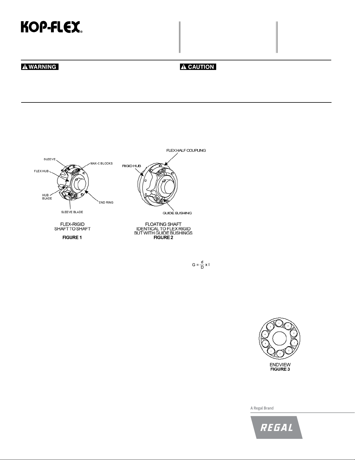
IDENTIFYING FEATURES
ASSEMBLY
These instructions apply specically to Couplings
described in KOP-FLEX Engineering Data Sheet 6015.
1. MOUNT FLEX & RIGID HUBS
a. Place an END RING over the shaft end on which
the ex half coupling is to be mounted. (Floating
shaft cou- plings will have guide bushings
installed in end ring.)
b. Clean the shaft and coat it with a suit- able anti-
galling lubricant, such as ANTI-SEIZE.
c. Expand HUB in oven until bore is substantially
larger than the shaft diameter. Straight bored
hubs are normally bored for an interference t
of approxi- mately 0.0005 in/in of shaft diameter.
(For most values of interference, this will require
a hub temperature of about 300°1). Install KEYS
with a tight t on sides and a slight clearance
over or under the key. Remove HUB from oven
and position quickly on shaft, with hub end ush
with shaft end.
Note: Ensure that the end ring end of the hub is
mounted away from the shaft end.
d. Taper Bored Hubs—
Micrometer Method: Calculate
where, G = Diametral Growth of hub body diameter
d = Diameter at small end of the bore
D = Hub body diameter.
(Actual measurement with an external
micrometer.)
I = Total Diametral Interference required.
Set micrometer to D + G. Draw hub onto shaft until
hub body diameter equals D + G, as checked with the
micrometer at 90° to keyway(s).
Draw Method: Mount the cold hub hand tight on the
shaft and tap lightly with a soft mallet to establish
initial snug t. Draw hub up an additional distance to
obtain the desired interference t for the connection.
(The required amount of axial movement is dependent
upon the bore diameter and taper angle.)
• Periodic inspections should be performed. Failure to perform proper maintenance
can result in premature product failure and personal injury.
Install the hub retention means provided with the shaft
and secure.
NOTE: Interference t requirements in excess of 0.0005
in/in of bore diameter should be referred to KOP- FLEX
for approval.
2. PLACE EQUIPMET IN POSITION Place SLEEVE
into position over FLEX HUB and move equipment
into place. Separate hubs by dimension ‘C’, Table A.
(For ywheel mounted assemblies, carefully guide
SLEEVE into rabbet in ywheel or adapter plate
and attach.) Install ange bolts and tighten to proper
installation torque.
3. ALIGN EQUIPMENT (See Fig. 4.) Attach END RING
to SLEEVE using caution in guiding rabbeted
diameter into place. Move equipment laterally and
jack or shim vertically until gap ‘X’ between the END
RING and the FLEX HUB is of uniform dimension
when measured with a feeler gage, and until surface
‘Y’ is ush with surface ‘Z’ when a straight edge is
placed across the two surfaces. (Where electric
motors, generators or thrust bearings are involved,
axial position of the rotor or bearing should be
controlled while positioning equipment.)
4. INSTALL MAX-C RESILIENT BLOCKS After the
equipment has been aligned as described above,
and with the end ring supported over the shaft, insert
the blocks in pairs using a nonmetallic hammer. See
end view of Figure 3 for proper installation sequences.
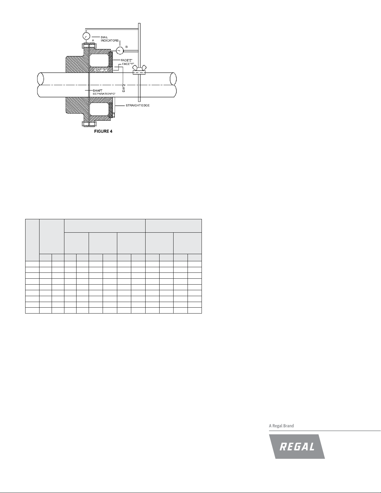
5. CHECK FINAL ALIGNMENT
Mount a dial indicator bracket on the ex half shaft with two dial indicators positioned
as shown in Figure 4. Rotating the drive slowly, take readings at four points 90°
apart and align as accurately as possible.
The two machines must be aligned within the tabulated values as shown in Table A.
Initial alignment should be as accurate as possible.
When alignment is completed, a nal check with a straight edge should be made
across the end ring and ex hub surfaces. If the difference exceeds the tabulated
value, adjustment should be made by moving one of the machines axially.
6. ATTACH END RING
Carefully guide END RING into rabbet in SLEEVE, install bolts and tighten to
proper installation torque. (END RING bolts to normally provided with Nylok
inserts. Bolts should be inspected to ensure that these inserts are intact prior
to attaching END RING.)
Maintenance
It is recommended that, during normal maintenance periods, the END
RING be removed and the MAX-C BLOCKS be examined for evidence of
cracking or splitting. The BLOCKS may also show some signs of permanent
deformation, but unless there are signs of deterioration or destruction of
the BLOCKS, this should not be considered cause for replacement. When
replacement of the BLOCKS becomes necessary, the procedure for removal
is the reverse of that described above for installation.
After removing the END RING, the BLOCKS can be levered out individually,
or the SLEEVE can be jacked away from the RIGID HUB after ange bolts
are removed, freeing all of the BLOCKS at once.
Once the BLOCKS have been removed, clean inner surfaces, insert new
BLOCKS if required, and re-install END RING in accordance with installation
instructions.
On oating shaft assemblies, the guide bushings can be replaced without
moving connected equipment — instructions are furnished with the
replacement bushings.
User Notice: The ratings of Kop-Flex’s Type ‘UB’ coupling were established
using the exceptional properties of the Kop-Flex MC elastomer. The use
of any other material can severely alter the coupling performance. If
replacement is ever necessary, the elastomer blocks must be replaced with
Kop-Flex MC elastomer blocks. Kop-Flex also manufacturesotherrubber
blocks for resilient couplings which are not intended for and should not be
used in Type ‘UB’ couplings.
TABLE A
ALLOWABLE INSTALLATION*
MISALIGNIMENT LIMITS
SHAFT
CPLG
SEP. “C”
SIZE
INCH MM INCH MM INCH MM INCH MM LB-FT N-m LB-FT N-m
1.5 3/32 2.381 .010 .254 .006 .152 .006 .152 13 17.6 6 8.13
2.0 3/32 2.381 .010 .254 .006 .152 .007 .178 23 31.2 13 17.63
2.5 1/8 3.175 .015 .381 .008 .203 .008 .203 23 31.2 23 31.20
3.0 1/8 3.175 .015 .381 .008 .203 .010 .254 23 31.2 35 47.50
3.5 1/8 3.175 .015 .381 .008 .203 .012 .305 55 74.6 55 74.60
4.0 1/8 3.175 .015 .381 .010 .254 .014 .356 55 74.6 110 149.20
5.0 1/8 3.175 .015 .381 .010 .254 .016 .406 11 0 149.2 200 271.20
6.0 3/16 4.763 .020 .508 .015 .381 .020 .508 200 271.2 320 433.90
7.0 3/16 4.763 .020 .508 .015 .381 .020 .508 200 271.2 320 433.90
* INITIAL INSTALLATION SHOULD BE ALIGNED AS ACCURATELY AS POSSIBLE
** MISMATCH BETWEEN END RING FACE “Z” AND FLEX HUB FACE “Y”
NOTE: CENTER FLANGE BOLTS HAVE SPECIAL BODY DIAMETERS FOR TIGHT
FIT IN THE JIG-REAMED BOLT HOLES— USE ONLY KOP-FLEX FURNISHED
BOLTS FOR REPLACEMENT
AXIAL**
±
RADIAL
(INDICATOR
“A”)FIGURE
4
ANGULAR
(INDICATOR
“B”)
±
BOLT TIGHTENING
TORQUE VALUES
CENTER
FLANGE
BOLTS
(SEE NOTE)
END RING
BOLTS
Kop-Flex, MAX-C are trademarks of Regal Beloit Corporation or one of its afliated companies.
©2015 Regal Beloit Corporation, All Rights Reserved. MCIM15129E • Form 6007CPE • Printed in USA
 Loading...