

Kop-Flex KD2, KD20 Installation Manual
KD2 & KD20 Disc Coupling
Installation and Alignment
Instructions
F O R M
15-111E
Revised
August 2015
• Read and follow all instructions carefully.
• Disconnect and lock-out power before installation and maintenance.
Working on or near energized equipment can result in severe injury or death.
• Do not operate equipment without guards in place. Exposed equipment can
result in severe injury or death.
1.0 General Instructions
Prior to installation, inspect the coupling for any signs of damage that may
have occurred during shipment. Check that all parts are on hand and are
as ordered.
Components should be cradled or supported during handling to avoid
damage and should be wrapped for protection. Flanges should be kept
free of nicks and burrs.
Read all of the installation instructions and review the procedure before
the actual coupling installation.
WARNING! Only bolts and nuts supplied by Kop-Flex are to be used.
2.0 Installation of Coupling Hubs - Keyed Mounting
2.1 Check the hub bore and shaft for nicks and burrs, dress if necessary. Make sure that the bore and shaft are clean.
2.2 For tapered bores, check the t of the bore to the shaft.
2.3 Keys must be precisely tted to the keyways in the shaft and hub.
Each key should have a tight t on the sides with a slight clearance
on top. To maintain dynamic balance, the keys should ll the keyways
exactly and not be too short or too long.
2.4 Clean the hub bore and shaft. For straight bores, proceed to step
2.6. For tapered bores, mount the hub hand-tight on the shaft and
lightly rap it with a soft mallet to establish the initial line-to-line t. This
is the START position. With a depth gauge, measure the amount the
hub overhangs the shaft end and record this value. See Figure 1.
• Periodic inspections should be performed. Failure to perform proper maintenance
can result in premature product failure and personal injury.
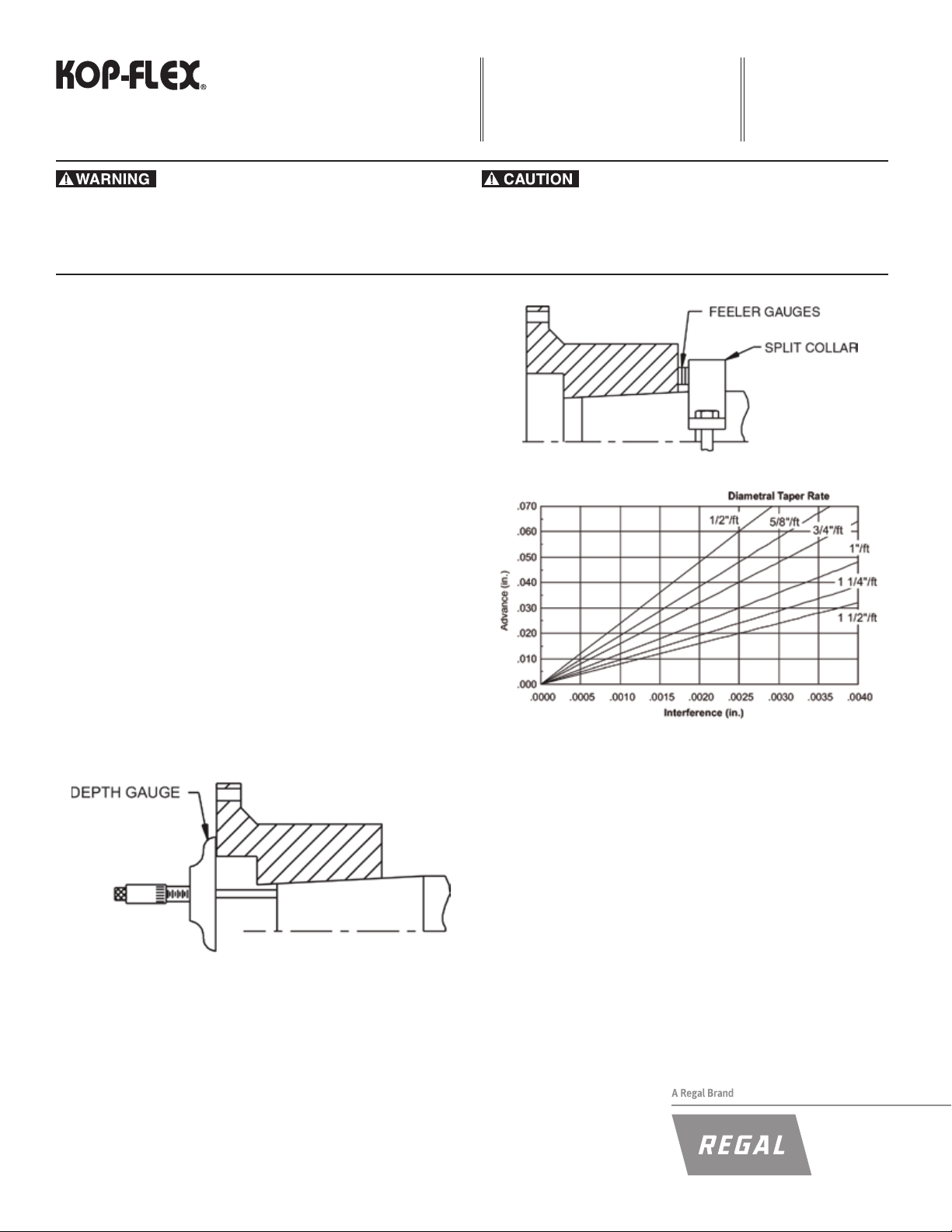
Figure 2. Using Split Collar to Set Advance
Figure 1. Measuring Hub Overhang
2.5 Tapered Bores Only: A recommended method to measure the hub
advance is to install a split collar on the shaft, away from the hub by
the amount of the speci ed advance. Use feeler gauges for accurate
spacing. See Figure 2. The amount of hub advance is dependent upon
the desired interference and taper angle as speci ed by the machine
manufacturer or as given on the coupling drawing. See Figure 3.
Figure 3. Hub Advance vs. Interference Chart
2.6 Heat the hub to expand the bore; DO NOT allow the hub tempera-
ture to exceed 600°F (300°C). DO NOT apply an open fl ame to any
part of the coupling, an oven is recommended.
WARNING! To avoid the risk of explosion, re, or damage to the coupling
and equipment, and/or injury to personnel, do not use an open fl ame or
oil bath to expand the hub. If heat is used at any time for installation, DO
NOT allow the hub temperature to exceed 600°F (300°C).
2.7 Place the hub in the proper position on the shaft. Hold the hub
in place as it cools. For tapered bores, verify the hub advance (see
Figures 1 and 2) and install the shaft retaining nut. Remove the split
collar from the shaft.
CENTER ASSEMBLY
WASHER
3.0 Alignment
Note: Exact values and procedures for aligning equipment are normally
speci ed by the equipment manufacturers. Good initial alignment to the
minimum possible values will promote optimum machinery performance
and eliminate potential operating problems. After securely tightening the
foundation bolts, the hub separation and alignment should be rechecked and
adjusted if necessary.
The coupling alignment should be checked periodically. Even when a
coupling is well aligned at installation, subsequent settling of foundations,
shifting of equipment, etc., may cause the alignment to deteriorate.
Offset and Angular Alignment
3.1 Reverse dial indication or optical methods of alignment (such as
laser) are recommended. A cold alignment and a hot check (with cor-
rections if necessary) are required. The hub fl ange OD can be used
to mount the alignment equipment. The hub fl ange OD is machined to
be concentric to the coupling bore and can be used as the reference
diameter.
3.2 The maximum recommended operating misalignment is:
0.10 degrees per disc pack
(0.0035 in/in TIR equivalent parallel offset)
Important: Total misalignment is the combination of equipment parallel
offset and angular misalignment.
Note that improving the alignment below these values will promote optimum machinery performance.
Axial Alignment
3.3 Align the hubs until they are at the correct hub separation. The hub
separation is measured from the two fl ange faces, not from the pilot face.
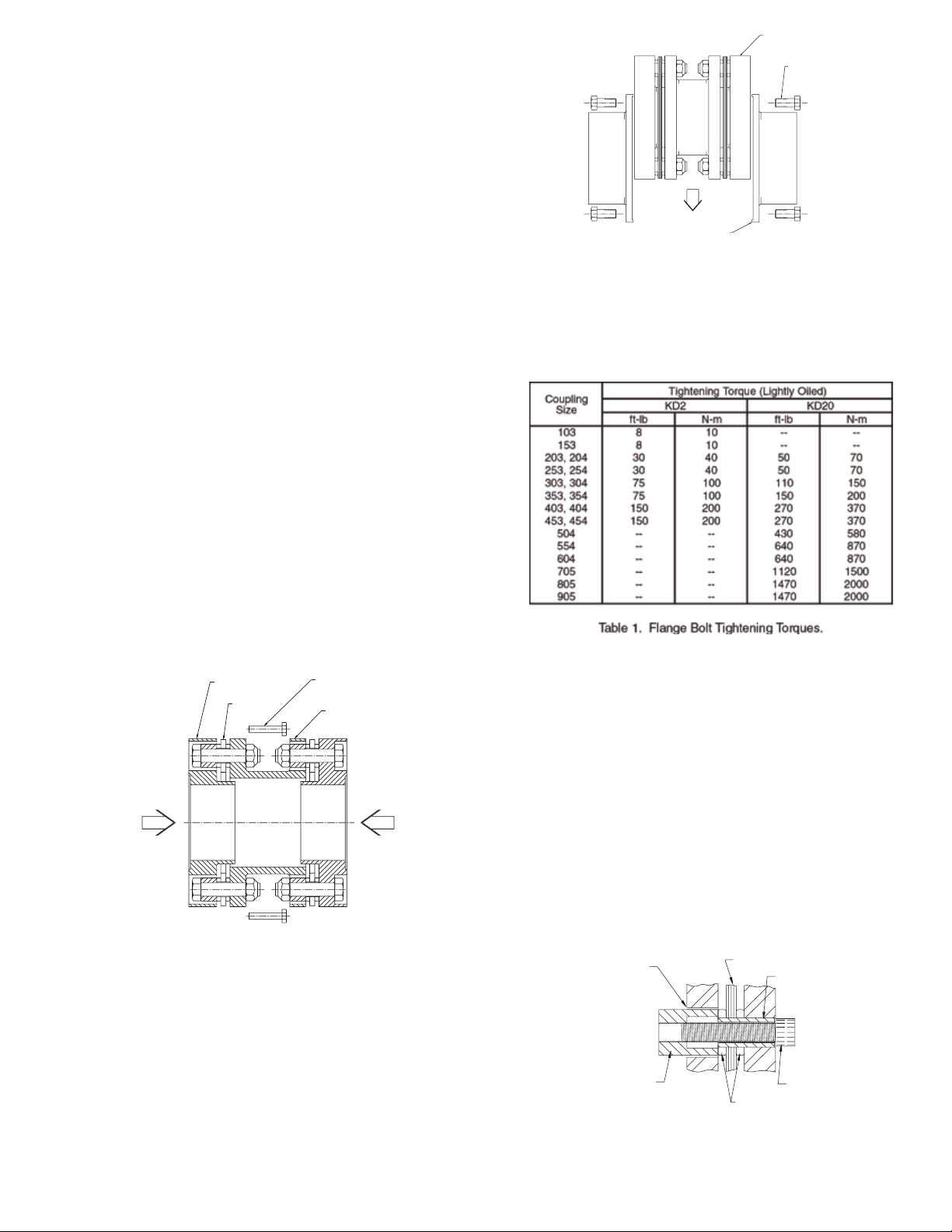
HUB BOLTS
O.D. PILOT
Figure 5. Installing center section
4.4 Put the center assembly (spacer and rings) between the rigid hubs,
engage the pilot, and install the hub bolts in one hub fl ange.
4.5 Release all the collapsing bolts, and install the hub fl ange bolts on
the second rigid hub fl ange.
4.6 Torque the hub fl ange bolts to the value speci ed in Table 1.
Hub Separation = Center Assembly Length
4.0 Final Assembly
(KD2 and KD20)
4.1 After correctly installing both hubs, use the separate collapsing
screws to pull the adapter rings toward the center of the pre-assembled
center section. This is made up of the spacer, two disc packs, and two
adapter rings.
ADAPTER RING
DISC PACK
Figure 4. Collapsing center section
4.2 For each side of the center section, insert the collapsing bolts through
the spacer clearance holes into tapped holes in the ring (see Figure 4).
4.3 Tighten them evenly and collapse the disc packs equally, only
enough to allow the center assembly to drop into place (see Figure 5).
COLLAPSING BOLT
SPACER
5.0 Removal
5.1 Disassemble the coupling in the reverse order as per the applicable
assembly procedure.
5.2 KEYED HUBS - Install a puller on the hub using the tapped holes
provided in the hub face. Pull the hub off the shaft.
6.0 Disc Pack Replacement
The terminology used to identify parts and the order of assembly may
differ from one coupling style to another. Follow the instructions which
match the coupling style being installed.
KD2 - For KD20 skip to 6.7
6.1 Remove the center assembly in reverse order as per the applicable
assembly procedure. Remove disc pack bolts and nuts.
6.2 Insert the disc pack removal socket into one of the clearance holes
in the spacer fl ange or ring (Figure 6). Install the removal cap screw and
turn it until it cannot be tightened any more.
Note: The removal socket is supplied as part of the “parts kit”.
CLEARANCE HOLE
REMOVAL SOCKET
DISC PACK
BUSHING
REMOVAL SCREW
Figure 6. Bolt Disc Pack to Adapter.
6.3 Remove the tool and repeat step 6.2 on all bushings to free the disc
pack from the ring and spacer.
 Loading...