

Installation and Alignment Instructions
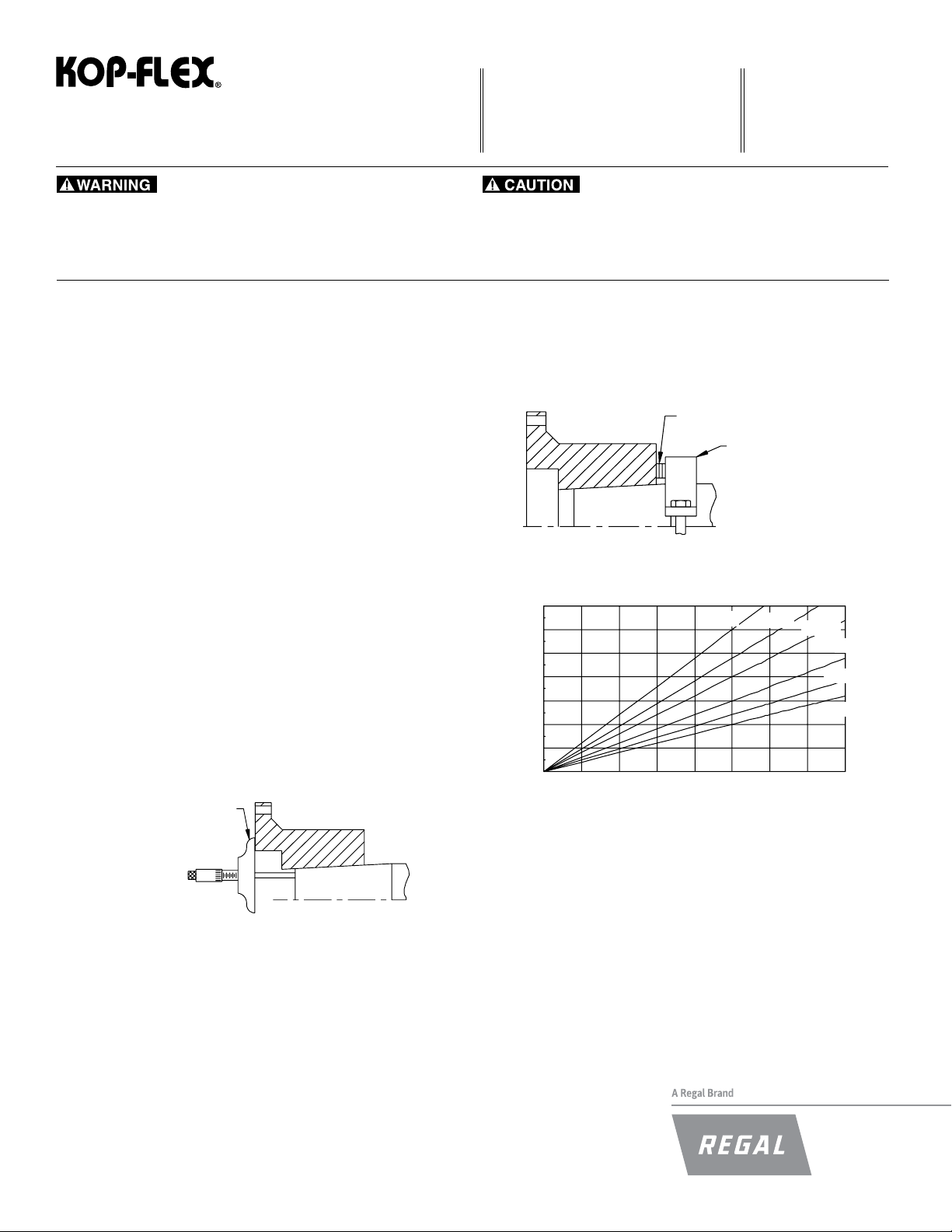
Figure 3. Hub Advance vs. Interference Chart
KD11 Disc Coupling
F O R M
22-002E
Revised
November 2015
• Read and follow all instructions carefully.
• Disconnect and lock-out power before installation and maintenance.
Working on or near energized equipment can result in severe injury or death.
• Do not operate equipment without guards in place. Exposed equipment can
result in severe injury or death.
WARNING! Because of the possible danger to person(s) or property from accidents which may result from the improper use or unapproved modication of the
product, this product must be installed, maintained, and operated in accordance with the procedures, standards and engineering information specied in
the product brochures and illustrations. To assure safe operation, this product should be inspected in accordance with the instructions described in this
form. Proper guards and other suitable safety devices or procedures as may be desirable, or as may be specied in safety codes, should be installed by
the user. Guards and other safety equipment are not provided, nor are they the responsibility of Regal Power Transmission.
• Periodic inspections should be performed. Failure to perform proper maintenance
can result in premature product failure and personal injury.
1. General Instructions
Prior to installation, inspect the coupling for any signs of damage that may have occured during shipping. Check that all parts are on hand and are as ordered.
WARNING! Only bolts and nuts supplied by Kop-Flex are to be used.
Components should be cradled or supported during handling to avoid damage and
should be wrapped for protection. Flanges should be kept free of nicks and burrs.
Read all of the installation instructions and review the procedure before the actual
coupling installation.
Figure 2. Using Split Collar to Set Advance
FEELER GAUGES
SPLIT COLLAR
2.0 Installation of Coupling Hubs - Keyed Mounting
2.1 Check the hub bore and shaft for nicks and burrs, dress if necessary.
Make sure that the bore and shaft are clean.
2.2 For tapered bores, check the t of the bore to the shaft.
2.3 Keys must be precisely tted to the keyway in the shaft and hub. Each
key should be a tight t on the sides with a slight clearance on top. To
maintain dynamic balance, the keys should ll the keyway exactly and
not be too short or too long.
2.4 Clean the hub bore and shaft. For straight bores, proceed to step 2.6.
For tapered bores, mount the hub hand-tight on the shaft and lightly rap
it with a soft mallet to establish the initial line-to-line t. This is the START
position. With a depth gauge, measure the amount the hub overhangs
the shaft end and record this value. See Figure 1.
DEPTH GAUGE
.070
.060
.050
).ni(ecnavdA
.040
.030
.020
.010
.000
.0000 .0005 .0010 .0015 .0020 .0025 .0030 .0035 .0040
Interference (in.)
Diametral Taper Rate
1/2"/ft
5/8"/ft
3/4"/ft
1"/ft
1 1/4"/ft
1 1/2"/ft
Figure 1. Measuring Hub Overhang
2.5 Taper Bores Only: A recommended method to measure the hub advance
is to install a split collar on the shaft, away from the hub by the amount
of the specied advance. Use feeler gauges for accurate spacing. See
Figure 2. The amount of hub advance is dependent upon the desired
interference and taper angle as specied by the machine manufacturer
or as given on the coupling drawing. See Figure 3.
2.6 Heat the hub to expand the bore; DO NOT allow the hub temperature to
exceed 600°F (300°C). DO NOT apply an open ame to any part of the
coupling, an oven is recommended.
WARNING! To avoid the risk of explosion, re, or damage to the cou-
pling and equipment, and/or injury to personel, do not use
an open ame or oil bath to expand the hub. If heat is used
at any time for installation, DO NOT allow the hub temperature to exceed 600°F (300°C).
2.7 Place the hub in the proper position on the shaft. Hold the hub in place
as it cools. For taper bores, verify the hub advance (see Figure 1 and 2)
and install the shaft retaining nut. Remove the split collar from the shaft.
3.0 Initial Assembly
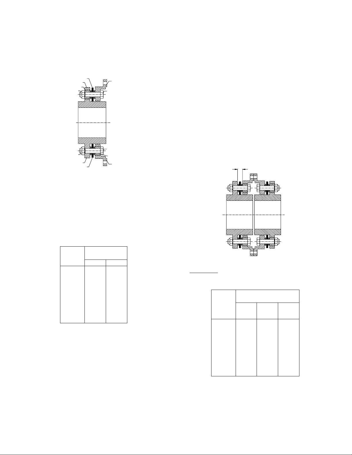
3.1 Place the disc pack and adapter in position over the hub body diameter
as shown in Figure 4. The reamed holes in the adapter should be
aligned with the large clearance holes in the hub as in the upper portion
of Figure 4. The large clearance holes in the adapter should be aligned
with the reamed holes in the hub as in the lower portion of Figure 4.
DISC PACK
SPACING WASHER
DISC PACK NUT
DISC PACK NUT
HUB
HUB
DISC PACK
Figure 4. Bolt Adapter and Disc Pack to Hub
3.2 Insert disc pack bolts through the reamed bolt holes in the adapter,
through the disc pack holes and through the clearance holes in the hub.
Install a spacing washer and nut over each disc pack bolt (See Figure
4., upper half). Place spacing washers on the remaining disc pack bolts
and insert them from the adapter side through the adapter clearance
holes, through the disc pack holes and through the reamed bolt holes in
the hub (See Figure 4., lower half).
ADAPTER
DISC PACK BOLT
DISC PACK BOLT
SPACING WASHER
ADAPTER
4.0 Alignment
Note: Exact values and procedures for aligning equipment are normally
specied by the equipment manufacturers.
The amounts given below represent values that would provide excel-
lent coupling performance in operation.
Good initial alignment to the minimum possible values will promote optimum machinery performance and eliminate potential operating problems. After securely tightening the foundation bolts, the hub separation
and alignment should be rechecked and adjusted if necessary. The
coupling alignment should be checked periodically. Even when a coupling is well aligned at installation, subsequent settling of foundations,
shifting of equipment, etc., may cause the alignment to deteriorate.
Axial Alignment
4.1 Measure the thickness of the disc pack before bringing the equipment
together. (See Figure 5 dimension P). The axial separation is set after
the adapters and disc packs are bolted to the hubs. Bring the driving
and driven equipment together until the anges of the adapters touch.
Measure the gap between the disc pack anges and adjust the axial
separation of the equipment until this measurement equals the thickness of the disc pack.
P
3.3 Tighten all nuts evenly and in an alternating fashion to the torque specied in Table 1.
Coupling
Size
103 10 14
153 27 37
204 55 75
254 55 75
304 115 160
354 175 240
404 280 380
454 280 380
504 420 570
554 730 1000
604 1020 1400
705 1800 2450
805 2300 3100
905 2300 3100
Disc Pack Bolt Tightening Torques
Tightening Torque
(Lightly Oiled)
ft-lb Nm
Table 1.
Figure 5. Axial Alignment Measurements
Reference only: The design hub separation for various hub arrangements
(Figure 6) is shown in Table 2.
Hub Separation (Inches)
Size
Standard
103 .12 1.31 2.50
153 .12 1.58 3.03
204 .12 1.62 3.12
254 .19 1.22 2.25
304 .19 1.41 2.62
354 .25 1.75 3.25
404 .25 2.25 4.25
454 .31 2.19 4.06
504 .31 2.20 4.09
554 .31 2.48 4.64
604 .31 2.70 5.09
705 .38 3.00 5.62
805 .38 3.53 6.68
905 .50 3.59 6.68
Design Hub Separations (Reference Only)
Reversed
Table 2.
One Hub
Two Hubs
Reversed
MCIM15114E • Form 22-002E • Printed in USA
2

HUB
SEPARATION
STANDARD
HUB
SEPARATION
ONE HUB REVERSED
5.0 Final Assembly
5.1 Bring the driving and driven equipment together until the anges of the
adapters just begin to touch. Measure the gap between the disc pack
anges and adjust the axial position of the equipment until the amount
of gap equals the disc pack thickness measured in step 4.1.
5.2 Rotate the equipment shafts until the ange holes are aligned.
5.3 Bolt the anges together using the ange bolts and nuts. See Figure 7.
Tighten all ange nuts evenly and in an alternating fashion to the torque
specied in Table 4.
HUB
SEPARATION
TWO HUBS REVERSED
Figure 6. Design Hub Separations
4.2 For some applications, initial set-up of the equipment may be simplied
by collapsing the disc packs slightly before bringing the equipment
together. KD11 couplings have been designed with collapsing holes for
this purpose. Collapsing screws are not supplied with the couplings.
See Table 3 for collapsing screw sizes.
Coupling Size
Collapsing Screw
Screw Size Length
103 1/4-20 UNC 1.00
153 1/4-20 UNC 1.25
204 1/4-20 UNC 1.50
254 1/4-20 UNC 1.50
304 1/4-20 UNC 1.75
354 3/8-16 UNC 2.25
404 3/8-16 UNC 2.50
454 3/8-16 UNC 2.50
504 1/2-13 UNC 3.00
554 1/2-13 UNC 3.25
604 5/8-11 UNC 3.50
705 1/2-13 UNC 4.00
805 5/8-11 UNC 4.50
905 5/8-11 UNC 4.50
Table 3. Collapsing Screw Sizes (not provided with coupling)
To collapse the disc packs, insert collapsing screws through the
clearance holes in the hub ange into the tapped holes in the adapter.
Tighten evenly to collapse the disc packs just enough to be able to position the equipment; usually .03” (sizes 103 through 404) and .06” (sizes
454 through 905) is sufcient. DO NOT OVERTIGHTEN.
Important: Remove collapsing screws and set axial alignment accord-
ing to 4.1. Do not operate coupling with collapsing screws installed.
Offset and Angular Alignment
4.3 Reverse dial indication or optical methods of alignment (such as laser)
are recommended. A cold alignment and a hot check (with corrections if
necessary) are required. The hub ange OD can be used to mount the
alignment equipment. The hub ange OD is machined to be concentric
to the coupling bore and can be used as the reference diameter.
4.4 The maximum recommended operating misalignment is:
0.10 degrees per disc pack
(0.0035 in/in TIR equivalent parallel offset)
Important:Total misalignment is the combination of equipment parallel
offset and angular misalignment.
Note that improving the alignment below these values will promote
optimum machinery performance.
Coupling
Size
103 9 12
153 9 12
204 9 12
254 18 24
304 18 24
354 25 34
404 25 34
454 60 81
504 60 81
554 120 160
604 120 160
705 120 160
805 210 285
905 335 450
Table 4. Flange Bolt Tightening Torque
Tightening Torque
(Lightly Oiled)
ft-lb N-m
Figure 7. Bolt Adapter
Flanges Together
6.0 Dynamic Balancing
Balanced parts will be marked with a letter “B”. The couplings may be
component balanced (hubs and adapters) with no match marks, or assembly
balanced as a complete coupling with matchmarks. If it is supplied with
matchmarks, it must be assembled with the matchmarks in line.
Note: For assembly balanced couplings, disconnecting the disc packs from
the hubs and adapters disturbs the balance of the coupling. When disc packs
are removed from assembly balanced couplings, the coupling assembly must
be rebalanced before placing back in operation.
7.0 Finish Boring and Keyways
Coupling hubs are often furnished with a “rough stock bore.” This rough bore
is not necessarily concentric to the other hub diameters. To prepare for boring, set-up and indicate the hub as shown in Figure 8.
8.0 Bore Sizing and Recommended Fits
The nish bore size should be based on the actual measured shaft dimension, regardless of whether it is a straight or tapered shaft. For keyed shafts,
a light interference t based on a nominal interfer- ence rate of 0.0005
inch per inch of shaft diameter is suggested, or refer to published AGMA
standards. Do not exceed an interference t 0.001 inch per inch of shaft
diameter. If other than a light interference t is desired, consult the published
AGMA boring and keyway standards.
For Straight Bores, the hub diameter should be chucked in the boring lathe
and dial indicated as shown in Figure 8.
For Taper Bores, chuck and indicate as shown in Figure 8. Machine the
counterbore and SKIM A REFERENCE DIAMETER on the hub body. Then,
reverse the hub in the chuck, and indicate using the reference diameter
before nal boring.
Run-outs should be as near zero as possible. It is essential that the nished
bores be concentric to the two indicating surfaces.
MCIM15114E • Form 22-002E • Printed in USA
3

9.0 Keyways
Keyways should be cut to give a tight t on the sides and a slight clearance
over the key. Keyways should not have sharp corners. Refer to published
AGMA standards for specic dimensioning of coupling bores and keyways.
OR
Figure 8. Hub Boring
Name (Last, First)
Title:
Company Name:
Location:
Phone:
APPLICATION DATA
10.0 General Recommendations
10.1 KOP-FLEX® KD11 disc couplings are designed to operate for extended
periods without the need for lubrication or maintenance. Visual inspection of the disc packs is sufcient to assess the operating condition of the
coupling.
10.2 All machinery should be monitored to detect unusual or changing vibration levels. The KOP-FLEX KD11 coupling, under normal operation
conditions, has no wearing parts and will retain its original balance quality. Any change in vibration levels should be investigated and remedial
action should be taken immediately.
5 YEAR WARRANTY REGISTRATION CARD
Coupling Type:
HP:
RPM:
Application:
Distance Between Shaft Ends
Send Warranty Card To: Attention Marketing Department
Kop-Flex, Inc.
Mail to: P. O. Box 1696 or Fax to: 410-787-8424
Baltimore, MD 21203-1696
:nevirD:gnivirD:)s(eziS tfahS
# rotoM# pmuP noitacifitnedI tnalP
Kop-Flex is a trademark of Regal Beloit Corporation or one of its afliated companies.
©2015 Regal Beloit Corporation, All Rights Reserved. MCIM15114E • Form 22-002E • Printed in USA
 Loading...