

KD1 and KD10 Disc Coupling
Installation and Alignment
Instructions
F O R M
22-001E
Revised
August 2015
• Read and follow all instructions carefully.
• Disconnect and lock-out power before installation and maintenance.
Working on or near energized equipment can result in severe injury or death.
• Do not operate equipment without guards in place. Exposed equipment can
result in severe injury or death.
1.0 General Instructions
Prior to installation, inspect the coupling for any signs of damage
that may have occurred during shipment. Check that all parts
are on hand and are as ordered. Components should be cradled
or supported during handling to avoid damage and should be
wrapped for protection. Flanges should be kept free of nicks and
burrs. Read all of the installation instructions and review the procedure before the actual coupling installation.
WARNING! Only bolts and nuts supplied by Kop-Flex are to be used.
2.0 Installation of Coupling Hubs - Keyed Mounting
Make sure the base of the housing and the support surfaces are
clean and free from burrs. If the housing elevation is adjusted with
shims these must cover the entire contact area between the housing and the support surface.
2.1 Check the hub bore and shaft for nicks and burrs, dress if
necessary. Make sure that the bore and shaft are clean.
2.2 For tapered bores, check the t of the bore to the shaft.
2.3 Keys must be precisely tted to the keyways in the shaft
and hub. Each key should have a tight t on the sides with a
slight clearance on top. To maintain dynamic balance, the keys
should ll the keyways exactly and not be too short or too long.
• Periodic inspections should be performed. Failure to perform proper maintenance
can result in premature product failure and personal injury.
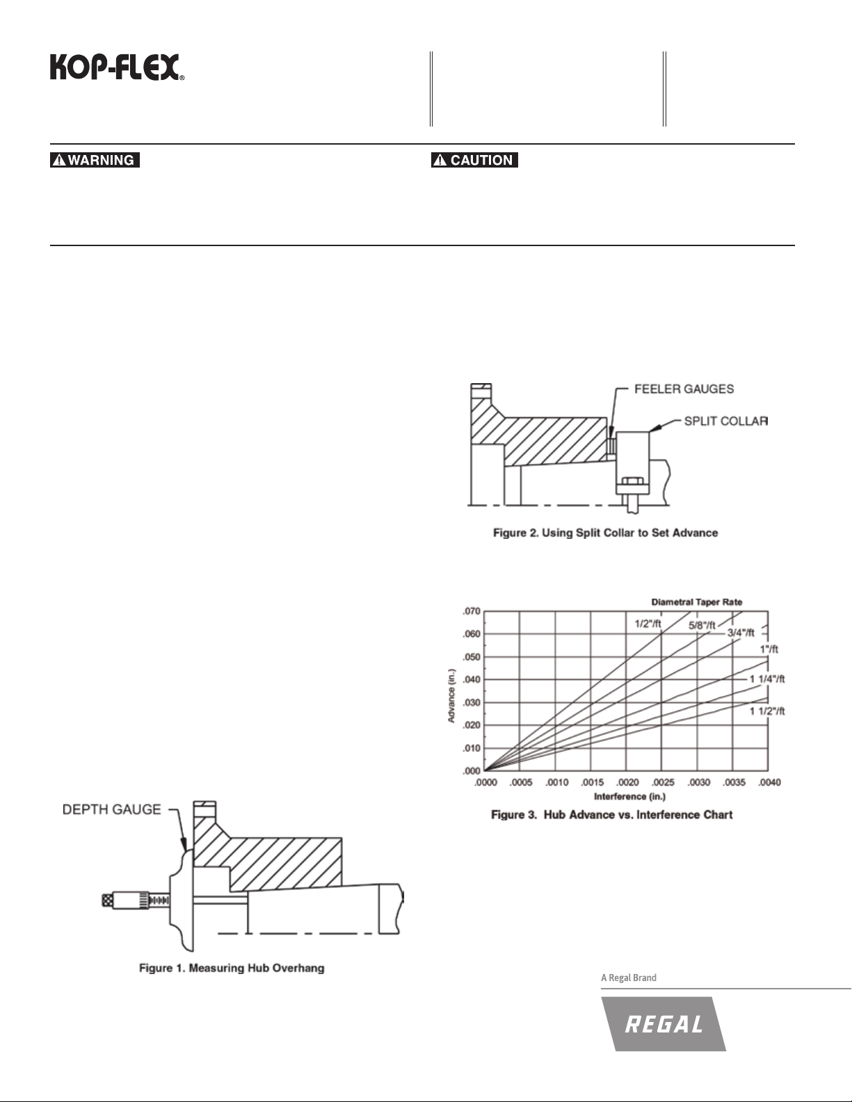
2.5 Tapered Bores Only: A recommended method to measure
the hub advance is to install a split collar on the shaft, away
from the hub by the amount of the speci ed advance. Use
feeler gauges for accurate spacing. See Figure 2. The amount
of hub advance is dependent upon the desired interference
and taper angle as speci ed by the machine manufacturer or
as given on the coupling drawing. See Figure 3.
2.4 Clean the hub bore and shaft. For straight bores, proceed
to step 2.6. For tapered bores, mount the hub hand-tight on
the shaft and lightly rap it with a soft mallet to establish the
initial line-to-line t. This is the START position. With a depth
gauge, measure the amount the hub overhangs the shaft end
and record this value. See Figure 1.
2.6 Heat the hub to expand the bore; DO NOT allow the hub
temperature to exceed 600°F (300°C). DO NOT apply an open
fl ame to any part of the coupling, an oven is recommended.
2.7 Place the hub in the proper position on the shaft. Hold the
hub in place as it cools. For tapered bores, verify the hub advance (see Figures 1 and 2) and install the shaft retaining nut.
Remove the split collar from the shaft.
3.0 Initial Assembly
The terminology used to identify parts and the order of assembly
may differ from one coupling style to another. Follow the instructions
which match the coupling style being installed.
KD1 - For KD10 skip to 3.5
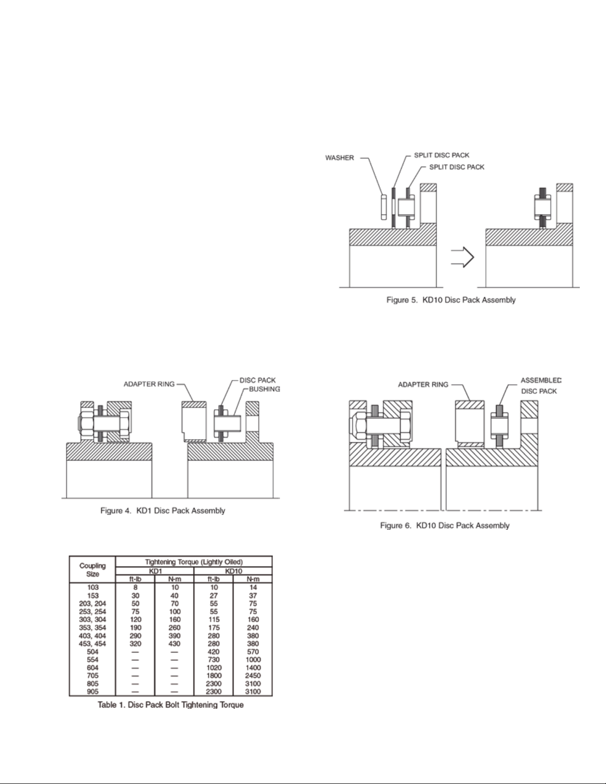
3.1 Line up the disc pack bushings with the reamed holes in
the hub. Lightly tap on the bushings to start them in the reamed
holes (See Figure 4).
3.2 Insert three disc pack bolts from the disc pack side, through
the three bushings that are lightly tapped into the reamed holes.
Assemble with lock-nuts and tighten them evenly and in successive steps until they are tightened to the speci ed value in Table
1.
3.3 Position the adapter ring over the hub so that the spacer pilot
and counterbored holes are on the face opposite the disc pack.
(see Figure 4).
3.4 Install the disc pack bolts and nuts with the bolt heads in the
ring. Torque the fasteners evenly and in successive steps to the
values in Table 1.
KD10 - For KD1 skip to 4.0
3.5 The disc packs are packaged as two halves; one left hand
(yellow mark) and one right hand pack (white mark). One left half
and one right half must be put together to make one complete
disc pack. For replacements, slide one half through the gap
between the hubs followed by the other half.
3.6 Place the two halves on the hub, press together and reassemble the complete disc pack (see Figure 5).
3.7 Position the adapter ring over the hub so that the spacer pilot
and counterbored holes are on the face opposite the disc pack.
(see Figure 6). Make sure to align reamed holes with larger
clearance holes in mating part.
3.8 Install the disc pack bolts and nuts with the bolt heads in the
ring. Torque all disc pack bolts to the values speci ed in Table 1.
4.0 Alignment
Note:Exact values and procedures for aligning equipment are nor-
mally speci ed by the equipment manufacturers.
The amounts given below represent values that would provide excellent coupling performance in operation.
Good initial alignment to the minimum possible values will promote
optimum machinery performance and eliminate potential operat-
ing problems. After securely tightening the foundation bolts, the
hub separation and alignment should be rechecked and adjusted if
necessary.
The coupling alignment should be checked periodically. Even when
a coupling is well aligned at installation, subsequent settling of
foundations, shifting of equipment, etc., may cause the alignment to
deteriorate.

Offset and Angular Misalignment
4.1 Reverse dial indication or optical methods of alignment (such
as laser) are recommended. A cold alignment and a hot check
(with corrections if necessary) are required. The hub fl ange
OD can be used to mount the alignment equipment. The hub
fl ange OD is machined to be concentric to the coupling bore and
can be used as the reference diameter.
4.2 The maximum recommended operating misalignment is:
0.10 degrees per disc pack (0.0035 in/in TIR equivalent parallel
offset)
Important: Total misalignment is the combination of equipment
parallel offset and angular misalignment. Note that improving the
alignment below these values will promote optimum machinery
performance.
Axial Alignment
4.3 Align the hubs until they are at the hub separation used in
Table 2, or as shown on the coupling drawing if one is supplied.
6.0 Disc Pack Replacement
KD1 - For KD10 Skip to 6.8
6.1 Remove the spacer halves in reverse order as per the applicable assembly procedure. Once these are removed work on
one hub at a time.
6.2 Loosen and remove all of the disc pack bolts from the half
coupling.
6.3 Insert the disc pack removal socket into one of the disc pack
clearance holes as shown in Figure 8 (counter bore rst), install
the removal capscrew and turn it until it cannot be tightened any
more.
Note: The removal socket is supplied as part of the “parts kit”.
5.0 Final Assembly (KD1 and KD10)
5.1 Insert the collapsing bolts into the hub thru holes and thread
into the ring. Draw the rings towards the hub fl anges by tightening the collapsing bolts. Collapse ONLY ENOUGH to enable the
split spacer to t between the rings. See Figure 7.
5.2 Insert one of the spacer halves between the two rings.
Thread bolts in by hand.
5.3 Repeat for the other spacer half, making sure that the fl ange
OD groove in the two spacer halves match. IMPORTANT: Re-
move the bolts used to collapse the disc pack. Tighten all spacer
bolts evenly and in an alternating fashion as speci ed in Table 3.
6.4 Repeat step 6.3 on all of the bushings to free the disc pack
from the ring and hub fl ange.
6.5 Slide the ring and disc pack out of the coupling from between
the hubs. Repeat steps 6.3 to 6.4 to remove the second disc
pack.
6.6 Clean and deburr all the coupling parts.
6.7 Install new disc packs per 3.1 to 3.4.
KD10
6.8 Remove the spacer halves in reverse order as per the ap-
plicable assembly procedure. Once these are removed work on
one hub at a time.
6.9 Unbolt the adapter ring and slide it out of the way onto the
other hub. Unbolt the disc pack from the hub and pull the wash-
ers off using pliers.
6.10 Split the disc pack into two separate halves. Remove each
disc pack half through the gap between the hubs.
6.11 Install new disc packs per 3.5 to 3.8.
7.0 Dynamic Balance
Balanced parts will be marked with the letter “B.”. A standard
balanced coupling will not have match marks. If a coupling is
supplied with match marks, it has been specially balanced; the
coupling must be assembled with the match marks in line.
8.0 Finish Boring and Keyways
Coupling hubs are often furnished with a “rough stock bore.” This
rough bore is not necessarily concentric to other hub diameters. To
prepare for boring, set-up and indicate the hub as shown in Figure 9.

9.0 Bore Sizing and Recommended Fit
The nish bore size should be based on the actual measured
shaft dimension, regardless of whether straight or taper shaft.
For keyed shafts, a light interference t based on a nominal interference rate of 0.0005 inch per inch of shaft diameter is sug-
gested, or refer to published AGMA standards. Do not exceed
an interference t of 0.001 inch/inch of shaft diameter. If other
than a light interference t is desired, consult the published
AGMA boring and keyway standards.
For Straight Bores, the hub diameter should be chucked in
the boring lathe and dial indicated as shown of Figure 9.
For Taper Bores, chuck and indicate as shown on Figure 9.
Machine the counterbore and SKIM A REFERENCE
DIAMETER on the hub body. Then, reverse the hub in the
chuck, and indicate using the reference diameter before nal
boring. Run-outs should be as near zero as possible. It is
essential that the nished bore be concentric with the two
indicating surfaces.
10.0 Keyways
Keyways should be cut to give a tight t on the sides and
slight clearance over the key. Keyways should not have sharp
corners. Refer to published AGMA standards for specic
dimensioning of coupling bores and keyways.
11.0 General Recommendations
11.1 KOP-FLEX KD1 and KD10 split spacer style disc
couplings are designed to operate for extended periods
without the need for lubrication or maintenance. Visual
inspection of the disc packs is sufcient to assess the
operational condition of the coupling.
11.2 All machinery should be monitored to detect unusual or
changing vibration levels. KOP-FLEX KD1 and KD10 split
spacer style couplings, under normal operation conditions,
have no wearing parts and will retain their original balance
quality. Any change in vibration levels should be investigated
and remedial action should be taken immediately.
5 YEAR WARRANTY REGISTRATION CARD
Name (Last, First) _______________________________________________________________________________________
Title: _________________________________________________________________________________________________
Company Name: ________________________________________________________________________________________
Location: ______________________________________________________________________________________________
Phone: ________________________________________________________________________________________________
APPLICATION DATA
Coupling Type: __________________________________________________________________________________________
HP: _________________________________________________________________________________________________
RPM: _________________________________________________________________________________________________
Application: ____________________________________________________________________________________________
Shaft Size(s): Driving:____________ Driven:_____________
Distance Between Shaft Ends ______________________________________________________________________________
Plant Identication Pump #____________ Motor #_____________
Send Warranty Card To: Attention Marketing Department
Kop-Flex, Inc.
Mail to: P. O. Box 1696 or Fax to: 410-787-8424
Baltimore, MD 21203-1696
Kop-Flex is a trademark of Regal Beloit Corporation or one of its afliated companies.
©2015 Regal Beloit Corporation, All Rights Reser ved. MCIM15038E • Form 22-001E • Printed in USA
 Loading...