

Refrigeration System
Specications
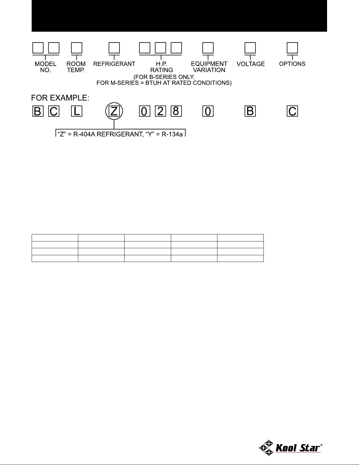
Kool Star Refrigeration Nomenclature
MODEL NUMBER EXPLANATION (CONVENTIONAL = ACCESSIBLE HERMETIC )
BC = Built-up Remote Conventional Condensing Unit MH = Hermetic Condensing Unit
BH = Built-up Remote Hermetic Condensing Unit MS = Scroll Condensing Unit
BS = Built-up Remote Scroll Condensing Unit MD = Discus Condensing Unit
MC = Semi-hermetic Condensing Unit
ROOM TEMPERATURE EXPLANATION
H = +25° through +70° F. Room Temperature
L = 0° F. through -20° F. Room Temperature
HORSEPOWER RATING EXPLANATION (NOTE: APPLIES TO B-SERIES ONLY)
028 = 3 H.P. 050 = 5 H.P. 100 = 10 H.P. 220 = 22 H.P. 350 = 35 H.P.
030 = 3 H.P. 060 = 6 H.P. 120 = 12 H.P. 250 = 25 H.P. 400 = 40 H.P.
035 = 31/2 H.P. 075 = 71/2 H.P. 150 = 15 H.P. 270 = 27 H.P.
040 = 4 H.P. 090 = 9 H.P. 200 = 20 H.P. 300 = 30 H.P.
BTU/HR RATING EXPLANATION (NOTE: APPLIES TO M-SERIES ONLY)
Room temp H = Nominal BTUH capacity @ 30° suction, 90° ambient (1000 multiplier)
Room temp L = Nominal BTUH capacity @-20° suction, 90° ambient (1000 multiplier)
EQUIPMENT VARIATION EXPLANATION
0 = Standard W = Water Cooled
A = Plasma Units X = Special Applications
D = Demand Cooling Y = Special Applications
L = Large Condenser
VOLTAGE EXPLANATION
A = 115/60/1 F = 200-220/50/3
B = 230/60/1 or 208-230/60/1 (As Applicable) G = 380-420/50/3
C = 208-230/60/3 H = 208/60/1
D = 460/60/1 J = 380/50/1
E = 460/60/3 K = 200-220/50/1 or 220/50/1
OPTIONS EXPLANATION (NOTE: APPLIES TO B-SERIES ONLY)
C = Coated Condenser Coil
D = Coated Condenser Coil, Heated And Insulated Receiver
L = Large Condenser
888-478-8600 • FAX: 310-513-8156
Specications subject to change without notice.

Contents
Evaporator Coils For Remote Systems ...............................................................................................................2
B-Series Built-Up Condensing Units ..................................................................................................................3
B-Series Medium Temperature Specications ....................................................................................................4
B-Series Low Temperature Specications ...........................................................................................................6
B-Series Components .........................................................................................................................................8
M-Series High Ambient Remote Condensing Units ..........................................................................................9
M-Series Medium Temperature Specications .................................................................................................10
M-Series Low Temperature Specications ........................................................................................................14
M-Series Components ......................................................................................................................................16
DRS Series Dual Compressor Systems ..............................................................................................................15
Condensing Unit Base Specications ..............................................................................................................18
PRS-2 Packaged Refrigeration Systems .............................................................................................................21
PRS-2 Packaged Refrigeration System Specications .......................................................................................22
As we are continuously improving and enhancing our products to benet our customers, we reserve the
right to change pricing and specications without notice.
888-478-8600 • FAX: 310-513-8156
Specications subject to change without notice.
1
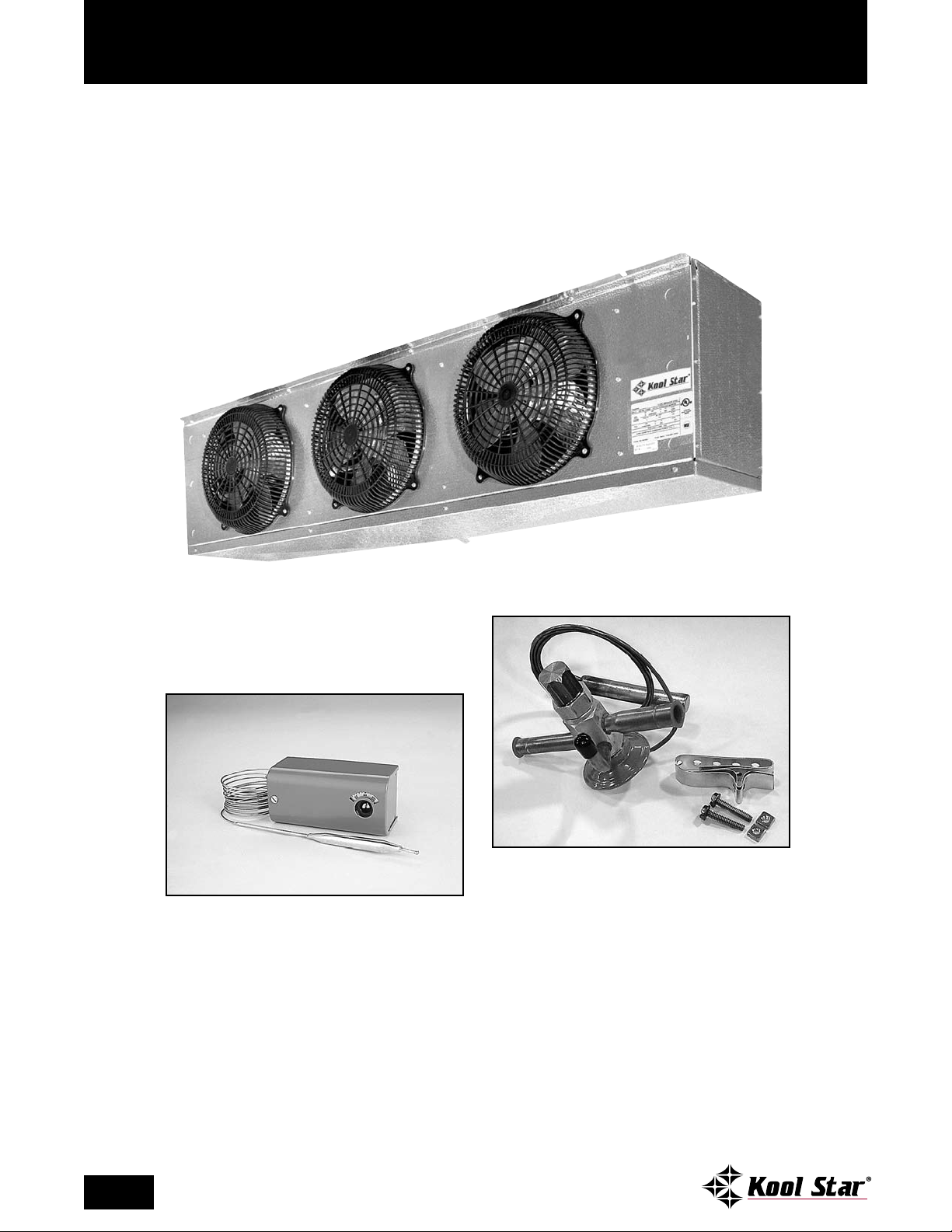
Evaporator Coils For Remote Systems
-series evaporator coils are ready to mount
E
in position and are available in either air (off
cycle) or electric defrost. Each is also furnished
standard with a properly sized expansion valve and
room thermostat. Electric defrost models feature
defrost termination-fan delay controls and drain
line heaters.
STANDARD EXPANSION VALVE
STANDARD TEMPERATURE CONTROL/ROOM
THERMOSTAT
2
888-478-8600 • FAX: 310-513-8156
Specications subject to change without notice.
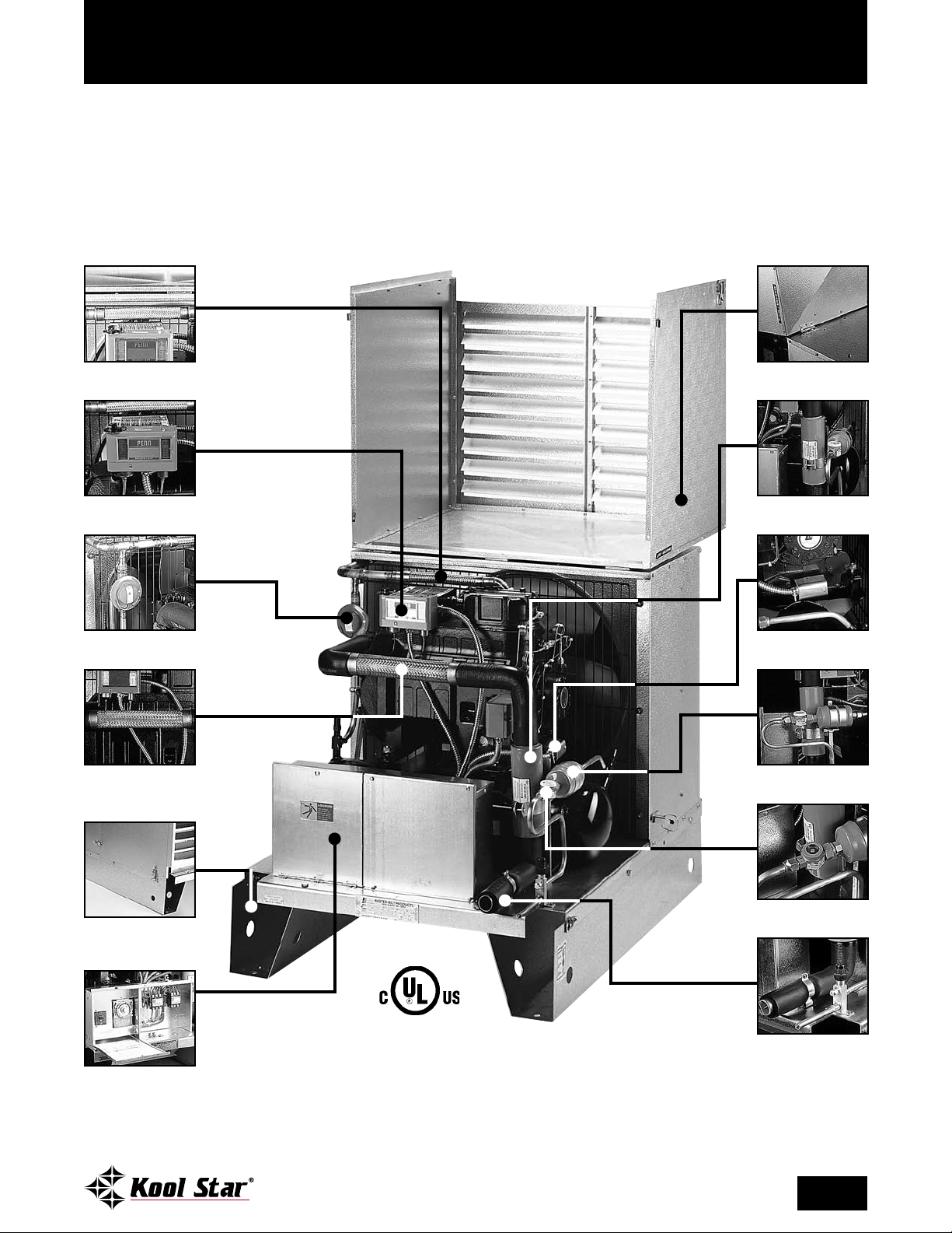
B-Series Built-Up Condensing Units
ool Star offers one of the most complete
K
condensing units in the built-up B-Series.
These units are completely factory assembled on
a galvanized steel base. Accessories are pre-wired
and mounted, resulting in minimal eld installation time. All that is required is electrical hookup,
LIQUID LINE VIBRATION ABSORBER
(SEMI-HERMETIC ONLY)
ADJUSTABLE
DUAL PRESSURE CONTROL
piping, connection, evacuation, leak testing and
charging to become operational.
B-Series systems are available in hermetic, semihermetic and compliant scroll compressor models
and range from 3 H.P. to 40 H.P.
SNAP-DOWN HINGED
WEATHER HOOD
SUCTION LINE
FILTER
HEAD PRESSURE CONTROL
(FLOODING VALVE)
SUCTION LINE VIBRATION
ABSORBER
(SEMI-HERMETIC ONLY)
HEAVY-DUTY CHANNEL
LEG BASE WITH
LOCKABLE HOOD
PRE-WIRED ELECTRICAL
CONTROL PANEL WITH
TIMER AND CIRCUIT
BREAKER OR
FUSE BLOCK
CRANKCASE
HEATER
LIQUID LINE
FILTER/DRIER
SIGHT GLASS
LIQUID & SUCTION
LINE KIT WITH
SERVICE VALVE
Above components pictured are typical with the model BCLZ0300C condensing unit. Components may vary
depending on horsepower and application. Consult factory for verication of standard and optional supplied components.
888-478-8600 • FAX: 310-513-8156
Specications subject to change without notice.
3
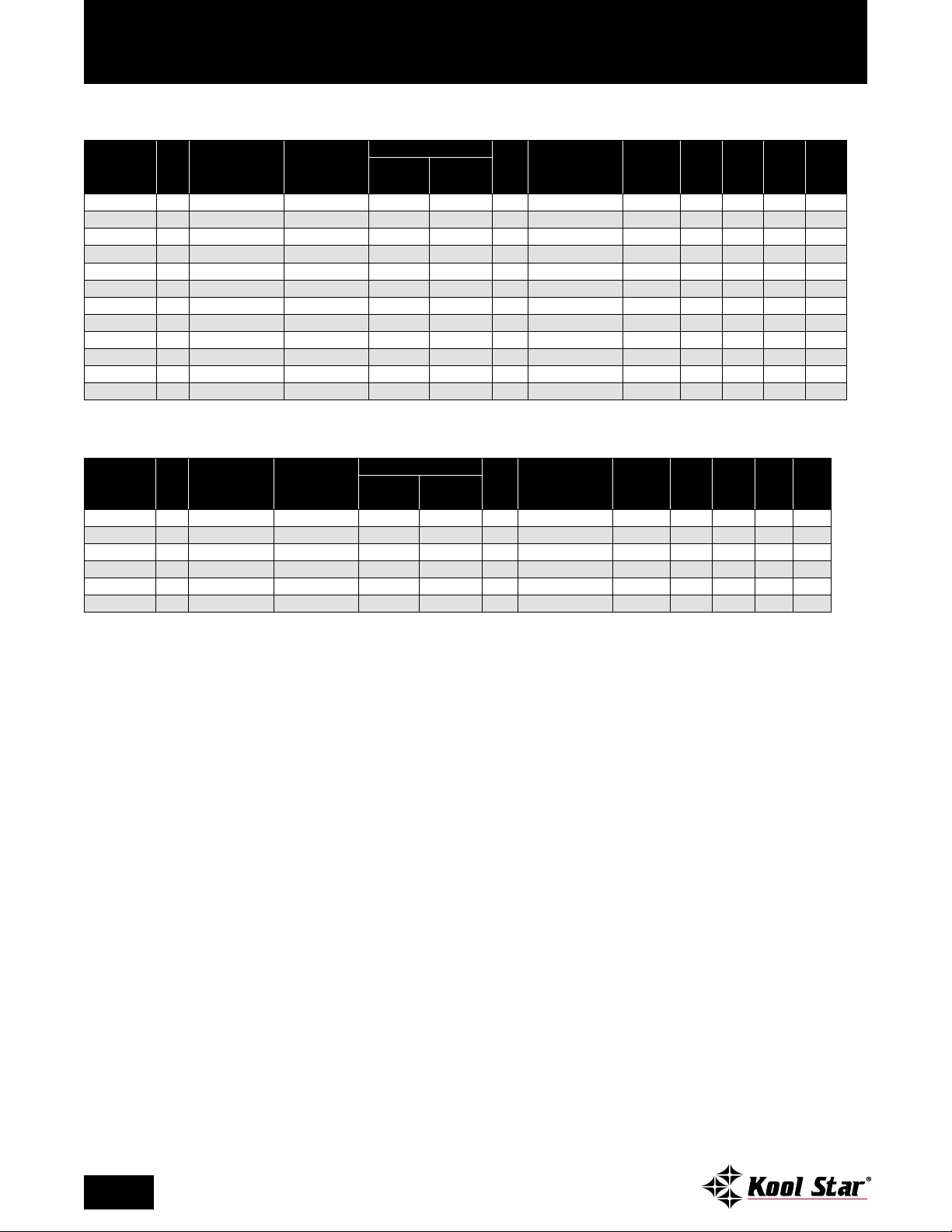
B-Series Medium Temperature Specications
R-404A SEMI-HERMETIC CONDENSING UNITS
UNIT CONNECTION SIZES
LIQUID SUCTION
BASE
RECEIVER PUMP
†
SIZE
DOWN CAP. @ 90%
SHIP WT.
(LB/KG) MCA
††
MOP††RLA††LRA
††
COND. UNIT
MODEL* H.P.
COMPRESSOR
MODEL
BTUH @ 25°F
SUCTION TEMP.
90°F AMBIENT
BCHZ0200C 2 ERCA-021E-TAC 17,402 1/2 7/8 C 25.6 450/205 15 20 8.8 46
BCHZ0300C 3 ERFA-031E-TAC 24,604 5/8 1-1/8 C 41.5 580/264 19 30 12.4 82
3
/
BCHZ0500C 5 2DC3R53KE-TFC 42,078 5/8 1
BCHZ0750C 7.5 2DA3R89KE-TFC 72,419 5/8 1
BCHZ1000C 10 3DB3R12ME-TFC 103,018 7/8 1
BCHZ1200C 12 3DF3R15ME-TFC 121,728 7/8 1
BCHZ1500C 15 3DS3R17ME-TFC 131,837 7/8 1
3
BCHZ2000C 20 4DA3R18ME-TSK 161,134 1
BCHZ2500C 25 4DH3R22ME-TSK 199,216 1
BCHZ3000C 30 4DJ3R28ME-TSK 243,058 1
BCHZ3500C 35 6DH3R35ME-TSK 295,141 1
BCHZ4000C 40 6DJ3R40ME-TSN 406,681 1
/
8
3
/
8
3
/
8
5
/
8
5
/
8
3
3
3
5
21/
21/
21/
21/
21/
C 41.5 600/273 34 50 22.3 120
8
/
E 80.8 870/395 47 70 32 169
8
/
F 116.1 990/450 64 100 43.6 215
8
/
F 116.1 990/450 70 100 48.1 275
8
/
F 116.1 1010/459 84 125 59.6 275
8
P 116.1 1710/777 88 125 58.7 308
8
P 116.1 1730/786 107 175 74.4 428
8
R 116.1 1740/791 127 200 84 470
8
R 157.1 1810/823 178 300 125.1 565
8
R 157.1 1940/882 164 275 113.4 594
8
R-404A HERMETIC CONDENSING UNITS
BTUH @ 25°F
COND. UNIT
MODEL* H.P.
COMPRESSOR
MODEL
SUCTION TEMP.
90°F AMBIENT
BHHZ0300B 3 CS20K6E-PFV 26,396 1/2 7/8 C 41.5 405/184 27 40 18.6 96.0
BHHZ0300C 3 CS20K6E-TF5 26,396 1/2 7/8 C 41.5 405/184 18 25 11.4 75.0
BHHZ0400B 4 CS27K3E-PFV 32,827 5/8 7/8 C 41.5 510/232 34 50 23.9 95.4
BHHZ0400C 4 CS27K3E-TF5 32,827 5/8 7/8 C 41.5 510/232 24 35 15.6 82.0
BHHZ0500B 5 CS33K3E-PFV 37,373 5/8 7/8 C 41.5 520/236 42 70 30.7 125.0
BHHZ0500C 5 CS33K3E-TF5 37,373 5/8 7/8 C 41.5 520/236 30 45 20.7 90.0
NOTES:
• Consult factory for R-134a applications.
• Semi-hermetic medium temp units are shipped with P.O.E. oil, which is compatible with optional refrigerants (contact factory for details).
*VOLTAGE KEY:
“B” sufx = 208-230 or 230 volt, 60 cycle, one phase
“C” sufx = 200-230 or 208-230 volt, 60 cycle, three phase
†
See pp. 20-22 for unit base drawings.
††
Electrical ratings for condensing unit only. See National Electrical Code if units are combined on a single circuit.
UNIT CONNECTION SIZES
LIQUID SUCTION
BASE
RECEIVER PUMP
†
SIZE
DOWN CAP. @ 90%
SHIP WT.
(LB/KG) MCA
††
MOP††RLA††LRA
††
4
888-478-8600 • FAX: 310-513-8156
Specications subject to change without notice.
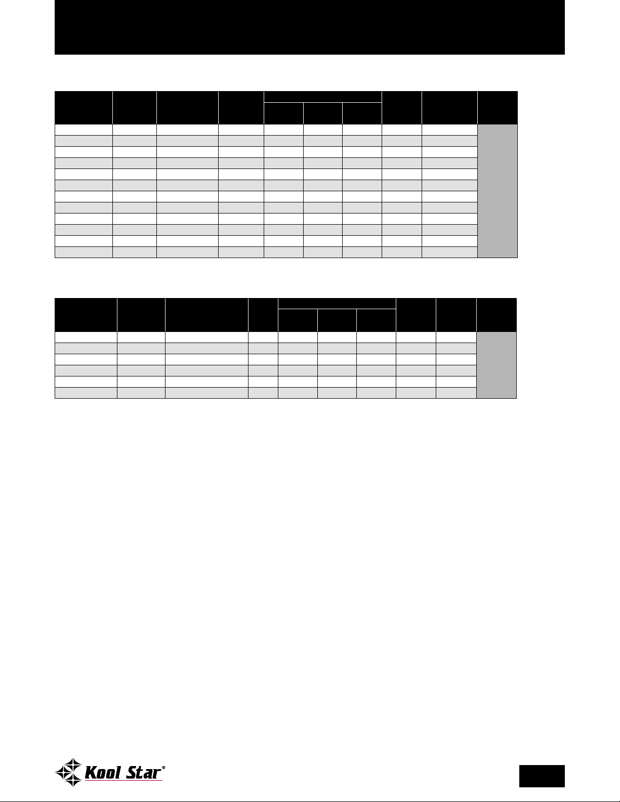
B-Series Medium Temperature Specications
MATCHING EVAPORATOR COILS FOR R-404A SEMI-HERMETIC CONDENSING UNITS
EVAPORATOR
MODEL*
E1HZ0156A SA38-160 16,000 3 64 15 16 110/50 2.7
E1HZ0245A IFA36-240A 24,000 4 76 19 19 290/132 3.6
E1HZ0365A IFA26-370A 37000 2 76 20 25 360/118 6
E1HZ0365A(2)
E1HZ1100C PAM4-1100 110,000 4 137 30 51 830/377 13.8
E1HZ1100C PAM4-1100 110,000 4 137 30 51 830/377 13.8
E1HZ1400C PAM4-1320 132,000 4 137 30 51 885/402 13.8
E1HZ0450A(3)
E1HZ1100C(2)
E1HZ1100C(2)
E1HZ1100C(3)
E1HZ1100C(4)
UNIT
PART NO.
††
IFA26-370 74,000 4 (total) 76 20 25 360/164 12 (total)
††
IFA36-460 147,000 9 (total) 106 20 25 415/189 27 (total)
††
PAM4-1100 220,000 8 (total) 137 30 51 830/377 27.6 (total)
††
PAM4-1100 220,000 8 (total) 137 30 51 830/377 27.6 (total)
††
PAM4-1100 330,000 12 (total) 137 30 51 830/377 41.4 (total)
††
PAM4-1100 440,000 16 (total) 137 30 51 830/377 55.2 (total)
BTUH @
SUCTION TEMP.
25°F**
NO.
FANS
DIMENSIONS (INCHES)
MATCHING EVAPORATOR COILS FOR R-404A HERMETIC CONDENSING UNITS
EVAPORATOR
MODEL*
E1HZ0245A IFA36-240A 24,000 4 76 19 19 290/132 3.6
E1HZ0245A IFA36-240A 24,000 4 76 19 19 290/132 3.6
E1HZ0300A IFA36-305 30,500 3 76 19 19 320/145 3.6
E1HZ0300B IFA36-305 30,500 3 76 19 19 320/145 1.8
E1HZ0365A IFA26-370 37,000 2 76 20 25 360/164 6
E1HZ0365B IFA26-370 37,000 2 76 20 25 360/164 4.2
*VOLTAGE KEY:
“A” sufx = 115 volt, 60 cycle, one phase
“B” sufx = 208-230 volt, 60 cycle, one phase
“C” sufx = 208-230 volt, 60 cycle, three phase
**Based on 10° T.D.
†
Dimensions, weights and amps are per evaporator.
††
Evaporator models followed by a number in parentheses indicates that multiple coils are necessary.
UNIT
PART NO.
BTUH @
SUCTION TEMP.
25°F**
NO.
FANS
DIMENSIONS (INCHES)
†
SHIP WT.
(LB/KG)
FAN
†
AMPS
†
DEFROST
AMPSL W H
NOT APPLICABLE
†
SHIP WT.
(LB/KG)
FAN
†
AMPS
†
DEFROST
AMPSL W H
N/A
888-478-8600 • FAX: 310-513-8156
Specications subject to change without notice.
5
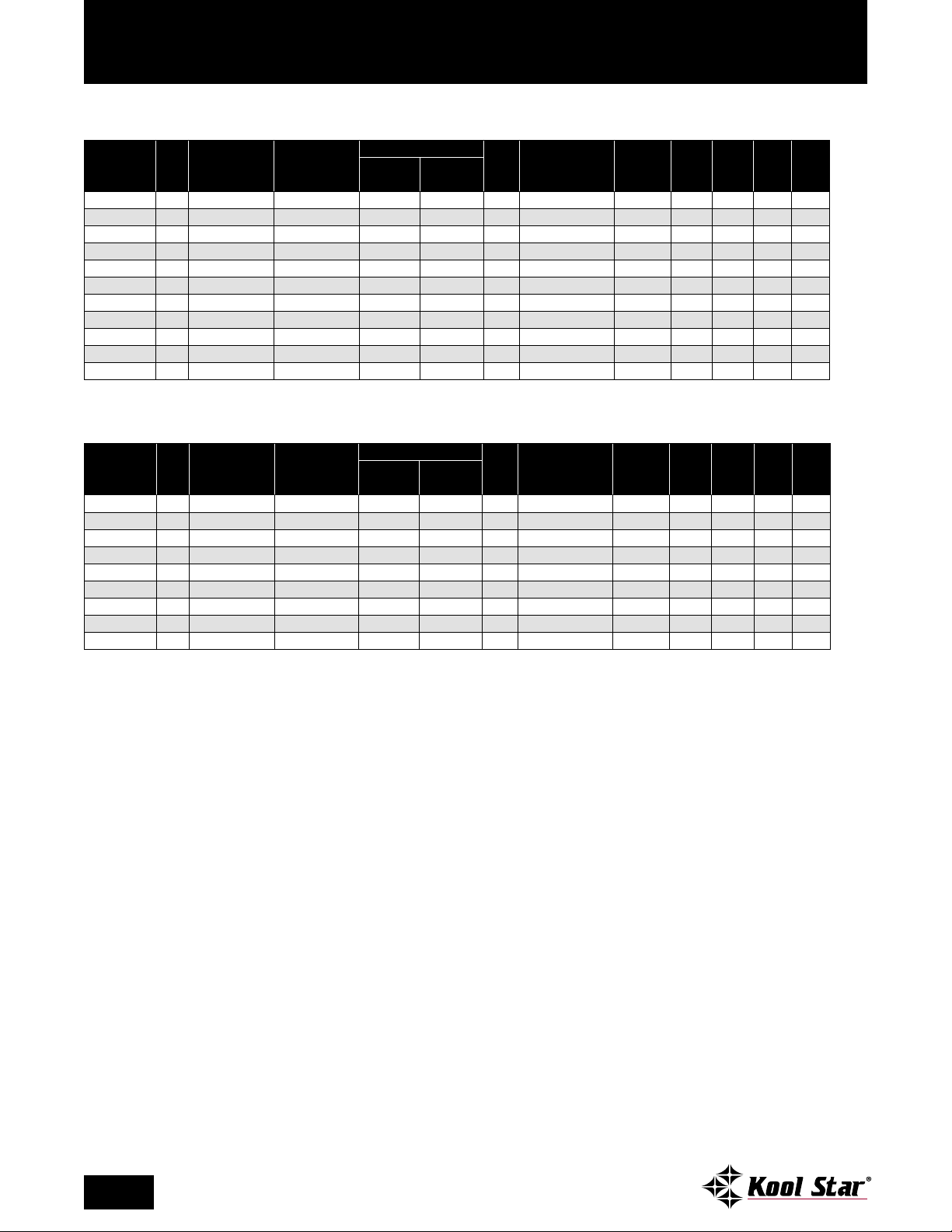
B-Series Low Temperature Specications
R-404A SEMI-HERMETIC CONDENSING UNITS
BTUH @ -20°F
COND. UNIT
MODEL* H.P.
COMPRESSOR
MODEL
SUCTION TEMP.
90°F AMBIENT
BCLZ0280B 3 LALB-032E-CAB 11,560 5/8 1
BCLZ0280C 3 LALA-032E-TAC 11,560 5/8 1
BCLZ0300C 3 2DF3-030E-TFC 14,134 5/8 1
BCLZ0400C 4 2DL3-040E-TFC 16,677 5/8 1
BCLZ0600C 6 2DB3-060E-TFC 20,522 5/8 1
BCLZ0750C 7.5 3DB3-075E-TFC 29,152 7/8 1
BCLZ1000C 10 3DS3-100E-TFC 39,632 7/8 1
BCLZ1500C 15 4DL3-150E-TSK 56,305 7/8 1
BCLZ2200C 22 4DT3-220E-TSK 64,947 7/8 2
BCLZ2700C 27 6DL3-270E-TSK 83,862 1
BCLZ3000C 30 6DT3-300E-TSK 92,877 1
UNIT CONNECTION SIZES
LIQUID SUCTION
1
/
8
1
/
8
3
/
8
3
/
8
3
/
8
3
/
8
3
/
8
5
/
8
1
/
3
/
8
3
/
8
21/
21/
8
8
8
BASE
RECEIVER PUMP
†
SIZE
DOWN CAP. @ 90%
SHIP WT.
(LB/KG) MCA
††
MOP††RLA††LRA
C 41.5 505/230 32 40 15.0 105.0
C 41.5 505/230 32 35 12.6 112.0
C 41.5 505/230 32 45 16.8 102.0
C 41.5 530/241 44 60 26.3 161.0
C 41.5 560/255 46 70 28.2 161.0
D 53.4 730/332 55 80 31.5 161.0
E 80.8 880/400 71 100 42.0 215.0
F 116.1 990/450 90 125 52.6 278.0
F 116.1 1405/639 107 150 66.0 374.0
P 116.1 1730/786 136 200 80.8 450.0
P 116.1 1800/818 154 225 95.6 470.0
††
R-404A SCROLL CONDENSING UNITS
BTUH @ -20°F
COND. UNIT
MODEL* H.P.
COMPRESSOR
MODEL
SUCTION TEMP.
90°F AMBIENT
BSLZ0300B 3 ZF09K4E-PFV 8590 1/2 7/8 C 25.6 405/184 29 40 16.4 88.0
BSLZ0300C 3 ZF09K4E-TF5 8590 1/2 7/8 C 25.6 405/184 23 30 11.1 77.0
BSLZ0350B 3.5 ZF11K4E-PFV 10,369 1/2 7/8 C 25.6 450/205 35 50 20.7 109.0
BSLZ0350C 3.5 ZF11K4E-TF5 10,369 1/2 7/8 C 25.6 450/205 26 35 13.6 88.0
BSLZ0400B 4 ZF13K4E-PFV 11,758 1/2 7/8 C 41.5 510/232 42 60 26.8 129.0
BSLZ0400C 4 ZF13K4E-TF5 11,758 1/2 7/8 C 41.5 510/232 32 40 15.0 99.0
BSLZ0500B 5 ZF15K4E-PFV 14,572 1/2 7/8 C 41.5 520/236 54 80 31.8 169.0
BSLZ0500C 5 ZF15K4E-TF5 14,572 1/2 7/8 C 41.5 520/236 39 50 21.4 123.0
BSLZ0600C 6 ZF18K4E-TF5 17,375 1/2 7/8 C 41.5 550/250 41 60 23.9 156.0
NOTES:
• Semi-hermetic medium temp units are shipped with P.O.E. oil, which is compatible with opitional refrigerants (contact factory for details).
• Hermetic low temp units are shipped with P.O.E. oil, which is compatible with optional refrigerants (contact factory for details).
*VOLTAGE KEY:
“B” sufx = 208-230 or 230 volt, 60 cycle, one phase
“C” sufx = 200-230 or 208-230 volt, 60 cycle, three phase
†
See pp. 20-22 for unit base drawings.
††
Electrical ratings for condensing unit only. See National Electrical Code if units are combined on a single circuit.
UNIT CONNECTION SIZES
LIQUID SUCTION
BASE
RECEIVER PUMP
†
SIZE
DOWN CAP. @ 90%
SHIP WT.
(LB/KG) MCA
††
MOP††RLA††LRA
††
6
888-478-8600 • FAX: 310-513-8156
Specications subject to change without notice.
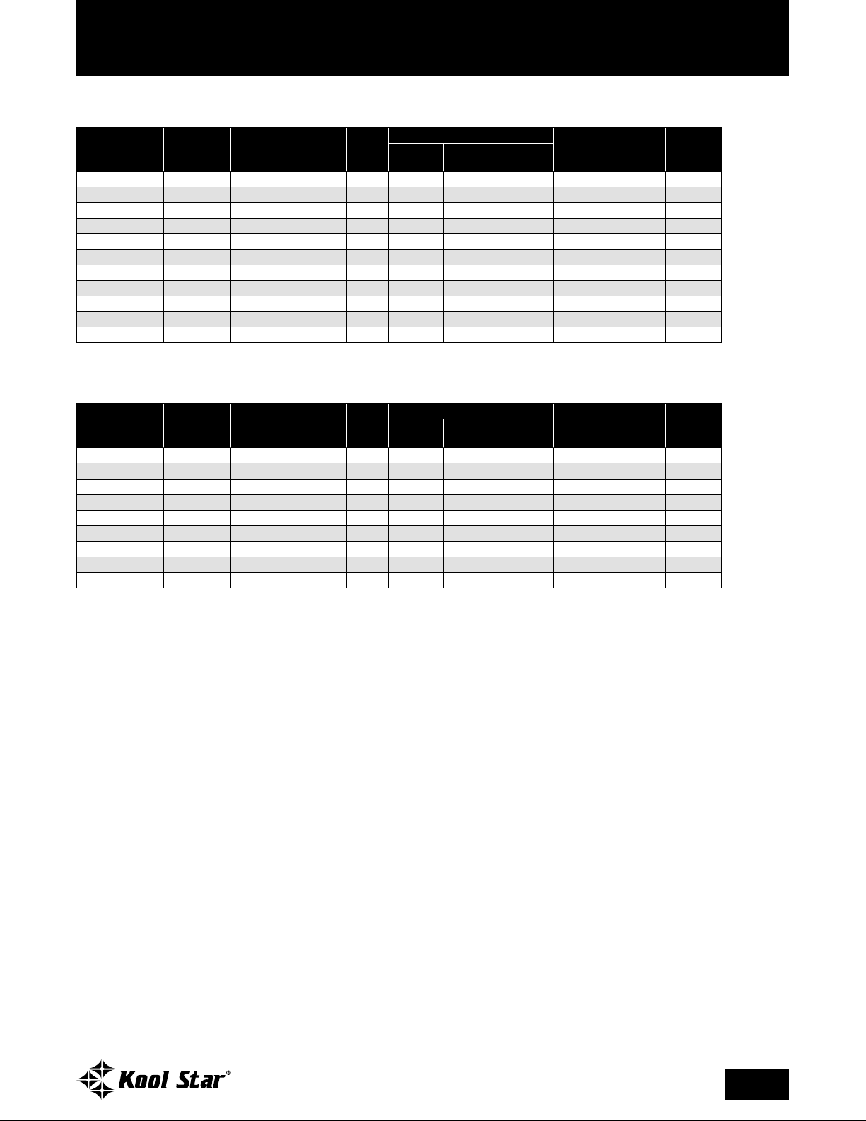
B-Series Low Temperature Specications
MATCHING EVAPORATOR COILS FOR R-404A SEMI-HERMETIC CONDENSING UNITS
BTUH @
EVAPORATOR
MODEL*
E1LZ0160B SE46-164BD 16,000 4 82 15 16 140/64 1.80 17.4
E1LZ0160B SE46-164BD 16,000 4 82 15 16 140/64 1.80 17.4
E1LZ0160B SE46-164BD 16,000 4 82 15 16 140/64 1.80 17.4
E1LZ0240C SE66-245BE 24,500 6 118 15 16 250/114 2.70 22.6
E1LZ0260C IFE26-270E 27,000 2 76 20 25 320/145 4.20 17.0
E1LZ0390C IFE36-385E 38,500 3 106 20 25 450/205 6.30 24.5
E1LZ0520C IFE36-520E 52,000 3 106 20 25 535/243 6.30 24.5
E1LZ0722C PEL4-722E 67,500 4 137 30 33 675/307 20.80 47.8
E1LZ0810C PEL4-817E 76,400 4 137 30 33 726/330 20.80 47.8
E1LZ1020C PEL4-1100E 102,900 4 137 30 51 885/401 20.80 71.3
E1LZ1200C PEL4-1260E 117,800 4 137 30 51 895/407 20.80 71.3
UNIT
PART NO.
SUCTION TEMP.
-20°F**
NO.
FANS
DIMENSIONS (INCHES)
SHIP WT.
(LB/KG)
FAN
AMPS
DEFROST
AMPSL W H
MATCHING EVAPORATOR COILS FOR R-404A SCROLL CONDENSING UNITS
BTUH @
EVAPORATOR
MODEL*
E1LZ0090B SE26-92BD 9200 2 46 15 16 74/34 0.90 8.7
E1LZ0090B SE26-92BD 9200 2 46 15 16 74/34 0.90 8.7
E1LZ0120B SE36-120BD 12,000 3 64 15 16 105/48 1.35 13.0
E1LZ0120B SE36-120BD 12,000 3 64 15 16 105/48 1.35 13.0
E1LZ0160B SE46-164BD 16,000 4 82 15 16 140/64 1.80 17.4
E1LZ0160B SE46-164BD 16,000 4 82 15 16 140/64 1.80 17.4
E1LZ0160B SE46-164BD 16,000 4 82 15 16 140/64 1.80 17.4
E1LZ0160B SE46-164BD 16,000 4 82 15 16 140/64 1.80 17.4
E1LZ0240C SE66-245BE 24,500 6 118 15 16 250/114 2.70 22.6
*VOLTAGE KEY:
“A” sufx = 115 volt, 60 cycle, one phase
“B” sufx = 208-230 volt, 60 cycle, one phase
**Based on 10° T.D.
UNIT
PART NO.
SUCTION TEMP.
-20°F**
NO.
FANS
DIMENSIONS (INCHES)
SHIP WT.
(LB/KG)
FAN
AMPS
DEFROST
AMPSL W H
888-478-8600 • FAX: 310-513-8156
Specications subject to change without notice.
7

B-Series Components
STANDARD COMPONENTS
The B-Series units offer the most complete set of standard features (pre-wired and mounted except
as noted)* These include:
• Liquid line and suction line vibration absorbers (eliminators) for semi-hermetic units only
• Adjustable dual pressure control
• Head pressure control (ooding valve)
• Corrosion-resistant hinged weather hood with lockable snap-down hood latch for easy installation and
service access
• Suction line lter
• Heavy-duty 12 gauge galvanized steel legs
• Pre-wired electrical control panel with timer and circuit breaker or fuse block
• Crankcase heater
• Liquid line lter/drier
• Sight glass
• Liquid and suction line kit with service valve
• Liquid line solenoid valve (shipped loose)
• Timer
• Generously-sized condenser (for 105°F to 110°F ambient)
• Large liquid receiver (good for maximum 250 ft. line run)
• Defrost heater contactor (when required)
• Compressor contactor
• PSC fan motors
• One year limited compressor warranty
*Components may vary depending on horsepower and application. Consult our factory for verication of
standard and optional components.
OPTIONALLY AVAILABLE (CONSULT FACTORY FOR PRICING)
• Water-cooled units
• Special voltages
• Condensing units above 40 H.P.
• Insulated and heated receiver (thermostatically controlled)
• Suction accumulator (shipped loose)
• Coated condenser coils
• Oil separator
• Phase loss/low voltage monitor
• Factory pre-assembled evaporator coil (includes factory pre-mounting of thermostatic air control and
expansion valve)
• Pre-mounted solenoid at evaporator
• Extended four year limited compressor warranty
8
888-478-8600 • FAX: 310-513-8156
Specications subject to change without notice.

M-Series High Ambient Remote Condensing Units
-Series units are similar to the B-Series in
M
components and options. However, M-Series
models are specially designed to function in high
temperature environments.
As with the B-Series, components are pre-wired
and factory mounted. Package options on the basic
standard remote unit include a factory pre-charged
GENEROUSLY-SIZED
CONDENSER
system with quick-connect liquid and suction line
sets up to 40 ft.
M-Series units are available in hermetic, compliant scroll and semi-hermetic compressor models,
with or without matching evaporator coils. They
are factory assembled on a galvanized steel angle
leg base and range from 1/
to 6 H.P.
2
STANDARD PRE-WIRING
STANDARD PRE-PIPING
Components may vary depending on horsepower and application. Consult factory for verication of standard and optional
supplied components.
888-478-8600 • FAX: 310-513-8156
Specications subject to change without notice.
9

M-Series Medium Temperature Specications
R-404A SEMI-HERMETIC CONDENSING UNITS
COND. UNIT
MODEL* H.P.
COMPRESSOR
MODEL
BTUH @ 25°F
SUCTION TEMP.
90°F AMBIENT
UNIT CONNECTION SIZES
LIQUID SUCTION
BASE
RECEIVER PUMP
†
SIZE
DOWN CAP. @ 90%
SHIP WT.
(LB/KG) MCA
††
MOP††RLA††LRA
MCHZ0071C .75 KANA-007E-TAC 6894 3/8 5/8 M1 7.7 270/123 13.0 15 3.0 19.9
MCHZ0081B .75 KANB-007E-CAV 6894 3/8 7/8 M1 7.7 270/123 13.0 15 5.4 36.0
MCHZ0111B 1 KARB-010E-CAV 9214 3/8 7/8 M1 7.7 280/128 19.3 20 7.1 40.0
MCHZ0111C 1 KARA-010E-TAC 9211 3/8 7/8 M1 7.7 280/128 19.3 20 4.3 27.0
MCHZ0181B 2 KAKB-021E-CAV 16,578 1/2 1
MCHZ0211C 2 KAKA-020E-TAC 15,865 1/2 7/8 M2 11.4 450/205 23.0 25 6.5 50.0
MCHZ0221C 2 ERCA-021E-TAC 20,165 1/2 1
MCHZ0311C 3 ERFA-031E-TAC 29,326 1/2 7/8 M3 15.2 500/227 17.6 30 12.4 82.0
MCHZ0321B 3 ERFB-031E-CAB 28,803 5/8 1
MCHZ0321C 3 ERFA-031E-TAC 29,326 5/8 1
MDHZ0511C 5 2DC3R53KE-TFC 45,362 5/8 1
1
/
M2 11.4 450/205 23.0 25 10.1 55.0
8
1
/
M2 11.4 450/205 23.0 25 8.8 46.0
8
1
/
M3 15.2 500/227 38.0 40 17.0 86.0
8
1
/
M3 15.2 500/227 31.8 35 12.4 82.0
8
3
/
M5 22.1 530/241 44.3 50 22.3 120.0
8
R-404A HERMETIC CONDENSING UNITS
BTUH @ 25°F
COND. UNIT
MODEL* H.P.
COMPRESSOR
MODEL
SUCTION TEMP.
90°F AMBIENT
MHHZ0071B .5 RST45C2E-CAV 5979 3/8 5/8 M1 7.7 230/105 13.0 15 5.1 26.5
MHHZ0081B .75 RST55C2E-CAV 7147 3/8 7/8 M1 7.7 240/109 13.0 15 6.8 33.7
MHHZ0111B 1 RS70C1E-PFV 9122 3/8 7/8 M1 7.7 250/114 19.3 20 7.0 34.2
MHHZ0111C 1 RS70C1E-TFC 8955 3/8 7/8 M1 7.7 250/114 19.3 20 4.7 31.0
MHHZ0171B 1.5 CS10K6E-PFV 14,485 1/2 7/8 M2 11.4 360/164 19.6 30 10.9 56.0
MHHZ0171C 1.5 CS10K6E-TF5 14,326 1/2 7/8 M2 11.4 360/164 19.3 20 7.5 51.0
MHHZ0191B 2 CS12K6E-PFV 16,403 1/2 1
MHHZ0191C 2 CS12K6E-TF5 16,248 1/2 1
MHHZ0221B 2.5 CS14K6E-PFV 18,310 1/2 1
MHHZ0221C 2.5 CS14K6E-TF5 18,085 1/2 1
MHHZ0251B 2.75 CS16K6E-PFV 20,188 1/2 1
MHHZ0251C 2.75 CS16K6E-TF5 20,009 1/2 1
MHHZ0301B 3.0 CS18K6E-PFV 25,986 5/8 1
MHHZ0301C 3.0 CS18K6E-TF5 25,618 5/8 1
MHHZ0331B 3.5 CS20K6E-PFV 29,007 5/8 1
MHHZ0331C 3.5 CS20K6E-TF5 28,667 5/8 1
MHHZ0431B 4 CS27K6E-PFV 38,042 5/8 1
MHHZ0431C 4 CS27K6E-TF5 37,491 5/8 1
MHHZ0501B 5 CS33K6E-PFV 44,031 5/8 1
MHHZ0501C 5 CS33K6E-TF5 43,433 5/8 1
UNIT CONNECTION SIZES
LIQUID SUCTION
1
/
8
1
/
8
1
/
8
1
/
8
1
/
8
1
/
8
1
/
8
1
/
8
1
/
8
1
/
8
3
/
8
3
/
8
3
/
8
3
/
8
BASE
RECEIVER PUMP
†
SIZE
DOWN CAP. @ 90%
SHIP WT.
(LB/KG) MCA
††
MOP††RLA††LRA
M2 11.4 360/164 19.6 30 10.9 56.0
M2 11.4 360/164 19.3 20 7.5 51.0
M2 11.4 360/164 23.0 30 12.4 61.0
M2 11.4 360/164 23.0 25 9.1 55.0
M2 11.4 360/164 25.4 40 15.5 73.0
M2 11.4 360/164 23.0 25 9.5 66.0
M3 15.2 302/137 38.0 40 16.0 82.0
M3 15.2 302/137 38.0 40 8.8 65.5
M3 15.2 302/137 38.0 50 18.6 96.0
M3 15.2 302/137 38.0 40 11.4 75.0
M5 22.1 510/232 44.3 60 23.9 95.4
M5 22.1 510/232 44.3 50 13.4 105.0
M5 22.1 530/241 47.5 70 30.7 125.0
M5 22.1 530/241 44.3 50 18.7 102.0
††
††
R-404A SCROLL CONDENSING UNITS
BTUH @ 25°F
COND. UNIT
MODEL* H.P.
COMPRESSOR
MODEL
SUCTION TEMP.
90°F AMBIENT
MSHZ0201B 2 ZB15KCE-PFV 19,382 1/2 7/8 M2 11.4 405/184 22.9 38.6 15.7 61.0
MSHZ0201C 2 ZB15KCE-TF5 19,347 1/2 7/8 M2 11.4 405/184 14.4 23.3 8.9 55.0
MSHZ0251B 2.5 ZB19KCE-PFV 23,495 1/2 7/8 M2 11.4 405/184 25.7 43.6 17.9 73.0
MSHZ0251C 2.5 ZB19KCE-TF5 23,324 1/2 7/8 M2 11.4 405/184 15.8 25.8 10.0 63.0
MSHZ0301B 3 ZB21KCE-PFV 28,162 5/8 7/8 M3 15.2 405/184 28.0 48.7 20.7 100.0
MSHZ0301C 3 ZB21KCE-TF5 28,076 5/8 7/8 M3 15.2 405/184 17.2 29.3 12.1 77.0
MSHZ0351B 4 ZB26KCE-PFV 32,205 5/8 1
MSHZ0351C 4 ZB26KCE-TF5 32,038 5/8 1
MSHZ0401B 4 ZB30KCE-PFV 38,505 1/2 7/8 M5 17.0 510/232 37.2 64.0 26.8 132.0
MSHZ0401C 4 ZB30KCE-TF5 38,238 1/2 7/8 M5 17.0 510/232 23.3 39.0 15.7 115.0
MSHZ0501B 5 ZB38KCE-PFV 46,519 5/8 1
MSHZ0501C 5 ZB38KCE-TF5 46,293 5/8 1
MSHZ0581C 6 ZB45KCE-TF5 53,473 5/8 1
NOTES:
• 134a and 404A compressors are shipped with P.O.E. oil.
• All “M” units include low ambient kit (crankcase heater, head pressure control
valve) as standard feature.
• Other voltages available, please consult factory.
10
888-478-8600 • FAX: 310-513-8156
Specications subject to change without notice.
UNIT CONNECTION SIZES
LIQUID SUCTION
1
/
8
1
/
8
1
/
8
1
/
8
1
/
8
BASE
RECEIVER PUMP
†
SIZE
DOWN CAP. @ 90%
SHIP WT.
(LB/KG) MCA
††
MOP††RLA††LRA
M3 15.2 510/232 31.6 55.2 23.6 127.0
M3 15.2 510/232 17.2 29.3 12.1 77.0
M5 17.0 510/232 42.6 73.7 31.1 175.0
M5 17.0 510/232 31.3 53.4 22.1 115.0
M5 17.0 530/241 33.6 57.5 23.9 156.0
*VOLTAGE KEY:
“B” sufx = 208-230 or 230 volt, 60 cycle, one phase
“C” sufx = 200-230 or 208-230 volt, 60 cycle, three phase
†
See pp. 18-20 for unit base drawings.
††
Electrical ratings for condensing unit only. See National
Electrical Code if units are combined on a single circuit.
††

M-Series Medium Temperature Specications
MATCHING EVAPORATOR COILS FOR R-404A SEMI-HERMETIC CONDENSING UNITS
EVAPORATOR
MODEL*
E1HZ0065A SA18-66 6600 1 28 15 16 50/23 0.9
E1HZ0065A SA18-66 6600 1 28 15 16 50/23 0.9
E1HZ0090A SA28-97BA 9700 2 42 15 16 69/31 1.8
E1HZ0090A SA28-97BA 9700 2 42 15 16 69/31 1.8
E1HZ0156A SA38-160 16,000 3 64 15 16 110/50 2.7
E1HZ0156A SA38-160 16,000 3 64 15 16 110/50 1.8
E1HZ0208A SA48-212BA 21,200 4 82 15 16 145/66 3.6
E1HZ0300A IFA36-305A 30,500 3 76 19 19 320/145 1.8
E1HZ0300A IFA36-305A 30,500 3 76 19 19 320/145 1.8
E1HZ0300A IFA36-305A 30,500 3 76 19 19 320/145 1.8
E1HZ0450A IFA36-460 46,000 3 106 20 25 415/189 2.7
UNIT
PART NO.
BTUH @
SUCTION TEMP.
25°F**
NO.
FANS
DIMENSIONS (INCHES)
MATCHING EVAPORATOR COILS FOR R-404A HERMETIC CONDENSING UNITS
EVAPORATOR
MODEL*
E1HZ0065A SA18-66 6600 1 28 15 16 50/23 0.9
E1HZ0065A SA18-66 6600 1 28 15 16 50/23 0.9
E1HZ0090A SA28-97BA 9700 2 42 15 16 69/31 1.8
E1HZ0090A SA28-97BA 9700 2 42 15 16 69/31 1.8
E1HZ0130A SA28-134 13,400 2 46 15 16 77/35 1.8
E1HZ0130A SA28-134 13,400 2 46 15 16 77/35 1.8
E1HZ0156A SA38-160 16,000 3 64 15 16 110/50 2.7
E1HZ0156A SA38-160 16,000 3 64 15 16 110/50 2.7
E1HZ0156A SA38-160 16,000 3 64 15 16 110/50 2.7
E1HZ0156A SA38-160 16,000 3 64 15 16 110/50 2.7
E1HZ0208A SA48-212 21,200 4 82 15 16 145/66 3.6
E1HZ0208A SA48-212 21,200 4 82 15 16 145/66 3.6
E1HZ0120A (2)
E1HZ0120A (2)
E1HZ0130A (2)
E1HZ0130A (2)
E1HZ0156A (2)
E1HZ0156A (2)
E1HZ0208A (2)
E1HZ0208A (2)
UNIT
PART NO.
††
SA28-122BA (2) 24,400 4 (total) 42 15 16 74/34 3.6 (total)
††
SA28-122BA (2) 24,400 4 (total) 42 15 16 74/34 3.6 (total)
††
SA28-134BA (2) 26800 4 (total) 46 15 16 77/35 3.6 (total)
††
SA28-134BA (2) 26800 4 (total) 46 15 16 77/35 3.6 (total)
††
SA38-160 (2) 32000 6 (total) 64 15 16 110/50 5.4 (total)
††
SA38-160 (2) 32000 6 (total) 64 15 16 110/50 5.4 (total)
††
SA48-212BA (2) 42400 8 (total) 118 15 16 145/66 7.2 (total)
††
SA48-212BA (2) 42400 8 (total) 118 15 16 145/66 7.2 (total)
BTUH @
SUCTION TEMP.
25°F**
NO.
FANS
DIMENSIONS (INCHES)
L W H
†
SHIP WT.
(LB/KG)
FAN
AMPS
DEFROST
AMPSL W H
NOT APPLICABLE
†
SHIP WT.
(LB/KG)
FAN
†
AMPS
†
DEFROST
AMPS
†
NOT APPLICABLE
MATCHING EVAPORATOR COILS FOR R-404A SCROLL CONDENSING UNITS
EVAPORATOR
MODEL*
E1HZ0208A SA48-212BA 21,200 4 82 15 16 145/66 3.6
E1HZ0208A SA48-212BA 21,200 4 82 15 16 145/66 3.6
E1HZ0208A
E1HZ0208A
E1HZ0300A IFA36-305A 30,500 3 76 19 19 320/145 1.8
E1HZ0300A IFA36-305A 30,500 3 76 19 19 320/145 1.8
E1HZ0300A IFA36-305A 30,500 3 76 19 19 320/145 1.8
E1HZ0300A IFA36-305A 30,500 3 76 19 19 320/145 1.8
E1HZ0365A IFA26-370A 37,000 2 76 20 25 360/118 6.0
E1HZ0365A IFA26-370A 37,000 2 76 20 25 360/118 6.0
E1HZ0450A IFA36-490A 49,000 3 106 20 25 415/188 2.7
E1HZ0450A IFA36-490A 49,000 3 106 20 25 415/188 2.7
E1HZ0600B IFA36-620D 62,000 3 106 20 25 520/236 6.3
*VOLTAGE KEY:
“A” sufx = 115 volt, 60 cycle, one phase
**Based on 10° T.D.
†
Dimensions, weights and amps are per evaporator.
††
Evaporator models followed by a number in parentheses indicates that multiple coils are necessary.
UNIT
PART NO.
SA48-212BA
SA48-212BA
BTUH @
SUCTION TEMP.
25°F**
21,200 4 82 15 16 145/66 3.6
21,200 4 82 15 16 145/66 3.6
NO.
FANS
DIMENSIONS (INCHES)
888-478-8600 • FAX: 310-513-8156
Specications subject to change without notice.
†
SHIP WT.
(LB/KG)
FAN
†
AMPS
†
DEFROST
AMPSL W H
NOT APPLICABLE
11

M-Series Low Temperature Specications
R-404A SEMI-HERMETIC CONDENSING UNITS
COND. UNIT
MODEL* H.P.
MCLZ0021B .5
MCLZ0031B .75
MCLZ0031C .75
COMPRESSOR
MODEL
KANB-005E-CAV
KAMB-007E-CAV
KAMA-007E-TAC
BTUH @ -20°F
SUCTION TEMP.
90°F AMBIENT
2170 3/8 5/8 M1 7.7 250/114 6.4 10.0 3.6 24.0
3640 3/8 7/8 M1 7.7 270/123 8.9 14.5 5.6 36.0
3463 3/8 7/8 M1 7.7 270/123 5.9 9.1 3.2 19.9
UNIT CONNECTION SIZES
LIQUID SUCTION
BASE
RECEIVER PUMP
†
SIZE
DOWN CAP. @ 90%
SHIP WT.
(LB/KG) MCA
††
MOP††RLA††LRA
MCLZ0051B 1 KAJB-010E-CAV 4752 3/8 7/8 M1 7.7 280/127 10.5 17.4 6.9 40.0
MCLZ0051C 1 KAJA-011E-TAC 4512 3/8 7/8 M1 7.7 280/127 7.7 12.3 4.6 27.0
MCLZ0071B 1.5 KALB-015E-CAV 6462 3/8 7/8 M1 7.7 310/141 14.3 24.2 9.9 55.0
MCLZ0071C 1.5 KALA-016E-TAC 6408 3/8 7/8 M1 7.7 310/141 10.2 16.8 6.6 50.0
MCLZ0081B 1.5 KATB-015E-CAV 7528 3/8 7/8 M1 7.7 310/141 13.9 23.5 9.6 55.0
MCLZ0081C 1.5 KATA-015E-TAC 7438 3/8 7/8 M1 7.7 310/141 8.2 13.2 5.0 35.5
MCLZ0101B 2 EAVB-021E-CAV 9104 1/2 7/8 M2 11.4 330/150 21.7 36.4 14.7 102.0
MCLZ0101C 2 EAVA-021E-TAC 8755 1/2 7/8 M2 11.4 330/150 12.6 20.0 7.4 50.0
MCLZ0111B 3 3ABB-032E-CAB 10,372 1/2 7/8 M2 11.4 330/150 21.7 36.4 14.7 86.0
MCLZ0111C 3 3ABA-031E-TAC 10,343 1/2 7/8 M2 11.4 330/150 15.8 25.8 10.0 82.0
MCLZ0141B 3 LAHB-032E-CAB 13,799 1/2 1
MCLZ0141C 3 LAHA-032E-TAC 13,903 1/2 1
MCLZ0171B 4
MCLZ0171C 4
NRD1-040E-CFB
NRD1-032E-TFC
16,915 1/2 11/
17,291 1/2 11/
3
/
M2 11.4 500/227 24.2 40.9 16.7 105.0
8
1
/
M2 11.4 500/227 19.3 32.1 12.8 112.0
8
M3 15.2 510/232 36.7 64.4 27.7 115.0
8
M3 15.2 510/232 22.5 38.8 16.3 82.0
8
R-404A HERMETIC CONDENSING UNITS
BTUH @ -20°F
COND. UNIT
MODEL* H.P.
COMPRESSOR
MODEL
SUCTION TEMP.
90°F AMBIENT
MHLZ0021B .5 AFT22C1E-CFV 2210 3/8 5/8 M1 7.7 230/105 6.3 9.8 3.5 34.0
MHLZ0031B .75 AFT29C1E-CFV 2956 3/8 5/8 M1 7.7 240/109 7.4 11.8 4.4 38.7
MHLZ0051B 1 CF04K6E–PFV 3945 3/8 7/8 M1 7.7 240/109 13.9 23.5 9.6 59.0
MHLZ0051C 1 CF04K6E–TF5 3769 3/8 7/8 M1 7.7 240/109 9.9 16.3 6.4 52.0
MHLZ0071B 1.5 CF06K6E–PFV 5938 3/8 1
MHLZ0071C 1.5 CF06K6E–TF5 5722 3/8 1
MHLZ0091B 2 CF09K6E–PFV 9133 1/2 11/
MHLZ0091C 2 CF09K6E–TF5 9230 1/2 1
MHLZ0121B 3 CF12K6E–PFV 11,559 1/2 1
MHLZ0121C 3 CF12K6E–TF5 11,596 1/2 1
UNIT CONNECTION SIZES
LIQUID SUCTION
1
/
8
1
/
8
8
1
/
8
1
/
8
1
/
8
BASE
RECEIVER PUMP
†
SIZE
DOWN CAP. @ 90%
SHIP WT.
(LB/KG) MCA
††
MOP††RLA††LRA
M1 7.7 250/114 16.2 27.6 11.4 59.2
M1 7.7 250/114 10.7 17.7 7.0 52.0
M2 11.4 260/118 23.7 40.0 16.3 87.0
M2 11.4 245/111 15.7 25.6 9.9 65.1
M2 11.4 260/118 27.1 46.1 19.0 105.0
M2 11.4 260/118 18.2 30.1 11.9 85.0
††
††
R-404A SCROLL CONDENSING UNITS
BTUH @ -20°F
COND. UNIT
MODEL* H.P.
COMPRESSOR
MODEL
SUCTION TEMP.
90°F AMBIENT
MSLZ0071B 2 ZF06K4E-PFV 7165 3/8 7/8 M1 7.7 190/86 18.9 32.5 13.6 61.0
MSLZ0071C 2 ZF06K4E-TF5 7165 3/8 7/8 M1 7.7 190/86 13.5 22.8 9.3 55.0
MSLZ0101B 3 ZF09K4E-PFV 10,653 3/8 7/8 M2 11.4 200/91 23.8 40.2 16.4 88.0
MSLZ0101C 3 ZF09K4E-TF5 10,653 3/8 7/8 M2 11.4 200/91 17.2 28.3 11.1 77.0
MSLZ0151B 4 ZF13K4E-PFV 14,994 1/2 7/8 M3 11.4 230/105 36.8 63.6 26.8 129.0
MSLZ0151C 4 ZF13K4E-TF5 14,994 1/2 7/8 M3 11.4 230/105 22.1 37.1 15.0 99.0
MSLZ0181B 5 ZF15K4E-PFV 18,970 1/2 1
MSLZ0181C 5 ZF15K4E-TF5 18,945 1/2 1
MSLZ0221C 6 ZF18K4E-TF5 23,018 1/2 1
UNIT CONNECTION SIZES
LIQUID SUCTION
1
/
8
1
/
8
1
/
8
BASE
RECEIVER PUMP
†
SIZE
DOWN CAP. @ 90%
SHIP WT.
(LB/KG) MCA
††
MOP††RLA††LRA
M3 15.2 240/109 41.9 73.7 31.8 169.0
M3 15.2 240/109 28.9 50.3 21.4 123.0
M4 17.0 250/114 33.6 57.5 23.9 156.0
R-404A DISCUS CONDENSING UNITS
BTUH @ -20°F
COND. UNIT
MODEL* H.P.
COMPRESSOR
MODEL
SUCTION TEMP.
90°F AMBIENT
MDLZ0201C 3 2DF3-030E-TFC 19,518 1/2 11/
MDLZ0231C 4 2DL3-040E-TFC 22,958 1/2 1
MDLZ0291C 6
MDLZ0331C 6
2DB3F25KE-TFC
3DA3A060E-TFC
29,187 5/8 13/
32,417 5/8 13/
NOTES:
• 134a and 404A compressors are shipped with P.O.E. oil.
• All “M” units include low ambient kit (crankcase heater, head pressure control
valve) as standard feature.
• Other voltages available, please consult factory.
12
888-478-8600 • FAX: 310-513-8156
Specications subject to change without notice.
UNIT CONNECTION SIZES
LIQUID SUCTION
8
1
/
8
8
8
BASE
RECEIVER PUMP
†
SIZE
DOWN CAP. @ 90%
SHIP WT.
(LB/KG) MCA
††
MOP††RLA††LRA
M3 15.2 530/241 23.1 39.9 16.8 102.0
M3 15.2 530/241 35.0 61.3 26.3 161.0
M4 17.0 560/255 39.0 67.2 28.2 161.0
M4 17.0 560/255 41.6 71.9 30.3 150.0
*VOLTAGE KEY:
“B” sufx = 208-230 or 230 volt, 60 cycle, one phase
“C” sufx = 200-230 or 208-230 volt, 60 cycle, three phase
†
See pp. 18-20 for unit base drawings.
††
Electrical ratings for condensing unit only. See National
Electrical Code if units are combined on a single circuit.
††
††

M-Series Low Temperature Specications
MATCHING EVAPORATOR COILS FOR R-404A SEMI-HERMETIC CONDENSING UNITS
BTUH @
EVAPORATOR
MODEL*
E1LZ0035B SE16-36 3600 1 28 15 16 41/19 1.0 4.4
E1LZ0035B SE16-36 3600 1 28 15 16 41/19 1.0 4.4
E1LZ0035B SE16-36 3600 1 28 15 16 41/19 1.0 4.4
E1LZ0047B SE16-46 4600 1 28 15 16 47/21 1.0 4.4
E1LZ0047B SE16-46 4600 1 28 15 16 47/21 1.0 4.4
E1LZ0065B SE26-60 6000 2 42 15 16 61/28 2.0 7.0
E1LZ0065B SE26-60 6000 2 42 15 16 61/28 2.0 7.0
E1LZ0075B SE26-75 7500 2 42 15 16 67/30 2.0 7.0
E1LZ0075B SE26-75 7500 2 42 15 16 67/30 2.0 7.0
E1LZ0090B SE26-92 9200 2 46 15 16 74/34 2.0 8.7
E1LZ0090B SE26-92 9200 2 46 15 16 74/34 2.0 8.7
E1LZ0090B SE26-92 9200 2 46 15 16 74/34 2.0 8.7
E1LZ0090B SE26-92 9200 2 46 15 16 74/34 2.0 8.7
E1LZ0141B SE36-140 14,000 3 64 15 16 115/52 3.0 13
E1LZ0141B SE36-140 14,000 3 64 15 16 115/52 3.0 13
E1LZ0160B SE46-164 16,400 4 82 15 16 140/64 4.0 17.4
E1LZ0160B SE46-164 16,400 4 82 15 16 140/64 4.0 17.4
UNIT
PART NO.
SUCTION TEMP.
-20°F**
NO.
FANS
DIMENSIONS (INCHES)
†
MATCHING EVAPORATOR COILS FOR R-404A HERMETIC CONDENSING UNITS
BTUH @
EVAPORATOR
MODEL*
E1LZ0035B SE16-36 3600 1 28 15 16 41/19 1.0 4.4
E1LZ0035B SE16-36 3600 1 28 15 16 41/19 1.0 4.4
E1LZ0047B SE16-46 4600 1 28 15 16 47/21 1.0 4.4
E1LZ0035B SE16-36 3600 1 28 15 16 41/19 1.0 4.4
E1LZ0065B SE26-60 6000 2 42 15 16 61/28 2.0 7.0
E1LZ0065B SE26-60 6000 2 42 15 16 61/28 2.0 7.0
E1LZ0090B SE26-92 9200 2 46 15 16 74/34 2.0 8.7
E1LZ0090B SE26-92 9200 2 46 15 16 74/34 2.0 8.7
E1LZ0120B SE36-120 12,000 3 64 15 16 105/48 3.0 13
E1LZ0120B SE36-120 12,000 3 64 15 16 105/48 3.0 13
UNIT
PART NO.
SUCTION TEMP.
-20°F**
NO.
FANS
DIMENSIONS (INCHES)
†
†
SHIP WT.
(LB/KG)
†
SHIP WT.
(LB/KG)
FAN
AMPS
FAN
AMPS
DEFROST
AMPSL W H
DEFROST
AMPSL W H
MATCHING EVAPORATOR COILS FOR R-404A SCROLL CONDENSING UNITS
BTUH @
EVAPORATOR
MODEL*
E1LZ0075B SE26-75 7500 2 42 15 16 67/30 2.0 7
E1LZ0075B SE26-75 7500 2 42 15 16 67/30 2.0 7
E1LZ0090B SE26-92 9200 2 46 15 16 74/34 2.0 8.7
E1LZ0090B SE26-92 9200 2 46 15 16 74/34 2.0 8.7
E1LZ0141B SE36-140 14,000 3 64 15 16 115/52 3.0 13
E1LZ0141B SE36-140 14,000 3 64 15 16 115/52 3.0 13
E1LZ0180B SE46-185 18,500 4 82 15 16 155/70 4.0 17.4
E1LZ0180B SE46-185 18,500 4 82 15 16 155/70 4.0 17.4
E1LZ0200B SE56-210 21,000 5 100 15 16 225/102 5.0 21.8
UNIT
PART NO.
SUCTION TEMP.
-20°F**
NO.
FANS
DIMENSIONS (INCHES)
†
†
SHIP WT.
(LB/KG)
FAN
AMPS
DEFROST
AMPSL W H
MATCHING EVAPORATOR COILS FOR R-404A DISCUS CONDENSING UNITS
BTUH @
EVAPORATOR
MODEL*
E1LZ0180B SE46-185 18,500 4 82 15 16 155/70 4.0 17.4
E1LZ0200B SE56-210 21,000 5 100 15 16 225/102 5.0 21.8
E1LZ0280B SE66-280 28,000 6 118 15 16 270/123 6.0 26.1
E1LZ0160B (2)
*VOLTAGE KEY:
“B” sufx = 208-230 volt, 60 cycle, one phase
**Based on 10° T.D.
†
Dimensions, weights and amps are per evaporator.
††
Evaporator models followed by a number in parentheses indicates that multiple coils are necessary.
UNIT
PART NO.
††
SE46-164 (2) 32,800 (total) 8 (total) 82 15 16 140/64 4.0 34.8
SUCTION TEMP.
-20°F**
NO.
FANS
DIMENSIONS (INCHES)
L W H
†
SHIP WT.
(LB/KG)
FAN
†
AMPS
†
DEFROST
AMPS
†
888-478-8600 • FAX: 310-513-8156
Specications subject to change without notice.
13

M-Series Components
STANDARD COMPONENTS
The M-Series set of standard features (pre-wired and mounted except as noted)* include:
• Liquid line and suction line vibration absorbers (eliminators) for semi-hermetic units only
• Preset non-adjustable high pressure control and preset non-adjustable low pressure control**
• Crankcase heater
• Head pressure control (ooding valve)
• Heavy gauge, galvanized steel mechanically-fastened weather hood
• Suction service valve
• Heavy-duty angle leg base
• Liquid line lter/drier
• Pre-wired electrical control panel
• Sight glass
• Liquid and suction line kit with service valve
• Timer (standard on low temp units only)
• Compressor contactor
• Defrost heater contactor (when required)
• Generously-sized condenser (rated up to 120°F ambient)
• Ried tubes in condenser for greater efciency
• PSC condenser fan motors
• Large liquid receiver (good for maximum 100 ft. line run)
• Liquid line shut-off valve for easy change of lter
• One year limited compressor warranty
*Components may vary depending on horsepower and application. Consult our factory for verication of
standard and optional components.
**Preset high pressure control and preset low pressure control are non-adjustable in medium temp M-Series
units. The low pressure control is adjustable in low temp units.
OPTIONALLY AVAILABLE (CONSULT FACTORY FOR PRICING)
• Special voltages
• Insulated and heated receiver (thermostatically controlled)
• Suction accumulator (shipped loose)
• Coated condenser coils
• Oil separator
• Phase loss/low voltage monitor
• Factory pre-assembled evaporator coil (includes factory pre-mounting of thermostatic air control and
expansion valve)
• Factory pre-charged system with quick connect liquid and suction line sets up to 50 ft. (specify length
when ordering)
• Adjustable low pressure control for medium and high temp units
• Dual pressure control
• Circuit breaker
• Suction lter
• Fan cycling switch
• Pre-mounted solenoid at evaporator
• Liquid line solenoid valve (shipped loose)
• Timer for medium temp units
• Heavy-duty channel leg base
• Extended four year limited compressor warranty
14
888-478-8600 • FAX: 310-513-8156
Specications subject to change without notice.

DRS Series Dual Compressor Systems
hen your requirements call for two-compres-
W
answer. These systems are designed to allow the
remoting of refrigeration units in walk-ins, reachins and other refrigerated equipment to a single
system. Benets include reductions in inside heat,
sor condensing unit, the DRS series is the
air conditioning load and noise levels.
Featuring a common base and frame assembly, DRS
sytems use scroll compressors for freezer applications
up to 5 HP and hermetic compressors for cooler applications up to 3 HP.
Features Benets
Galvanized housing with louvred doors (stainless steel nish
optional)
Modules equipped with head masters and crankcase heaters Provides protection in low ambient temperature situations
System designed for increased air ow across compressors Efcient cooling
Time clocks for both low and medium temp compressors For ease of service and optional defrost scheduling
Pre-wired electrical panel
with one-point connection
and a disconnect switch
included.
Durable, weather-resistant enclosure
Multi-circuited condenser
coil designed for 110°F
ambient.
888-478-8600 • FAX: 310-513-8156
Specications subject to change without notice.
15

DRS Series Dual Compressor Systems
BTUH
CAPACITY
SYSTEMS
COMPRESSOR
UNIT
MODELS
RSPR1102C
RSPR1104C
RSPR1106C
RSPR1108C
RSPR1110C
RSPR1112C
RSPR1114C
RSPR1116C
RSPR1118C
RSPR1120C
RSPR1122C
RSPR1124C
RSPR1126C
RSPR1128C
RSPR1130C
RSPR1132C
TEMP
HP -10°F 35°F RLA LRA
Med. 3/4 RST55C1E-CAV 6790 4.95 6.1 33.7
Low 1
1
Med. 1/2 RST45C1E-CAV 5530 4.95 4.6 26.5
Low 1
1
Med. 1 RS70C1E-TFC 9180 4.95 4.7 31.0
Low 1
Med. 1
Low 1
1
1
1
Med. 3/4 RST55C1E-CAV 6790 4.95 6.1 33.7
Low 2 ZF06K4E-TF5 7090 11.3 9.3 55.0 3/8 7/8 E1LZ0075B
Med. 1/2 RST45C1E-CAV 5530 4.95 4.6 26.5
Low 2 ZF06K4E-TF5 7090 11.3 9.3 55 3/8 7/8 E1LZ0075B
Med. 1 RS70C1E-TFC 9180 4.95 4.7 31.0
Low 2 ZF06K4E-TF5 7090 11.3 9.3 55 3/8 7/8 E1LZ0075B
Med. 1
1
Low 2 ZF06K4E-TF5 7090 11.3 9.3 55 3/8 7/8 E1LZ0075B
Med. 3/4 RST55C1E-CAV 6790 4.95 6.1 33.7
Low 3 ZF09K4E-TF5 10,100 15.1 11.1 77.0 3/8 7/8 E1LZ0090B
Med. 1/2 RST45C1E-CAV 5530 4.95 4.6 26.5
Low 3 ZF09K4E-TF5 10,100 15.1 11.1 77 3/8 7/8 E1LZ0090B
Med. 1 RS70C1E-TFC 9180 4.95 4.7 31.0
Low 3 ZF09K4E-TF5 10,100 15.1 11.1 77 3/8 7/8 E1LZ0090B
Med. 1
1
Low 3 ZF09K4E-TF5 10,100 15.1 11.1 77 3/8 7/8 E1LZ0090B
Med. 3/4 RST55C1E-CAV 6790 4.95 6.1 33.7
Low 4 ZF13K4E-TF5 14,200 15.1 15.0
Med. 1/2 RS43C1E-CAV 5490 4.95 5.4 24.1
Low 4 ZF13K4E-TF5 14,200 15.1 15.0 99 1/2 7/8 E1LZ0140B
Med. 1 RS70C1E-TFC 9180 4.95 4.7 31.0
Low 4 ZF13K4E-TF5 14,200 15.1 15.0 99 1/2 7/8 E1LZ0140B
Med. 1
1
MODELS
/2CF06K6E-TF5 5190 4.95 7.0 52.0 3/8 11/
/2CF06K4E-TF5 5190 4.95 7.0 52 3/8 11/
/2CF06K6E-TF5 5190 4.95 7.0 52 3/8 11/
/2CS10K6E-TF5 13,500 11.3 7.5 51.0
/2CF06K6E-TF5 5190 4.95 7.0 52 3/8 11/
/2CS10K6E-TF5 13,500 11.3 7.5 51.0
/2CS10K6E-TF5 13,500 11.3 7.5 51.0
/2CS10K6E-TF5 13,500 11.3 7.5 51.0
Low 4 ZF13K4E-TF5 14,200 15.1 15.0 99 1/2 7/8 E1LZ0140B
RSPR1134C
RSPR1136C
RSPR1138C
Med. 1 RS70C1E-TFC 9180 4.95 4.7 31.0
Low 5 ZF15K4E-TF5 17,700 16.9 21.4 123 1/2 1
Med. 1
1
/2CS10K6E-TF5 13,500 11.3 7.5 51.0
Low 5 ZF15K4E-TF5 17,700 16.9 21.4 123 1/2 1
Med. 2 CS12K6E-TFC 15,900 11.3 7.5 51.0
Low 5 ZF15K4E-TF5 17,700 16.9 21.4 123 1/2 1
NOTE: ALL SYSTEMS USE R-404A REFRIGERANT AND ARE 208-230V/60/3.
@ ROOM
TEMP.
10°F TD,
90° AMBIENT
RECEIVER
90%/
90°F
COMPRESSOR
99.0 1/2 7/8 E1LZ0140B
SHIP
WT.
CONNECTIONS
LBS
(KG)
LIQUID SUCTION
3/8 7/8
392
(178)
3/8 5/8
384
(175)
3/8 7/8
400
(182)
1/2 7/8
488
(222)
3/8 7/8
344
(156)
3/8 5/8
336
(153)
3/8 7/8
352
(160)
1/2 7/8
440
(200)
3/8 7/8
352
(160)
3/8 5/8
344
(156)
3/8 7/8
360
(164)
1/2 7/8
448
(204)
3/8 7/8
376
(171)
3/8 5/8
368
(167)
3/8 7/8
384
(175)
1/2 7/8
472
(215)
3/8 7/8
392
(178)
1/2 7/8
480
(218)
1/2 1
480
(218)
RLA
22.9 21.25 25
8
21.6 19.75 25
8
20.9 19.85 25
8
23.7 22.78 30
8
25.2 24.13 30
23.9 22.63 30
23.2 22.73 30
26.0 25.53 30
27.0 28.03 35
25.7 26.15 35
25.0 28.28 35
27.8 30.40 40
30.9 36.53 45
29.6 34.65 45
28.9 34.78 45
31.7 38.28 45
35.3 41.85 60
1
/
8
38.1 44.65 60
1
/
8
1
/
8
38.1 44.65 60
1
/
8
MCA MOP
EVAP.
MODEL
E1HZ0065A
E1LZ0047B
E1HZ0052A
E1LZ0047B
E1HZ0090A
E1LZ0047B
E1HZ0120A
E1LZ0047B
E1HZ0065A
E1HZ0052A
E1HZ0090A
E1HZ0120A
E1HZ0065A
E1HZ0052A
E1HZ0090A
E1HZ0120A
E1HZ0065A
E1HZ0052A
E1HZ0090A
E1HZ0120A
E1HZ0090A
E1LZ0160B
E1HZ0120A
E1LZ0160B
E1HZ0156A
E1LZ0160B
16
888-478-8600 • FAX: 310-513-8156
Specications subject to change without notice.

DRS Series Dual Compressor Systems
MATCHING MEDIUM TEMP EVAPORATOR COILS FOR DRS UNITS
EVAPORATOR
MODEL*
E1HZ0052A SA18-53BA 6360 1 28 15 16 46/21 0.90
E1HZ0065A SA18-66BA 7920 1 28 15 16 50/23 0.90
E1HZ0090A SA28-97BA 11,640 2 42 15 16 69/31 1.80
E1HZ0120A SA28-122BA 12,200 2 42 15 16 74/34 1.80
E1HZ0156A SA38-160 16,000 3 64 15 16 110/50 2.7
UNIT
PART NO.
BTUH @
SUCTION TEMP. 25°F**
NO.
FANS
DIMENSIONS (INCHES)
†
L W H
MATCHING LOW TEMP EVAPORATOR COILS FOR DRS UNITS
†
SHIP WT.
(LB/KG)
FAN
AMPS
DEFROST
AMPS
N/A
N/A
N/A
N/A
N/A
EVAPORATOR
MODEL*
E1LZ0047B SE16-46 4600 1 28 15 16 47/21 1.0 4.4
E1LZ0065B SE26-60BD 6000 2 42 15 16 61/28 0.90 7.0
E1LZ0075B SE26-75BD 7500 2 42 15 16 67/30 0.90 7.0
E1LZ0090B SE26-92BD 9200 2 46 15 16 74/34 0.90 8.7
E1LZ0120B SE36-120BD 12,000 3 64 15 16 105/48 1.35 13.0
E1LZ0140B IFE26-150D 13,400 2 55 19 19 140/64 4.20 20.3
E1LZ0160B SE46-164 16,400 4 82 15 16 140/64 4.0 17.4
*VOLTAGE KEY:
“A” sufx = 115 volt, 60 cycle, one phase
“B” sufx = 208-230 volt, 60 cycle, one phase
**Based on 10° T.D.
†
No. of fans and dimensions are per evaporator
UNIT
PART NO.
BTUH @
SUCTION TEMP. -20°F**
NO.
FANS
DIMENSIONS (INCHES)
†
L W H
†
SHIP WT.
(LB/KG)
FAN
AMPS
DEFROST
AMPS
888-478-8600 • FAX: 310-513-8156
Specications subject to change without notice.
17

Condensing Unit Base Specications
BASE “A”
BASE “B”
BASE “C”
BASE “D”
18
888-478-8600 • FAX: 310-513-8156
Specications subject to change without notice.

BASE “E”
191-1/2"
168-1/4"
58-1/4"
42"
Piping Connections
1-1/2" Dia.
Lifting Holes
BASE “F”
Condensing Unit Base Specications
BASE “N”
BASE “P”
888-478-8600 • FAX: 310-513-8156
Specications subject to change without notice.
19

Condensing Unit Base Specications
BASE “R”
BASE “M1”
BASE “M2”
BASE “M3”
BASE “M5”
20
888-478-8600 • FAX: 310-513-8156
Specications subject to change without notice.

PRS-2 Packaged Refrigeration Systems
he combination of a condensing unit and
T
evaporator coil together in one convenient
package saves time and installation costs for walkins located in c-stores, restaurants and many other
Compressor
foodservice applications.
Also designed to maximize storage space, the
evaporator section mounts ush in a standard 4"
walk-in ceiling or wall panel.
Evaporator fans
Evaporator coil
Condenser coil
Electrical box
containing
defrost timer
PRS-2 units are available in both indoor and outdoor models. Outdoor models (middle) are standard with a crankcase
heater, drainline heater, head master and weather hood. Outdoor and indoor wall mount models (right) are also available.
888-478-8600 • FAX: 310-513-8156
Specications subject to change without notice.
21

ROOM TEMP.
MODEL NO.
PRS-2 Packaged Refrigeration System Specications
BTUH
@ 90°F
PRS-2
MODEL*
CEILING MOUNT COOLER SYSTEMS
PHHZ0050A N/A 5630 R-404A NS .5 14 20 10.1 51.0 115/60/1 5-20P 230/105
PHHZ0050AT N/A 5630 R-404A NS .5 14 20 10.1 51.0 115/60/1 N/A 275/125
PHHZ0070B N/A 7740 R-404A NM .75 11 15 7.7 37.0 208-230/60/1 6-20P 320/145
PHHZ0070BT N/A 7740 R-404A NM .75 11 15 7.7 37.0 208-230/60/1 N/A 360/164
PHHZ0100B N/A 11,200 R-404A NL 1 17 20 11.0 51.0 208-230/60/1 N/A 410/186
PHHZ0100BT N/A 11,200 R-404A NL 1 17 20 11.0 51.0 208-230/60/1 N/A 480/218
CEILING MOUNT FREEZER SYSTEMS
PHXZ0070B
PHXZ0070BT
PHXZ0100B
PHXZ0100BT
PHXZ0125B
PHXZ0125BT
PHXZ0150B
PHXZ0150BT
PHXZ0200B
PHXZ0200BT
PHXZ0201B
PHXZ0201BT
*Outdoor models denoted with a “T” sufx. See chart below.
-10°F BOX
TEMP
2700
2700
3680
3680
3980
3980
6060
6060
6510
6510
8000
8000
BTUH @
90°F
35°F BOX
TEMP
N/A R-404A NM .75 11 15 7.7 37.0 208-230/60/1 6-20P 280/127
N/A R-404A NM .75 11 15 7.7 37.0 208-230/60/1 N/A 310/141
N/A R-404A NM 1 13 20 9.6 46.0 208-230/60/1 N/A 370/168
N/A R-404A NM 1 13 20 9.6 46.0 208-230/60/1 N/A 410/186
N/A R-404A NL 1.2 12 15 8.4 46.0 208-230/60/1 N/A 465/211
N/A R-404A NL 1.2 12 15 8.4 46.0 208-230/60/1 N/A 510/232
N/A R-404A NL 1.5 17 25 11.4 59.0 208-230/60/1 6-20P 525/239
N/A R-404A NL 1.5 17 25 11.4 59.0 208-230/60/1 N/A 565/257
N/A R-404A NL 2 17 25 11.4 59.0 208-230/60/1 6-20P 525/239
N/A R-404A NL 2 17 25 11.4 59.0 208-230/60/1 N/A 565/257
N/A R-404A NL 2 18 20 11.2 87.0 208-230/60/1 N/A 611/278
N/A R-404A NL 2 17 20 11.0 87.0 208-230/60/1 N/A 691/314
REFG.
TYPE
DIMENSIONS
SEE FIGURE... HP
ELECTRICAL DATA
NEMA
PLUG
TYPE
SHIP
WT.
LB/KGMCA MOP RLA LRA VOLTAGE
Refrigeration System Nomenclature
Refrigeration System Dimensions
Figure NS Figure NM
22
Figure NL
888-478-8600 • FAX: 310-513-8156
Specications subject to change without notice.
Consult Factory For
Agency Listings

PRS-2 Packaged Refrigeration System Specications
ROOM TEMP.
MODEL NO.
BTUH
@ 90°F
PRS-2
MODEL*
WALL MOUNT COOLER SYSTEMS
WHHZ0030A N/A 3251 R-404A NSW 1/3 14.4 20 9.1 NA 115/60/1 5-20P 294/133
WHHZ0030AT
WHHZ0050B N/A 5709 R-404A NLW 1/2 9.7 15 6.3 NA 208-230/60/1 6-20P 480/217
WHHZ0050BT
WALL MOUNT FREEZER SYSTEMS
WHXZ0030B 2110 N/A R-404A NSW 1/3 8.3 15 4.4 8.3 208-230/60/1 6-20P 321/145
WHXZ0030BT
WHXZ0050B 2845 N/A R-404A NSW 1/2 9.9 15 4.4 9.9 208-230/60/1 6-20P 478/216
WHXZ0050BT
WHXZ0700B 3960 N/A R-404A NLW 3/4 9.7 15 6.3 7.1 208-230/60/1 6-20P 529/239
WHXZ0700BT
WHXZ0100B 5560 N/A R-404A NLW 1 14.2 20 8.5 7.1 208-230/60/1 6-20P 549/248
WHXZ0100BT
WHXZ0101BT
WHEZ0050B 2590 N/A R-404A NSW 1/2 9.3 15 6.3 8.3 208-230/60/1 6-20P 529/239
WHEZ0100B 5708 N/A R-404A NLW 1 14.9 20 8.5 7.1 208-230/60/1 6-20P 639/289
*Outdoor models denoted with a “T” sufx. See chart below.
-10°F BOX
TEMP
N/A 3251 R-404A NSW 1/3 14.7 20 9.1 NA 115/60/1 5-20P 296/134
N/A 5709 R-404A NLW 1/2 10.6 15 6.3 NA 208-230/60/1 6-20P 487/220
2110 N/A R-404A NSW 1/3 9.6 15 4.4 9.6 208-230/60/1 6-20P 323/146
2845 N/A R-404A NSW 1/2 9.9 15 4.4 9.9 208-230/60/1 6-20P 480/217
3960 N/A R-404A NLW 3/4 10.1 15 6.3 7.1 208-230/60/1 6-20P 531/240
5560 N/A R-404A NLW 1 14.6 20 8.5 7.1 208-230/60/1 6-20P 581/263
5560 N/A R-404A NLW 1 14.4 20 8.5 7.1 230/60/1 6-20P 583/264
BTUH @
90°F
35°F BOX
TEMP
REFG.
TYPE
DIMENSIONS
SEE FIGURE... HP
ELECTRICAL DATA
NEMA
PLUG
TYPE
SHIP
WT.
LB/KGMCA MOP RLA LRA VOLTAGE
Refrigeration System Nomenclature
Refrigeration System Dimensions
Figure NLW
888-478-8600 • FAX: 310-513-8156
Specications subject to change without notice.
Figure NSW
Consult Factory For
Agency Listings
23

Notes
24
888-478-8600 • FAX: 310-513-8156
Specications subject to change without notice.

888-478-8600 • FAX: 310-513-8156
Specications subject to change without notice.

21720 South Wilmington Ave.
Bldg. 450, Suite 308
Long Beach, CA 90810
Phone: 888-478-8600
Fax: 310-513-8156
www.koolstar.com
Due to continuous product enhancements, we reserve the
right to change specications without notice.
1349-3/10 ©2010 Kool Star division of Standex International, Inc. All rights reserved.
Printed in USA.
 Loading...