


2 | P a g e
Notes to Users
We appreciate you purchasing a Koolsola solar hybrid air conditioner. You will enjoy the benefits in terms of
power saving and affordable comfort for many years to come. To understand how your Koolsola works and to
ensure the best performance from your solar air conditioner please read the following information before
installing or using the system.
Ⅰ The
Installation Guide
is information specifically for professional installers.
Ⅱ Before using the solar air conditioner, please read the Safety Information to avoid damage to the solar air
conditioner or other issues as a result of incorrect operation.
Ⅲ Please turn off the power to the solar air conditioner when not in use.
Ⅳ The correct installation and use will ensure the best performance from your solar air conditioner. Please
read the
Operating Instructions
before installation, maintenance and use.
Ⅴ The
Specifications
of your solar air conditioner and the
Operating Instructions
are subject to change
without notice.
Ⅵ The product is manufactured to International Standard Q/320581FSC001-2006
The Performance Characteristics of Solar Air Conditioners
The Koolsola product uses solar thermal energy to improve the operation of the condenser thus
reducing the amount of electrical energy required for operation
Once stability is reached, the compressor is only required infrequently. Service life is therefore
extended.
The condenser is 10dBA quieter than conventional. The fan head uses an advanced off-center blade
fan and foam air duct. This results in higher performance and lower noise.
The reverse cycle function enables economical heating on cold days
The design is elegant and graceful while practical.
It uses microprocessor control. The operation is convenient and simple. The solar air conditioner is also
provided with an automatic detection display system. You will feel comfortable and socially responsible with
our solar air conditioner.

3 | P a g e
CONTENTS
Ⅰ. The Performance Characteristics of your Koolsola Solar Air Conditioner……………………….. 2
Ⅱ. Operating Instructions………………………………………………………………………………… 4
III. System Specifications……………………………………………………………………………….…… 6
Ⅲ. IV. Safety Notice………………………..……………………………………………….……………….. 16
V. Solar Air Conditioner Application……………………….……….………….…………………………… 18
VI. Solar Air Conditioner Component description………………………….…………………………..….. 20
Ⅵ. Remote Control Function……………………….…………..…………………….……………………. 21
Ⅶ. Repair and Maintenance……………………………………….……………………………………….. 25
1.Common Faults and Solutions……………………………………………………..……………….. 27
2.Common Faults Diagnosis and Elimination……………………………………………………….. 29
Ⅷ. Solar Air-conditioner Installation……………………………………………………………………….. 30
1.Installation Guide……………………….…………………………………………………………….. 30
2.Indoor Unit Installation……………………….…………………..………………………………….. 31
3.Solar Collector Installation……………………………………….………………………………….. 35
4. CondensateTube ……………………………………………..…………………………………….. 37
5.Empty the air…………………………………………………………………..…………………….. 38
6. Extra pipe and refrigerant…………………………………………….…………………………….. 40
Ⅸ.The Circuit Diagram…………………………………………….……………………………………….. 42
Ⅹ.The Packing List……………………………………………………….………………………………… 45
4 | P a g e
Operating Instructions
1.Part Names and
Functions
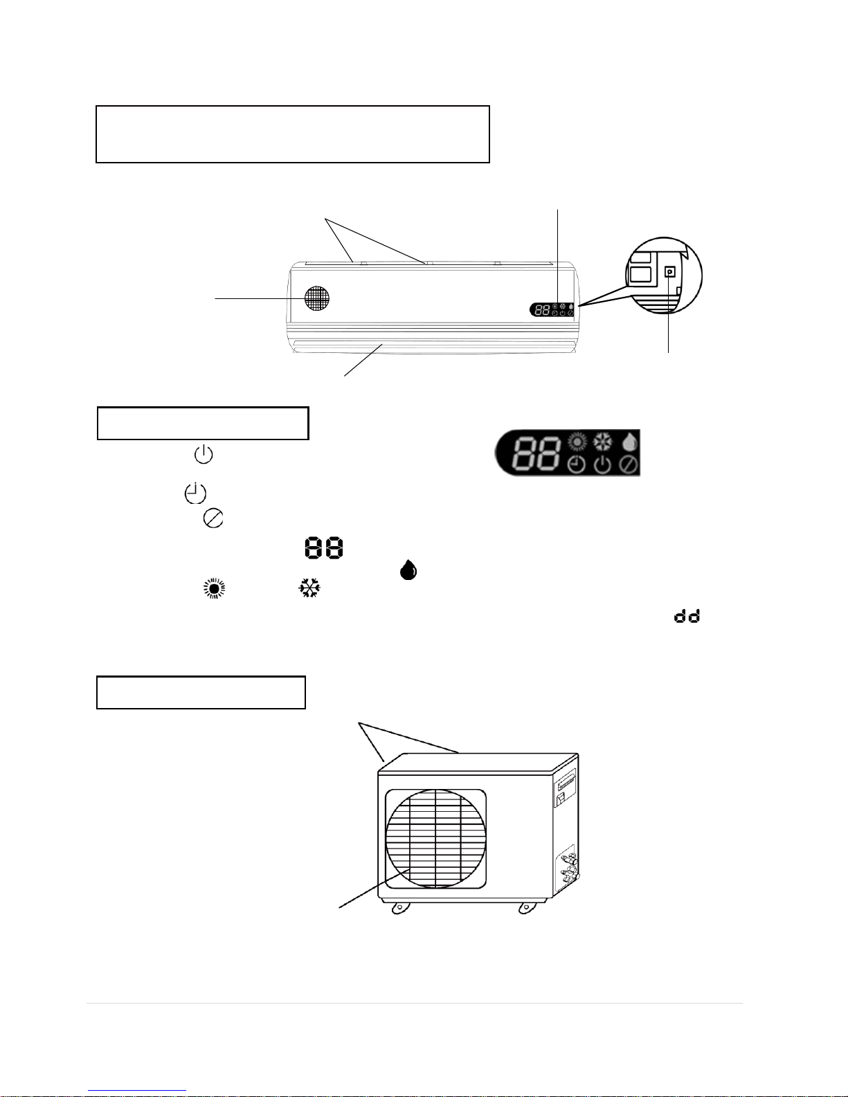
1.1 Indoor Unit
Intake vent
Digital Display
Air filter nets
Outlet vent
Emergency switch
Digital D
isplay
Running lamp on:The unit is operatonal
out:The unit is not running
Timer lamp on:Indicate the air conditioner is timed to on or off.
Protection lamp flash:Indicate the air conditioner is faulty, please call a serviceman.
Set temperature/Time display:
Mode display:
Heating / Cooling / Dehumidifying
Note:The unit displays the set temperature when it runs in cooling or heating mode and " "
when running in dehumidifying mode.
Note:Press "LOCK" button onceto turn the digital display off. Press it again to turn it back on.
1-2 Outdoor
Unit
Inlet
Outlet
Note: Your outdoor unit may have detail variations from this depiction
4 | P a g e
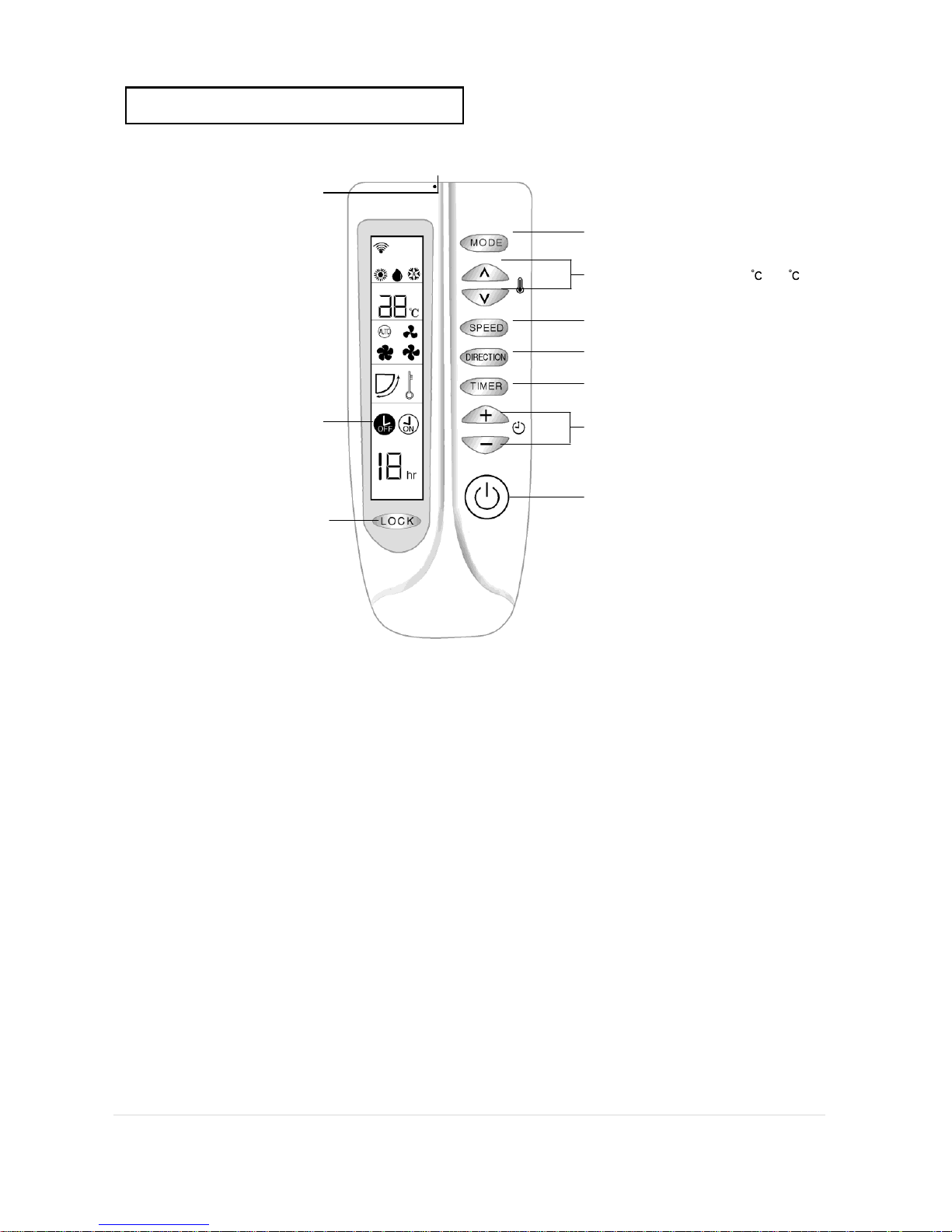
1-3
Remote
Controller
Display Section
Operation Section
Infrared transmitter
Transmits signal to indoor unit
Liquid crystal display
Lock key
Mode key
Choose cooling/dehumidifying/heating
Temperature setting key(16 J 30 )
Fan speed key
Choose Low/Medium/High/Auto
Air direction adjusting key
Timer key
Timer on/off/cancel
Time setting key (1-18hr)
Switch key
(on/off)
5 | P a g e
Directions:
Signal transmitting display:
Mode display: cooling dehumidifying heating
Temperature setting display:
Wind speed display : low medium high automatic
Air direction display: (Air direction adjusting)
Timer display:
Timer setting display: Lock display:
1. There may be differences between the temperature set by the remote control (The air
conditioner will stop working when the room reaches this temperature) and that measured by the
air conditioner. You can regulate the temperature you want by using the remote control.
2. The ability of the air-conditioner to reach the set temperature depends on the ambient
conditions in the room.
3. The displayed temperature on the remote controller is the set temperature.
4. The indoor fan has three speeds: high, low and breeze (breeze is set by the system
microcomputer automatically).
5. The remote controller should be aimed at the receiving window of the indoor fan unit which
will
send out a “beep” sound when the signal is
received.
2. Preparations before Operation
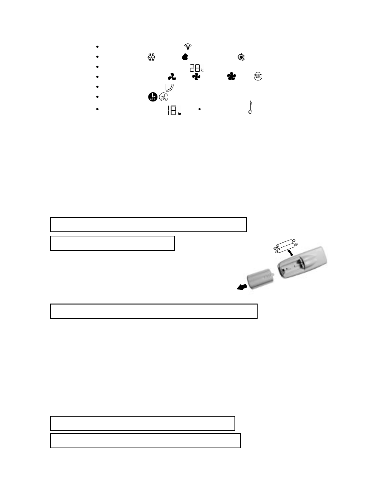
2-1 Usage of Batteries
1. Remove the back cover of the remote control by sliding in
the direction of the arrow.
2. Fi t two AAA size 1.5V batteries check the polarity.
3. Replace the back cover.
2-2 Operation of the Remote Controller
Aim the controller at the signal receiving window of the indoor unit.
There should be nothing between the remote controller and the signal receiving window.
Avoid violent bumping.
Avoid direct sunshine, heater and other heat resources.
The remote controller should be kept clean and dry.
Please use two AAA size 1.5V batteries with same brand.
The batteries should be taken out if the unit isn’t used for a long period of time.
Install two ne w batteries if the figures aren’t displayed clearly on the
LCD of the remote controller or the signal strength is low.
Always replace both batteries.
3. Operation Settings
3-1 Settings
6 | P a g e
Press “MODE” button and select “cooling” or “heating” mode, then press the temperature
setting button once, the pre-set temperature will be raised or lowered by 1 degree. .
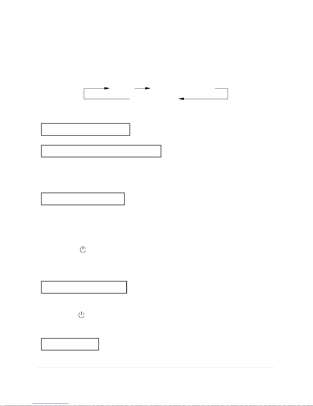
3-2 Air Direction Setting
Press the air “DIRECTION” button, the ventilating door will move as follows:
static up and down swing
close
Note: If you need a different static angle. Press “DIRECTION” button when the
louver is in the position you want.
3-3 Lock Operation
Press “LOCK” button to turn the display off, press again to return display to normal.
4.
Operation
of the Timer
In “cooling”, “dehumidifying” or “heating” mode, press “TIMER” button to select “timer off” or
“timer on”, then press “-” or “+” to set the time you need.
Note:
The initial setting of time is 1 hour.
The pre-setting time range is 1-18 hours.
5.
Running
Mode
5-1 Cooling
Press “MODE” button, select cooling mode.
Press pre-set temperature buttons, set the temperature you need.
Press “SPEED” button, choose the fan speed you need.
Press “DIRECTION.” button choose the air direction you want.
Stop, press “ ” button.
Attention: Before maintenance, keep the indoor unit running more than half an hour
(method: In cooling mode, set temperature at 20 ).
Note: When running lamp turns off this indicates the pre-set temperature has been
reached.
5-2 Dehumidifying
Press “MODE” button, choose dehumidifying mode.
Press “DIRECTION” button, choose the suitable air direction.
Stop, press “ ” button.
Note: 1. To dehumidify: Keep the outdoor unit running for 10 minutes, then stop for 5 minutes,
repeat in cycles, the fan speed of indoor unit should be at low speed.
2. The temperature can’t be pre-set when in dehumidifying mode.
5-3 Heating
Press “MODE” button, choose heating mode.
Press pre-set temperature buttons, set the temperature you need.
7 | P a g e
Press “SPEED” button, choose the fan speed you need.
Press “DIRECTION” button, choose the air direction you want.
To Stop, press “ ” button.
Note:
For details of indicating lamps see 1-4
5-4Emergency
Operation
Lift the front cover of the indoor unit ,and you will see the emergency switch(refer to1-1)
When Off, press the emergency switch button to operate the air conditioner, it will choose
cooling/dehumidifying/heating automatically depending on the indoor temperature.
When ON, press the emergency switch button to stop the system operating.
Note: This function can only be used when the remote control has been damaged or lost.
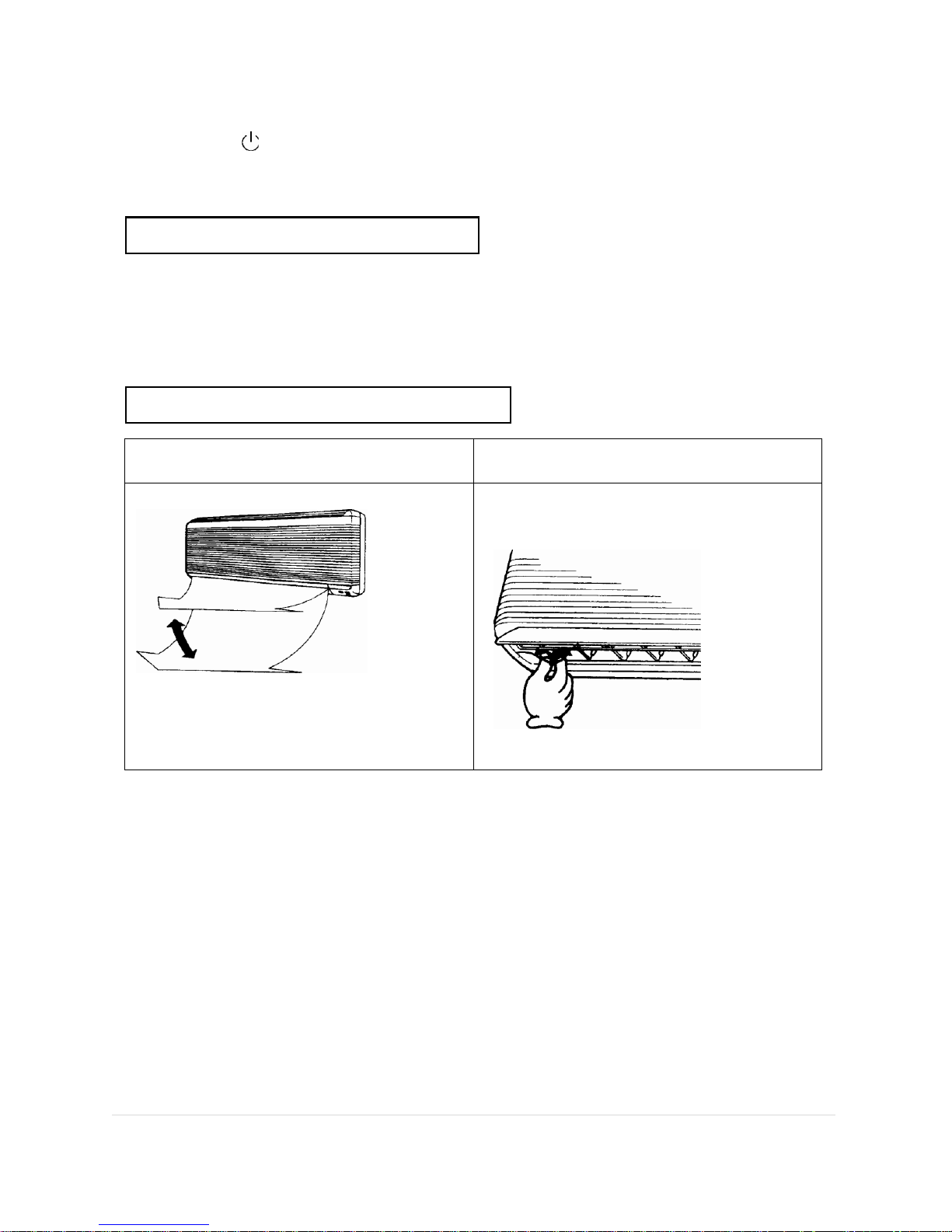
6.Air Direction
Control
6-1 Up and down air direction controlling
6-2 Left and right air direction controlling
The detailed operation see 3-3.
Regulate the left and right air direction by
moving the horizontal air direction guide
board by hand.
CAUTION
Please regulate up and down air direction by remote controller.
Don’t regulate the up and down air direction guide by hand when the unit is
running, or the link will be damaged.
Be careful when adjusting the left and right air direction because the fan runs
at high speed.
8 | P a g e
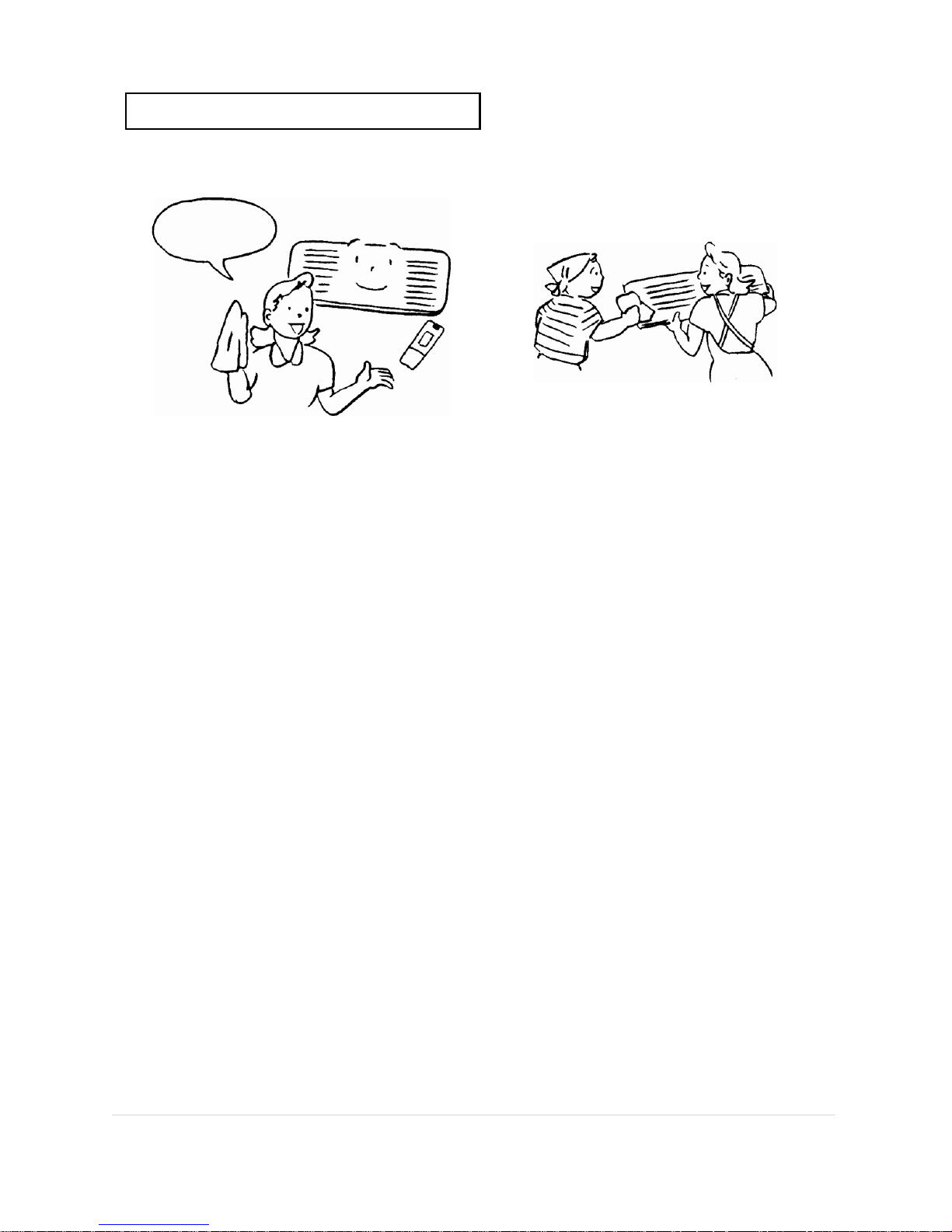
7.
Maintenance
Methods
Clean the remote controller Clean the intake vent grille
Use damp cloth with cold or warm water
under 40 degrees. Rub the unit gently.
Rub it with
soft cloth
Wash it gently with sponge and then dry.
If it is very dirty, use diluted detergent
solution.
9 | P a g e
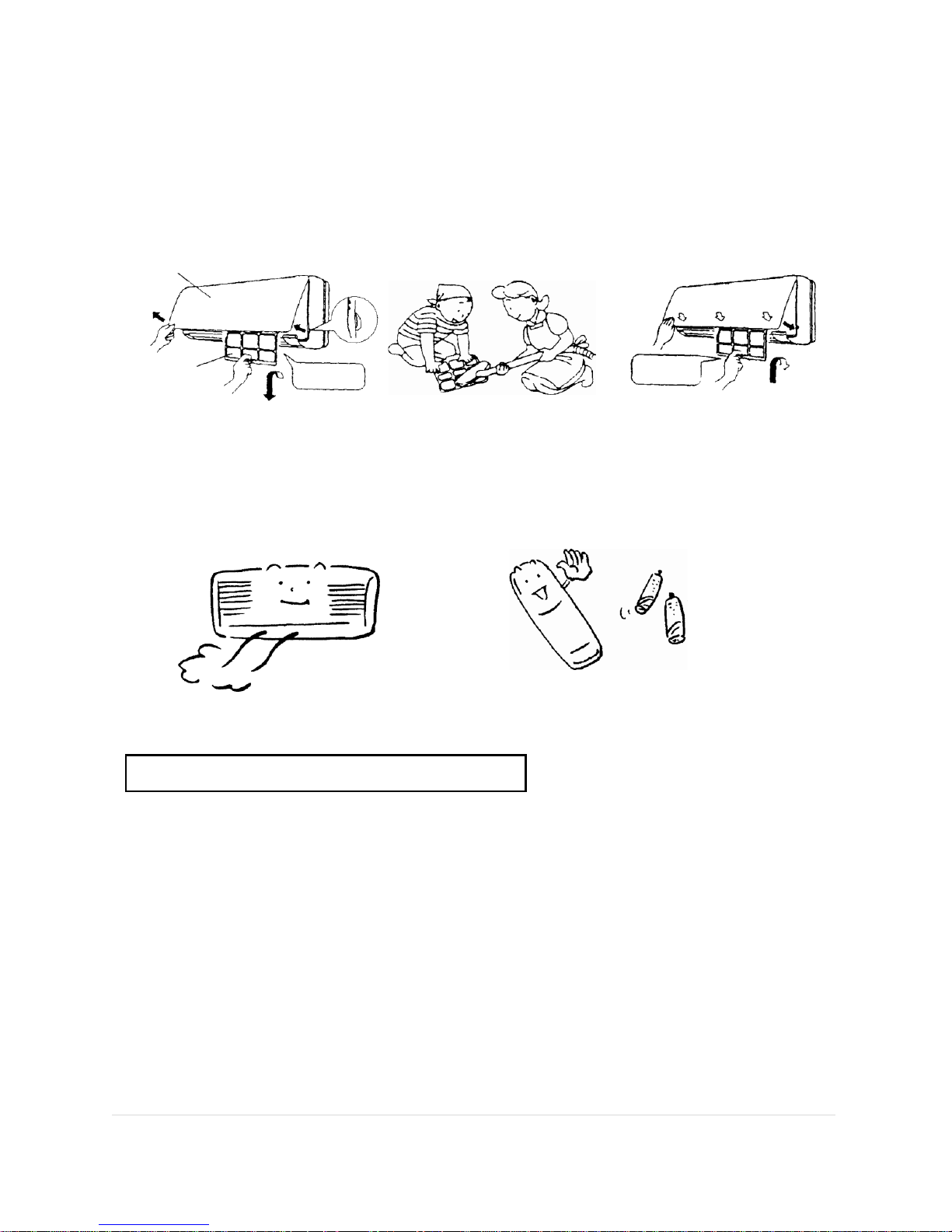
Clean the air filter (Recommended once every two weeks)
1. Hold the two ends of the
grille and pull it up-forward,
then draw out the air filters
downward gently (Do not
shake them, or the dust
will be released).
2. Use vacuum cleaner or
water to clean. Dry them
in shade after they have
been washed.
3. Hold the two ends of the
inlet grille, install the air
filters according to the
diagram, then shut the inlet
grille.
Inlet grille
Air filter net
Raise it then pull
it out downward
Raise it and install
it into the
groove
When the machine is not used for a long period of time:
Run it to dry the inside of
the machine.
Take out the batteries of
the remote controller.
Switch off the power.
8.
Operation Guide
In cooling mode, the temperature difference between indoor and outdoor should be within
5 degrees, for healthy living.
Try to prevent outdoor heat coming in (Close the doors and windows and pull drapes)
The air filters shouldn’t be blocked up, or they will lower the cooling efficiency.
Adjust the vertical and horizontal air direction for greatest comfort.
Do not let the cold air blow directly onto your body for a long period.
Raise the fan speed for greater cooling efficiency.
In heating operation, ensure the humidity of the room is monitored, or you will feel dry and
uncomfortable.
10 | P a g e
9.
Trouble
Shooting
Before calling a serviceman, please check the following:
Symptom
Possible reason
The air conditioner
does not work
The electrical plug is not in the socket.
The remote controller is not working.
The voltage is too low (Brown out).
The electricity was turned back on immediately after being cut off.
The voltage is irregular during stormy weather, please pull out
the plug, restart the unit in 3 minutes.
The compressor stops
working
In the drying operation, it works for 10 minutes, then stops for
5 minutes, repeats in cycles.
The room temperature has reached the temperarure set by
the remote controller.
In heating operation
the unit die not
produce warm air
The compressor is at delay stage (To protect the compressor,
there are several minutes delay for every start).
It has the ability to prevent cold air from blowing out,
please wait
for a moment after the compressor starts.
In defrost mode, hot air will be blown out automatically during
defrosting operation.
The efficiency of
cooling or heating is
low
The air filters are too dirty.
The intake vent or outlet vent is blocked.
In heating operation, the ambient temperature is too low.
Repeatedly heat and defrost.
Attention: The dirt between the fins of the outdoor heat exchanger should be cleaned regularly (cut off the power supply
before cleaning, be careful not to damage the cooling fins.)
Noise
Sounds like water flow?
-It is the sound of the circulation of refrigerant.
Sounds like air is condensed to leak out?
-In heating operation, at the beginning or end of defrosting,
this is the sound of the back-flow refrigerant.
Abnormality of the
remote controller
display
The power of the batteries has run out.
The batteries are inserted incorrectly.
Take out the batteries and insert them again.
Cold water leaks from
the air conditioner
Condensation will occur in the ai r outlet due to the temperature
difference.
11 | P a g e
System Specifications
.RROVROD(R)-26GW,.RROVROD(R)-26GW/A(R410a)
Item/Mode
.RROVROD(R)-26GW .RROVRODR)-26GW/A
Rated Cooling Capacity (W)
2600
2600
Rated Heating Capacity (W)
2900(Heat)
2900(Heat)
Rated Power Input (V/Hz)
220V/50Hz/60Hz
220V/50Hz/60Hz
Rated Cooling Power Input (W)
650~770
650~770
Rated Cooling Input Current (A)
2.95~3.50
2.95~3.50
Max Cooling Power Input (W)
962
962
Max Cooling Input Current (A)
4.38
4.38
Rated Heating Power Input (W)
650~780
650~780
Rated Heating Input Current (A)
2.95~3.55
2.95~3.55
Max Heating Power Input (W)
975
975
Max Heating Input Current (A)
4.44
4.44
Auxiliary Electric Heating
Rated Power Input (W)
600
600
Auxiliary Electric Heating
Rated Input Current (A)
2.73
2.73
Inhaling Max Working Pressure(MPa)
0.8
1.15
Exhausting Max Working Pressure
(MPa)
2.8
4.1
Amount of Added Refrigerant (kg)
850g
800g
Air Circulation of Outdoor Unit(m3/h)
450
450
Waterproof Grade
1PX4
1PX4
Net Weight (kg)
Outdoor unit
30
30
Indoor unit
8
8
Dimensions(mm)
length*width* height
Outdoor unit
790*260*540
790*260*540
Indoor unit
700*230*160
700*230*160
12 | P a g e
Noise Level dB(a)
Outdoor unit
<50
<50
Indoor unit
<40
<40
Note:
1.Parameters in the form are measured in the rated working state of GB/T7725-2004 (outdoor
temp 35℃DB/24℃WB; indoor temp27℃DB/19℃WB). Changes may appear according to the
real working state.
2. Parameters may change due to the product improvement. Please refer to the products
.RROVROD(R)-32GW, .RROVROD(R)-32GW/A (R410a)
Item/Mode
.RROVROD(R)-32GW .RROVROD(R)-32GW/A
Rated Cooling Capacity (W)
3200
3200
Rated Heating Capacity (W)
3500(Heat)
3500(Heat)
Rated Power Input (V/Hz)
220V/50Hz/60Hz
220V/50Hz/60Hz
Rated Cooling Power Input (W)
780~940
780~940
Rated Cooling Input Current (A)
3.55~4.27
3.55~4.27
Max Cooling Power Input (W)
1180
1180
Max Cooling Input Current (A)
5.33
5.33
Rated Heating Power Input (W)
780~950
780~950
Rated Heating Input Current (A)
3.55~4.31
3.55~4.31
Max Heating Power Input (W)
1190
1190
Max Heating Input Current (A)
5.39
5.39
Auxiliary Electric Heating Rated Power
Input (W)
800
800
Auxiliary Electric Heating
Rated Input Current (A)
3.63
3.63
Inhaling Max Working Pressure
(MPa)
0.8
1.15
Exhausting Max Working Pressure
(MPa)
2.8
4.1
Amount of Added Refrigerant (kg)
1000g
1000g
Air Circulation of Outdoor Unit(m3/h)
520
520

13 | P a g e
Waterproof Grade
1PX4
1PX4
Net Weight (kg)
Outdoor unit
38
38
Indoor unit
10.5
10.5
Dimensions(mm)
length*width* height
Outdoor unit
790*260*540
790*260*540
Indoor unit
785*285*210
785*285*210
Noise Level dB(a)
Outdoor unit
<50
<50
Indoor unit
<42
<42
Note:
1.Parameters in the form are measured in the rated working state of GB/T7725-2004 (outdoor
temp 35℃DB/24℃WB; indoor temp27℃DB/19℃WB). Changes may appear according to the
real working state.
2. Parameters may change due to the product improvement. Please refer to the products
.RROVROD(R)-35GW, .RROVROD(R)-35GW/A(R410a)
Item/Mode
.RROVROD(R)-35GW .RROVROD(R)-35GW/A
Rated Cooling Capacity (W)
3500
3500
Rated Heating Capacity (W)
3800(Heat)
3800(Heat)
Rated Power Input (V/Hz)
220v/50Hz/60Hz
220v/50Hz/60Hz
Rated Cooling Power Input (W)
800~1025
800~1025
Rated Cooling Input Current (A)
3.64~4.66
3.64~4.66
Max Cooling Power Input (W)
1280
1280
Max Cooling Input Current (A)
5.83
5.83
Rated Heating Power Input (W)
800~1050
800~1050
Rated Heating Input Current (A)
3.64~4.77
3.64~4.77
Max Heating Power
Input of Heat Pump (W)
1310
1310
Max Input Current of
Heat Pump (A)
5.96
5.96

14 | P a g e
Auxiliary Electric Heating
Rated Power Input (W)
800
800
Auxiliary Electric Heating
Rated Input Current (A)
3.63
3.63
Inhaling Maximum
Working Pressure(MPa)
0.8
1.15
Exhausting Maximum
Working Pressure(MPa)
2.8
4.1
Amount of Added Refrigerant (kg)
1300g
1150g
Air Circulation of Outdoor Unit(m3/h)
550
550
Waterproof Grade
1PX4
1PX4
Net Weight (kg)
Outdoor unit
38
38
Indoor unit
10.5
10.5
Dimensions(mm)
length*width* height
Outdoor unit
790*260*540
790*260*540
Indoor unit
785*285*210
785*285*210
Noise Level dB(a)
Outdoor unit
<52
<52
Indoor unit
<42
<42
Note:
1.Parameters in the form are measured in the rated working state of GB/T7725-2004 (outdoor
temp 35℃DB/24℃WB; indoor temp27℃DB/19℃WB). Changes may appear according to the
real working state.
2. Parameters may change due to the product improvement. Please refer to the products
.RROVROD(R)-60GW,.RROVROD(R)-60GW/A(R410a)
Item/Mode
.RROVROD(R)-60GW .RROVROD(R)-60GW/A
Rated Cooling Capacity (W)
6000
6000
Rated Heating Capacity (W)
6600(Heat)
6600(Heat)
Rated Power Input (V/Hz)
220V/50Hz/60Hz
220V/50Hz/60Hz
Rated Cooling Power Input (W)
1350~1560
1350~1560

15 | P a g e
Rated Cooling Input Current (A)
6.14~7.09
6.14~7.09
Max Cooling Power Input (W)
1950
1950
Max Cooling Input Current (A)
8.86
8.86
Rated Heating Power Input (W)
1350~1590
1350~1590
Rated Heating Input Current (A)
6.14~7.23
6.14~7.23
Max Heating Power Input (W)
2000
2000
Max Heating Input Current (A)
9
9
Auxiliary Electric Heating
Rated Power Input (W)
1500
1500
Auxiliary Electric Heating
Rated Input Current (A)
8.1
8.1
Inhaling Max Working Pressure(MPa)
0.8
1.15
Exhausting Max Working Pressure
(MPa)
2.8
4.1
Amount of Added Refrigerant (kg)
1700g
1600g
Air Circulation of Outdoor Unit(m3/h)
850
850
Waterproof Grade
1PX4
1PX4
Net Weight (kg)
Outdoor unit
55
55
Indoor unit
21
21
Dimensions(mm)
length*width* height
Outdoor unit
940*300*755
940*300*755
Indoor unit
985*325*230
985*325*230
Noise Level dB(a)
Outdoor unit
<56
<56
Indoor unit
<46
<46
Note:1. Parameters in the form are measured in the rated working state of GB/T7725-2004
(outdoor temp 35℃DB/24℃WB; indoor temp27℃DB/19℃WB). Changes may appear according
to the real working state.
2. Parameters may change due to the product improvement. Please refer to the products

16 | P a g e
.RROVROD(R)-72GW, .RROVROD(R)-72GW/A(R410a)
Item/Mode
.RROVROD(R)-72GW .RROVROD(R)-72GW/A
Rated Cooling Capacity (W)
7200
7200
Rated Heating Capacity (W)
7900(Heat)
7900(Heat)
Rated Power Input (V/Hz)
220/50Hz/60Hz
220/50Hz/60Hz
Rated Cooling Power Input (W)
1700~1900
1700~1900
Rated Cooling Input Current (A)
7.73~8.64
7.73~8.64
Max Cooling Power Input (W)
2375
2375
Max Cooling Input Current (A)
10.8
10.8
Rated Heating Power Input (W)
1700~1950
1700~1950
Rated Heating Input Current (A)
7.73~8.64
7.73~8.64
Max Heating Power Input (W)
2440
2440
Max Heating Input Current (A)
10.8
10.8
Auxiliary Electric Heating
Rated Power Input (W)
1800
1800
Auxiliary Electric Heating
Rated Input Current (A)
8.18
8.18
Inhaling Max Working Pressure(MPa)
0.8
1.15
Exhausting Max Working Pressure
(MPa)
2.8
4.1
Amount of Added Refrigerant (kg)
1950g
1800g
Air Circulation of Outdoor Unit(m3/h)
1050
1050
Waterproof Grade
1PX4
1PX4
Net Weight (kg)
Outdoor unit
62
62
Indoor unit
19
19
Dimensions(mm)
Outdoor unit
940*300*755
940*300*755

17 | P a g e
length*width* height
Indoor unit
985*325*230
985*325*230
Noise Level dB(a)
Outdoor unit
<54
<54
Indoor unit
<42
<42
Note:1. Parameters in the form are measured in the rated working state of GB/T7725-2004
(outdoor temp 35℃DB/24℃WB; indoor temp27℃DB/19℃WB). Changes may appear according
to the real working state.
2. Parameters may change due to the product improvement. Please refer to the products

18 | P a g e
Safety Notice
Safety Warning:
Install the electrical switch for the solar air conditioner out of the reach of children in order
to prevent electrocution.
Please switch off the power in the event of stormy weather; otherwise lightning may
damage the machine.
Please switch off the power when the machine is not in use for long periods.
Please switch off the power before cleaning or maintaining the machine.
Never clean the machine with liquid detergent, liquefied cleaning agent, or corrosive
cleaning agent. Never sprinkle water or other liquid on the machine. Liquid could damage
the plastic accessories or electric shock may occur.
△ Danger:
Never put your hands or a stick into the air outlet of the indoor or outdoor machine.
Never touch the air deflectors when the system is running.
Never remove the cover of the machine, as the high-speed fan could cause injury.
Never allow children to play with the solar air conditioner.
Never wet the indoor fan head or the remote controller. Otherwise it may cause an
electrical short circuit.
Never put or use combustible liquid or gas such as hair styling jell, paint, or gasoline near
the machine. Otherwise it may ignite.
If some unusual condition occurs, such as noise, smell, smoke, temperature increase,
please cut off the power immediately. Call the local distributor or solar air conditioner after-
sales service centers. Do not attempt to repair the machine yourself.

19 | P a g e
Solar Air Conditioner Application
Check the following before use:
*Please ensure that the earth wire is connected.
*Please ensure that the air cleaner is washed.
*If the solar air conditioner is idle for a long period, please clean the air cleaner before use. For
more details, please consult the chapter
Repair and Maintenance
.
*The inlet and outlet openings of the indoor and the outdoor units should be unrestricted.
Optimum operation
*Please set a sensible temperature (e.g. In Australia 24
O
C is recommended as a good balance
between comfort and energy efficiency). Avoid excessively hot or cold temperatures, especially
with the elderly, children and invalids.
* When cooling, please use curtains or shutters to reduce the effect of direct sunlight.
*Please close all windows as the convection of indoor and outdoor air will decrease the
efficiency of the system.
*If you need to set the pre-runtime, please use the remote controller.
*Never place barriers, which block the airflow, near the indoor and outdoor units. It will decrease
the effectiveness or even damage the air conditioner system.
*Please clean the air cleaner frequently. If the air cleaner is blocked, it decreases the efficiency
of the system.

20 | P a g e
Working temperature range
Mode
Temperature
Cooling
Heating
Indoor Temperature
above 18
o
C
below 31
o
C
Outdoor Temperature
18
o
C ~53
o
C
-7
o
C ~24
o
C
To ensuring normal operation of the Koolsola solar air conditioner, please use it in the
recommended working temperature range.
Repair and Maintenance
Please turn off the electricity before performing any repairs or
maintenance.
1.Check The fluid Level in the solar panel periodically and
Before Starting Up.
(1)Remove the filler cap on the thermal storage tank.
(2)Add water if required to reach correct level.
(3)Please contact the local distributor or service center if unsure.
2.Rinse the Air Filter
1)Remove the filter
(a)Please open the front grill by lifting upwards.
(b)Extract the two air filter screens by pulling
downwards.
2)Rinse the air filter screen
(a)Clean the filter screen with a vacuum cleaner.
(b)Wash the filter screens with clean warm water
below 40℃.
3)Reinstall the filter screens after airing.
4)Close the inlet grill of the indoor unit.
﹡Please rinse the filter screen every 15 days.

21 | P a g e
3.
Clean the Outer Surface of the Solar Air Conditioner
①Wipe the outer surface with a soft cloth and clean water.
②Wipe the outer surface with soft cloth.
Attention:
①Hot water above 40℃ may cause deformation or discoloration to the solar air conditioner’ s
surface.
②Volatile liquid such as thinner or gas, may damage the color of the solar air conditioner’ s
surface.
4.Inspection during Season Changes
1) When the air conditioner has not operated for a long time
a) Please switch on the air conditioner in cooling mode during fine weather. The moisture inside
will be eliminated over 6 to 8 hours.
b) Please switch off the solar air conditioner by the remote controller, cut off the electricity, and
take out the batteries in the remote controller.
c) Clean the outdoor unit, and wrap it with a plastic film cover.
2) Air conditioner inspection before starting up during season changes
①Take off the plastic protection cover of the outdoor unit.
②Check the power circuit and connecting wire to ensure there is no damage.
③Make sure that there is no constriction in the outlets of the indoor unit or the outdoor unit.
④The drainpipe is not damaged.
⑤Rinse the filter screens and reinstall them. Switch on the air conditioner for half an hour.
5.Attention
a)Never place inflammables or explosive goods such as paint, shampoo, etc near the air
conditioner.
b)Never use the air conditioner for drying clothes or food preservation.
c)Keep other heat sources away from the solar air conditioner.
d)If the wiring is damaged, please turn off the electricity and call serviceman for repair in order to
avoid an accident.
e)Install an individual circuit breaker for the source wire of the air conditioner. The rated current
of the circuit breaker should be 15A. The copper core section area of the electric power
conductor is at least 2.5mm2.

22 | P a g e
Common Faults and Solutions
If your solar air conditioner does not operate normally, please check the following items before
maintenance. If the problem cannot be identified, please contact our Repair Center or the
distributor.
Problem
Possible Reason
Solution
Out of operation
1.Power failure
2. The circuit breaker tripping
3. The voltage is exceedingly low.
4. The air conditioner special fuse is burnt out.
5. The air conditioner is switched off as a
result of misuse of the timer
6. The air conditioner is in defrosting mode.
1.Re-connect the power supply
2.Contact the repair center
3. Consult the electrician or distributor.
4. Change the fuse or consult the after service center.
5.Cancel the timing and reboot
6. Please wait for a moment.
Poor cooling and
heating effect
1.The filters are dirty or blocked
2.A heating source or many people are
indoors
3. The temperature setting is incorrect.
4. The air inlet and air outlet of the indoor
machine are blocked.
5. The window or the door is open.
6. Outdoor temperature is below 0℃ while
heating.
7. The liquid is insufficient in the insulated
tank.
1.Clean filters to improve air flow
2. Remove the heating source if possible. (Please pay
attention to the air conditioner type when purchasing.)
3. Reset the temperature.
4.Remove the obstacles to ensure proper airflow
5. Close the door and window to avoid cooling air or
heating air from escaping.
6. Use additional heating to supplement air conditioner
7. Top up the tank.
Noise is aloud
1.Water flow sound
2.Exhausting sound
3. System is unstable.
4. The operation noise is obviously unusual.
1. Cooling fluid is flowing in the machine when the air
conditioner switches on and switches off. Please wait for a
moment.
2. This is the sound of the four way valve switching. Please
wait for a moment.
3. Please contact the distributor
4. If any unusual noise is heard, please contact the repair
center.
Compressor does
not work.
1. The temperature setting is incorrect.
2. The LCD shows that the timing is ‘ on’ .
3. For protection, the compressor will not work
in the first 3 minutes. Please wait for a
moment.
1. Reset the temperature.
2. Cancel the timing and then reboot.
3. It is a normal phenomenon. Please wait for a moment.

23 | P a g e
No immediate
wind blows out
during heating.
If the air conditioner blows when the
evaporator is at a low temperature, the wind
will be uncomfortable. Please wait till the
evaporator is heated.
Please wait for a moment.
The compressor
starts and stops
frequently.
1. The input voltage is exceedingly low.
2. Too many appliances are applied on the
same line. The voltage for the air conditioner
is insufficient.
3. The insulation of the room is poor.
1. Check the electric power source (voltage and wire
diameter).
2. Wire the system to an individual circuit breaker.
3. Improve the insulation of the room.
The display of
remote controller
is not clear or not
working
1. The batteries are dead.
2. Batteries are installed back to front.
1.Replace with new alkaline batteries
2.Install the batteries correctly
Common Faults Diagnosis and Elimination
Non-failure Conditions
1. When you turn on or turn off the solar air conditioner, sometimes you will hear sizzle sound,
which is the flowing sound of the cooling agent, and is not a malfunction.
2. The solar air conditioner cannot restart at once after it stops, even though it is switched on.
Within 3 minutes, the compressor will not run in cooling, dehumidifying or heating modes.
3. Sometimes, the solar air conditioner absorbs stale air. This collects in the filters. Under such
conditions, there is no problem with the solar air conditioner. The filter screen needs cleaning.
4. When heating, the indoor machine and the outdoor machine may stop simultaneously, but the
compressor still runs. It is on defrosting mode. The heating performance will continue after
defrosting has finished.
5. When heating, the outdoor machine may generate condensation. This is a result of defrosting
and thawing, and is not a malfunction.
How to Save Energy:
Never block the air inlet and the air outlet of the solar air conditioner. The air conditioner will not
run normally and may be damaged if the outlets are obstructed. When cooling, please avoid
direct sun radiation into the room. Please pull curtains or shutters. If the walls and ceiling of the
room are not insulated the cost of cooling will be greater. Please keep the air filter clean.
Blocking of the filter screen will greatly reduce the efficiency of the air conditioner. Keep the
window, door and any openings closed, so as to avoid cooling air escaping.

24 | P a g e
Failure Display Status List
.RROVROD-26GW, .RROVROD-32GW,.RROVROD-35GW, “ B” type
Failure Type
Display Status
Indoor Temperature Sensor Failure
E1
Indoor Cooler Transmitter Failure
E2
System Failure
E4
.RROVROD-60GW, .RROVROD-72GW, “ D” type
.RROVROD-26GW, Koolsola-32GW, Koolsola-35GW, “ HC” type
Failure Type
Display Status
Indoor Temperature Sensor Failure
Light shines 1time/8seconds
Indoor Cooler Transmitter Failure
Light shines 2times/8seconds
System Failure
Light shines 4times/8seconds
If any of these failures occur, please contact the distributor or the service centre.
Solar Air-conditioner Installation
The Installation Guide
Warning: Solar air conditioner must be installed by an approved installer. Do not install by
yourself as warranty will be void. In order to install it correctly, please first read the content of
‘ Installation Part’ . The installation of this solar air conditioner should be in accordance with
the standards of
GB17790 National Standard Room Air Conditioners Installation Guidelines
and
the requirements of this instruction booklet.
After installation, the installer should advise the user how to use and maintain the air
conditioner; ask the user to read carefully and to take care of the
‘ installation and application
instruction
’ .
Installation Notice:
Installing the air conditioner in the following places may cause malfunctions. If this can not be
avoided, please contact the after sale service centre.

25 | P a g e
① Places where the air contains oil (lubricating oil).
② Places where the air contains sulfide gas (sulfide hot spring).
③ Places where the air contains inflammable or volatile gas.
④ Seashore alkaline land.
⑤ Places where high frequency equipment are operated, such as wireless apparatus, welding
apparatus, and medical equipment.
Electrical work
Electrical work should conform to the Standards of the
GB17790 National Standard Room Air
Conditioners Installation Guidelines
⊙Electric appliance security requirements during the first installation
1. If the user’ s electricity supply is dangerous, the installer should refuse to install and explain
clearly. Only after the danger is removed should the installation continue.
2. Fluctuation of line voltage is usually between +10%, if the voltage is not in this range, please
take measures to regulate it.
3. An earth leakage protector and a master switch should be provided on the line. A separate
circuit breaker should be supplied. Please select the appropriate circuit breaker according to the
rate of the electric power consumption, which comprises 1.5 to 3 times of the maximum current
of the solar air conditioner and the current of other electric appliances on the same circuit.
4. The power cord should be provided with an effective earth wire. If not, the installer should
refuse to install and clearly explain.
5. The power source must be supplied only for the solar air conditioner and should satisfy the
following items.
Form 5. Comparison of the Standards of Electric Conductor Cross Section Area (Diameter of
Wire), Power Switch, Fuse and Load Current
Special power distribution equipment and electric
wire for solar air conditioner
Power distribution equipment and electric
wire for the power bus
Air
conditioner’ s
maximum
current (A)
Electric
conductor’ s
cross-sectional
area(mm2)
Standard
spec (A) of
the socket or
power of the
switch /fuse.
Circuit’ s
maximum
current×(1.5
to 3 times)
(A)
Electric
conductor’ s
cross sectional
area(mm2)
Standard
spec (A) of
the power
switch / the
fuse
≦10
1 or 1.5
16/16
≦16
1.5~4
32/25
≦16
1.5 or 2.5
32/25
≦25
2.5~4
63/50
≦25
2.5 or 4
63/50
≦32
4~10
63/50
≦32
4 or 6
63/50
≦40
6~16
100/80
≦63
10~25
125/125

26 | P a g e
Notice: The maximal electric current of the solar air conditioner refers to the maximal input
electric current, which is printed on the brand of the indoor unit. The maximum electric current of
the circuit refers to the total summation the maximal electric current of the solar air-conditioner
and the maximal electric current of other appliances on the same circuit.
The electric security requirement of installation of solar air conditioner
1. Power cord of indoor and outdoor units must not be polyvinyl chloride, and must be
chloroprene rubber wires (including high-tension signal wires). It is forbidden to lengthen or
shorten the wires by yourself. The exceedingly long wire of electric source should be folded as
large round curves. It is strictly forbidden to wind wires into small circles.
2. The earth wire must be yellow and green wire with adequate wire size. The earth wire is
strictly prohibited to connect to pipe of tap water, pipe of coal gas, zero line of electric source,
and overhead ground wire.
3. When you connect wires, please refer to the electric circuit diagram in the machine and
ensure everything is correct.
Please install the air conditioner at a place, which is provided with the following characteristics.

27 | P a g e
1)Indoor Unit
① Indoor unit should be installed upon a firm vibrationless wall.
② Entrance and vent are supposed to be open and not restricted. The hot and cool air
should blow toward the centre of the room.
③ Indoor unit should be installed where it is convenient to connect with the outdoor unit.
④ Indoor unit Installation should avoid direct solar radiation.
⑤ Indoor unit should be installed where drainage is convenient.
⑥ Indoor unit Installation should give consideration for future maintenance.
⑦ The filter screen should be accessible. Indoor unit Installation should ensure the spaces
which are shown in the following picture.
2)Outdoor Unit
* Outdoor unit should be installed on a solid, level foundation with rubber feet, otherwise
noise and vibration will increase.
* Please ensure that nothing blocks the vent.
* At the seaside, please do not install the outdoor unit at a high altitude where the sea wind
is more forceful. To ensure the fan works normally, the solar air conditioner should be arranged
tightly upon the wall. A baffle is to be used.
* Prevent wind blowing to the inside of the solar air conditioner, especially in places where
the wind is particularly strong.
* Any barriers, which may block heat from dissipating, should be removed.
* If you use hanging installation, the wall should be composed of solid brick, concrete, or
other equally firm structure. Otherwise, please reinforce, stabilize, and secure the solar air
conditioner installation.
* Design and manufacture of mounting frame should take consideration of bearing capacity
The ceiling
More than 40 cm
More than 20cm
More than 20cm
Hanging plate
Left
Right

28 | P a g e
of material and structure, corrosion resistance, and convenience for installation and
maintenance. The strength of outdoor erecting frame should be able to endure weight
above180kg. Steel components must be joined firmly, use anticorrosive treatment, and satisfy
the standards of the
GB17790-1999 National Standard Room Air Conditioners Installation
Guidelines
* The foot screws of outdoor unit should be fixed with M8 or M10 bolts.
1 Outdoor unit should be installed on a solid foundation with rubber feet secured to the
foundation.
2 The unit should be installed vertically and horizontally, the gradient must be below 5°.
3 Outdoor unit installation should avoid places where water drops directly on the unit, and which
is near thermal spring with sulphur or nitrogen gas.
4 Indoor unit installation should ensure the space distance shown on the picture below.
Installation of the Solar Air Conditioner
2. Indoor Unit Installation
1) As shown in the following picture, pipelines are connected in five directions from the indoor
unit. When the pipelines are connected in ③ or ④ direction, please use a saw to open a
preformed groove on the panel. When the pipelines are
connected in ⑤ direction, please use the saw to open a
preformed groove under the panel.
2) Use five 5Y51 size wood bolts to fix the board on the wall
Notice:
* If indoor unit is installed on a concrete wall, please use expanding bolts.
* When you install the board, ensure it is level horizontal or vertical.
* The installed board should be able to bear 50 kg.
* Ensure that the board is firm and solid.
3) Based on the junction direction of the pipeline (Please consult the following picture), a hole
which is provided with the diameter of 65 mm, is drilled in the corresponding place on the
wall. Then the wall bushing and the tube cap are placed into the hole. If the pipeline is
connected in the ③ or ④ direction, the hole in the ③ or ④ should be opened a little lower
①Back
③Left
⑤down
②Left-back
④Right
Plumb-line
Wood bolt
The board

29 | P a g e
than the height of the hole in the ①or ②.The aim is to ensure the condensate flows out of
the pipe.
Installation of the Solar Air Conditioner
4) Please install the pipe of the indoor unit according to the direction of the wall hole; the outflow
pipe, the cable line, and the indoor unit should be bundled with adhesive tape. The outflow pipe
is below the other two.
5) Lead the taped pipes through the wall bushing, and hang up the indoor unit on the top hooks,
the bottom long channels of the indoor unit are shown in the following picture.
Left exit
Less low
Center
The board
Center
Right exit
Outdoor side
Indoor side
Wall
Pipe through the wall
Pipe cover
About 5-7 mm

30 | P a g e
3. Installation of the solar collector
Flat plate type collector
1) Adjust the distance between outdoor unit and the panel. (piping is only 1m) Make sure they
are able to connect by pipes later.
2) Screw the two brackets on the bottom to the wall. Adjust the position of the upper 2 brackets;
screw them to the wall too
3) Place the panel inside the brackets from the top.
4) Link the short PP pipe to the panel, input water from it till water comes out from the small hole
on it. Then put the air vent cap on it.
5) Connect the PVC pipe to the PP pipe, which is from indoor unit condensation
6)Connect the panel to the outdoor unit by 2 copper pipes (1m)
B-1
B-2

31 | P a g e
B-3
B-4

32 | P a g e
Solar Air Conditioner Installation
4. Condensate Tube
1) Connect one end of the outflow
extended pipe to the outflow pipe
head of the indoor unit. (As shown
in the following picture)
2) Release the nitrogen filled in the radiator of the indoor unit when the air conditioner leaves the
factory. Remove the cover cap of the thick connecting pipe and the cover cap of the thin
connecting pipe of the radiator.
3) Take out the two connecting pipes
carefully, remove the cover caps of the
pipes and connect them to the stop
valve A1 and A2. (As shown in the
following picture)
4) Remove the caps of the two connecting
pipes, and tighten the nuts of the low
pressure and the high pressure connecting
pipes (As shown in the following picture)
5) Remove the caps on the stop valves of the low pressure and the high pressure connecting
pipes, screw one end of the thick connecting pipe and one end of the thin connecting pipe on
the stop valves of the low pressure and the high pressure connecting pipes, and tighten the nuts
of the thick and thin connecting pipes using a spanner. (As shown in the following picture)

33 | P a g e
Solar Air Conditioner Installation
5. Pressure test with Nitrogen for leaks.
6. Vac down the solar panel tank and indoor unit completely to below 900microns for as long as
possible (recommend 1 hour min.)
If air, water or other impurities, enter the solar air conditioner system, it will cause excessive
working current, capillary blockage etc. which will affect the performance of the air conditioner.
Ensure complete elimination of air, water and other impurities in the cooling pipe of solar tank
and side tube of indoor unit.
Pipe size for solar panel loop is 3/8”
Air Pipe
Stud type copper sealing attachment

34 | P a g e
Empty the solar tank
Please follow the instructions to eliminate the air in the solar tank.
(As shown in the picture)
①Please use a spanner to remove the A1 and the A2 cut-off valve caps of the outdoor unit.
②Please use a spanner to loosen the stud type copper sealing attachment half a circle upon the
air pipe of A1cut-off valve.
③Please use an inner hexagonal wrench to loosen the center of A2cut-off valve for 90°. After 7
to 11 seconds, fasten up the A2 cut-off valve. Air is exhausted from A1 air stud type copper
sealing attachment. When there is no air escaping, according to the moment from 20 to 25N·M,
please fasten the stud type copper sealing attachment.
④Please use the inner hexagonal wrench to open the A1 and A2 cut-off valve cores.
⑤Please fasten A1 and A2 cut-off valve caps.
⑥Please use soapy water or halogen detection instrument to detect leakage. If you find
leakage, you need to fasten A1 and A2 cut-off valve caps. And then you can introduce
refrigerant from outside of the system to expel air.
Empty the connecting pipe of the indoor unit
Please follow the instruction to eliminate the air in the solar tank.
(As shown in the picture)
① Please use a spanner to remove the B1 and the B2 cut-off valve caps of the outdoor unit
② Please use a spanner to loosen the stud type copper sealing attachment half a circle upon
the air pipe of B2cut-off valve.
③ Please use the inner hexagonal wrench to loosen the centre of B1 cut-off valve by 90°. After
7 to 11 seconds, fasten up the B1 cut-off valve. Air is exhausted from B2 air stud type
copper sealing attachment. When there is no air escaping, according to the moment from
20 to 25N·M, please fasten the stud type copper sealing attachment.
④ Please use inner hexagonal wrench to open the of B1 and B2 cut-off valve cores.
⑤ Please fasten B1 and B2 cut-off valve caps.
⑥ Please use soapy water or halogen detection instrument to detect leakage. If you find
leakage, you need to fasten B1 and B2 cut-off valve caps. And then you can use refrigerant gas
from outside of the system to expel air.

35 | P a g e
S
olar Air Conditioner Installation
The length of piping and freon
① When the pipe line is extended, discharge the air in the connecting pipe with refrigerant gas,
which is from the outside of the system. And then, discharge the redundant refrigerant in
degassing method.
②Installation height of the indoor unit and the outdoor unit should be below
5 m.
③The length of the pipe, which connects the indoor unit and the outdoor
unit, should be less than 8m for systems up to Koolsola-60GW and
Koolsola-72GW shall be less than 10m otherwise more refr
igerant
must be added.
④ The refrigerant filling amount of the solar air conditioner should be
adjusted according to the length of the pipe (L). The refrigerant increment
G= (L- length of the extra pipe)*N (g/m).
After Freon added, please check the inhaling maximum working pressure with the parameters.
Model N
KoolsolaE-26GW 35g
Koolsola-32GW 45g
Koolsola-35GW 50g
Koolsola-60GW 70g
Koolsola-72GW 100g
Air Pipe
copper sealing attachment

36 | P a g e
Connection of the Power Supply of the Outdoor Units
Dismount the outlet box of the outdoor unit; connect the
triple core wire and the twin core wire with the five jacks of
the connecting terminals in accordance with their colours. As
shown in the following form, the connection method of the
triple core wire of the subsidiary electric heating pipe on the
solar panel is that the blue wire is connected with terminal
board 4 (N), the red wire is connected with terminal board 3; the yellow/green wires are
connected with terminal board grounded.
The Terminal Board Base on the
Outdoor Units
1 2 3
4(N)
The Color of Wire Connected With
the Indoor Unit
Brown
Yellow
Red
Blue
Yellow/Green
Connecting with the Auxiliary
Electric Heating Tank
Red
Blue
Yellow/Green
-

37 | P a g e
Circuit Diagram of the Solar Air Conditioner
K
oolsola26GW Koolsola35GW Koolsola60GW Koolsola72GW (Cooling)
Koolsola26GW Koolsola35GW Koolsola60GW Koolsola72GW (Cooling and Heating)

38 | P a g e
K
oolsola26GW Koolsola35GW Koolsola60GW Koolsola72GW (Cooling)
Koolsola26GW Koolsola35GW Koolsola Koolsola60GW 72GW (Cooling and Heating)

39 | P a g e
Packing List
Solar Collector Packing List
Flat Plate Type
No.
Name
Quantity
1
collector
1pc
2
Connecting pipe
2pcs
3
Brackets
4pc 4 PVC pipe
1pc
5
Ventilation Cap Groupware
1pc
6
Plastic water outlet pipe
1pc
Indoor Unit Packing List
No.
Name
Quantity
1
Indoor Unit
1pc
2
Application and Installation manual
1pc 3 Remote Controller
1pc
4
Standard AAA Battery
2pc
5
bracket
1pc
50g6
Rubber mud
1pc 7 Expansion screw
5pcs
8
Screw
5pcs

40 | P a g e
Outdoor Unit Packing List
TKF(R)-26GW, TKF(R)-32GW, TKF(R)-35GW, TKF(R)-60GW,
No.
Name
Spec
Quantity
Outdoor Unit
/
1
2
Low Voltage Connecting Pipe
TP2MФ12.7*0.7*3600mm
1
3
High Voltage Connecting Pipe
TP2MФ6.35*0.7*3600mm
1
4
Plastic Belting
T8*20m
2
5
Penetration
ABSФ60mm
1
6
draining pipe
PVC
1
7
Joint #6 (cool&heat type)
PVC
1
TKF(R)-72GW
No.
Name
Spec
Quantity
1
Outdoor Unit
/ 1 2
Low Voltage Connecting Pipe
TP2MФ15.88*1.0*4000mm
1
3
High Voltage Connecting Pipe
TP2MФ9.52*0.75*4000mm
1
4
Plastic Belting
T8*20m
2
5
Penetration
ABSФ60mm
1
6
draining pipe
PVC
1
7
Joint #6 (cool&heat type)
PVC
1
 Loading...