

Page 1
1
VID-AR587 Installation Guide v 1.0
NOTE: The video card should be removed from the chassis in order to install this
cooling device.
CAUTION: Removal of the original heat sink my void your manufacturer’s hardware warranty. Please consult the manufacturer if unsure,
!
and keep all original parts in case of a return/RMA.
2
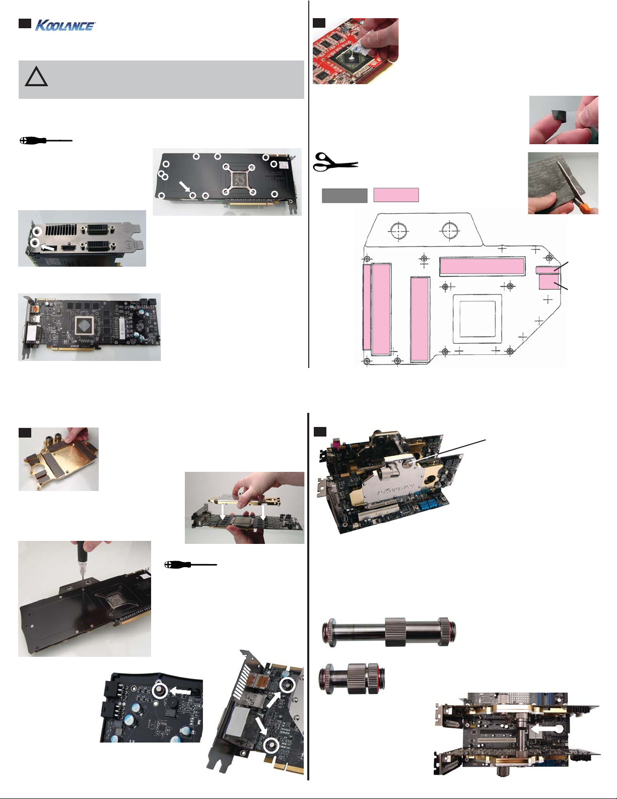
Thermal Paste Area
Thermal paste is only required on the main GPU. The
other areas will utilize the included heat transfer pads.
Spread thermal compound on the GPU thinly and evenly
using the included paste packet, or a piece of thick paper
(such as a business card). Thermal paste should not be
placed on the surrounding metal support frame or small
surface soldered components.
Most cards using the VID-series blocks are disassembled the same way, although
heat sink assemblies of any given model can vary.
The screws on the bottom side
should be removed first. There
should be about 15 of these on the
video card, plus 2 on the side of the
L-bracket.
Example: HD 5870 Disassembly Screws
(Side L-Bracket)
The heat sink and fan can now be
carefully removed. Original thermal
paste may present additional resistance
while removing the heat sink.
Unplug the heat sink fan wire. Remove
the original RAM thermal transfer
material, and wipe any residual thermal
material from the main GPU chipset.
Gray thermal pads have plastic fi lm on both sides that must
be removed before application. White/Pink thermal pads only
have plastic fi lm on one side (white) that must be removed.
Do this after cutting the proper shapes.
Please use the below diagram to determine
the proper sizes and type of thermal padding
needed.
Gray Pad
Pink Pad
70 x 7mm
75 x 16mm
70 x 16mm
70 x 16mm
20 x 6mm
18 x 13mm
3
Place heat transfer pads on each additional area cooled by
the Koolance liquid block, as determined by the previous
diagram.
Place the Koolance block over the video
card.
Using the Koolance-supplied screws,
tighten each screw on the reverse side
of the card. Utilize the original video
card screws for the rear GPU “cross
bracket”.
3 thumb nuts are
supplied to take the
place of empty screw
hole positions on
the top of the video
card.
4
Two G1/4 “caps” are included
with the VID coolers which can
be placed opposite the desired
nozzle locations.
Koolance VID coolers include redundant
G1/4 threading on both sides. This
means the input/output nozzles can be
placed on either side of the cooler.
Connecting VID Coolers in SLI or CrossFire
When connecting multiple VID coolers in series, Koolance offers an optional directconnect nozzle. This minimizes liquid routing while avoiding potential confl icts with
hardware in between the video cards.
Optional Three-Four Slot Dual Video Connector
Optional Two Slot Dual Video Connector
(Koolance CNT-VDA2)
(Koolance CNT-VDA34)
 Loading...