

Page 1
1
Koolance TMS-200 Installation Guide v1.02
Hardware Installation
The TMS interface card can be installed into a PCI or PCI-Express slot (with the included L-bracket), or mounted into a 5.25” bay
(using the included tray). All communication occurs via an external or internal USB port, even when installed into a motherboard
slot. The TMS hardware board is powered by a direct 12V power supply connection.
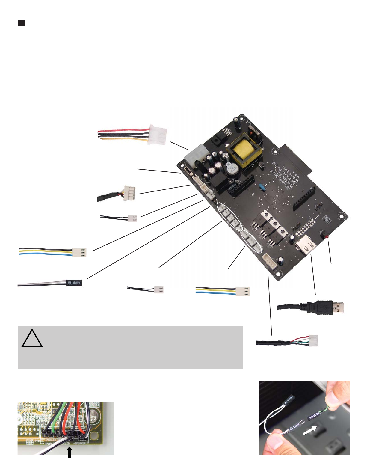
First, power-down the computer and connect all necessary wires to the TMS card. DO NOT CONNECT THE USB CABLE TO
THE COMPUTER. The internal or external USB cable will be connected to the computer after software installation. If needed,
extension wires for fans and the pump are included with the TMS board.
12V 4-pin Molex power
supply connection
Coolant fl ow meter LED switch (INS-FM16
only): off, on, or pulse according to fl ow rate
INS-FM16 Coolant fl ow meter
INS-FM17 Coolant fl ow meter
*Pump power connection:
**ATX Pass-through wire:
(sold separately)
(sold separately)
*CAUTION: Only Koolance pump models PMP-400 and PMP-450 are
compatible with TMS-200. The PMP-400 is found in Koolance PC4-1000,
!
RP-1000, and TNK-400 series products. Other models (such as the PC2,
PC3, Exos-1/LT, etc.) may damage the TMS board or computer power
supply if connected.
Temperature sensor
connections (#1 - 5)
Fan power connections
(#1 - 3)
Connection
Indicator
LED
External USB Connection
Internal USB Connection
**ATX pass-through wire: enables the hardware safety shutdown feature. Connect the
male ATX power lead from theTMS board to the computer chassis main power switch.
Connect the other female A TX power lead to the
motherboard’s power switch connection (often
marked “PWRSW”, “PWSW”, or “PWBT”).
This is the connection that would normally
receive the chassis power switch lead directly.
Page 2
2
Koolance TMS-200 Installation Guide v1.02
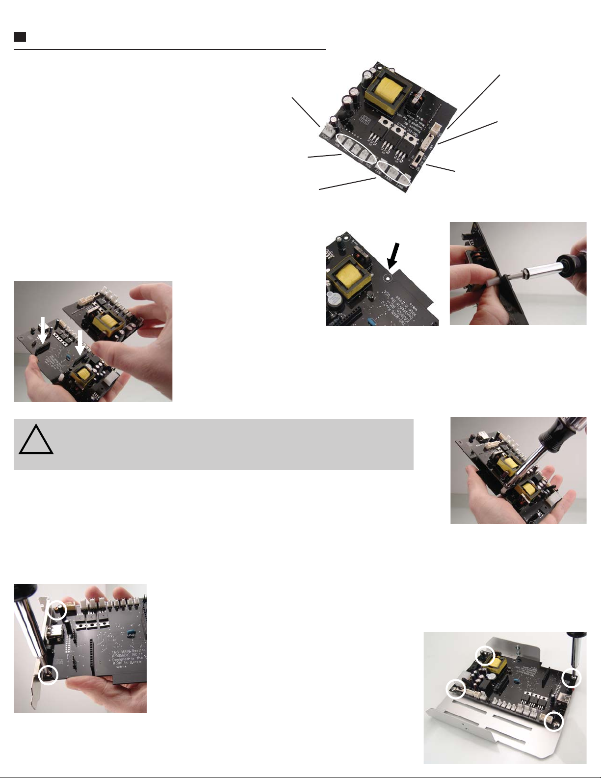
Expansion Board Installation
If you have purchased the optional
daughter expansion board for TMS-200,
please read this section. Otherwise, skip
to “Mounting” below.
Connect all necessary wires to the TMS
expansion board. If needed, extension
wires for fans and the pump are included
with the board.
The expansion board includes a standoff and two screws. Attach the
standoff to the top side of the TMS main board in the hole near the
dummy slot.
Make sure the connecting pins are aligned properly, and carefully insert the expansion board
into the TMS main board.
Pump #2 power (Same
pump models allowed as the
main board)
Temperature sensor
connections (#6 - 10)
Fan power connections
(#4 - 6)
INS-FM17 Coolant
fl ow meter
(sold separately)
INS-FM16 Coolant
fl ow meter
(sold separately)
Coolant fl ow meter LED
switch (INS-FM16 only): off,
on, or pulse according to
fl ow rate
The expansion board’s fan and temperature connections should face in the same direction as
the TMS main board connections. DO NOT INSTALL IT BACKWARDS!
CAUTION: The TMS expansion board must be aligned properly (top fan connectors
in the same direction as the main board fan connectors). Otherwise, permanent
!
hardware damage could result.
Finally, install the second screw to secure the expansion board to the standoff.
Mounting
Decide whether the TMS card will use the L-bracket (motherboard slot installation) or 5.25” tray (drive bay installation) and mount the
appropriate piece with the included screws. To help avoid physical damage, it is suggested to attach all necessary cables to the TMS
hardware before mounting the TMS board.
If the TMS-200 hardware board will be installed into an available motherboard slot, attach the included
I/O L-bracket with the smaller supplied screws.
NOTE: If using the optional expansion board with TMS-200,
the TMS hardware card will require two motherboard slots
instead of one.
If the hardware board will be installed into an available 5.25” bay, attach the included metal
tray with the larger supplied screws.
Page 3

3
Koolance TMS-200 Installation Guide v1.02
Software Installation
After connecting all wires to the TMS board and mounting it within the
computer case, power-up the computer. Launch the TMS executable
installation fi le for your OS (Windows Vista or XP). The USB plug should
still remain disconnected from the computer at this time.
If you accept the license terms, select “I Agree”.
Select the features you would like to install. The PL-2303 Drivers will be
necessary for the TMS software to communicate with the hardware card.
Use the appropriate TMS installation fi le for your operating system: XP or
Vista. (NOTE: Windows XP 64-bit users must install separate PL-2303
drivers. These will be placed under /x64/ in the TMS folder after installation,
and must be installed after TMS using Windows Device Manager.)
Select the desired hard drive installation location for TMS-200.
If PL-2303 drivers
were selected,
you will now be
prompted to install
these.
Page 4

4
Koolance TMS-200 Installation Guide v1.02
After software installation, connect one USB cable to the TMS board. Either loop the external cable back to an available external
port, or plug the internal cable from the TMS board to the motherboard’s internal USB header (if available).
CAUTION: If using the internal cable, be sure the motherboard’s USB pinout is compatible with the TMS cable.
Some motherboards may not take this particular type of wire layout. Also be sure NOT to connect the TMS cable to
!
a 1394 Firewire header, or hardware damage may result.
Windows should immediately begin loading drivers for the TMS device and Prolifi c PL-2303.
At this point, you may be prompted to reboot the computer.
(Reboot if requested.) After returning to Windows, launch the TMS installation via its desktop or startup menu
shortcut.
NOTE: If not prompted to run as Administrator , Windows Vista users may need to launch the TMS program by
right-clicking the shortcut and selecting “Run As Admin”. To avoid excessive messages, UAC (User Account
Control) could also be disabled using a program like Tweak-UAC.
The TMS main screen will display COM port communication. Initially,
it will scan for this connection. Once established, the COM port will be
displayed here. All available options in TMS will then be active.
If there are any alarms immediately sounding in TMS, the program will
need some confi guration (pump, fl ow meter , temperatures, etc.). Please
refer to the in-program TMS help menu for assistance.
If the COM Port Scan fails or stops, make sure there are no confl icts with the PL-2303 component under the device manager. If
so, try a different USB port. If there are no confl icts and TMS still cannot connect, follow this procedure:
1. Disconnect the USB cable from the TMS board.
2. Shutdown the computer using the Window’s shutdown option.
3. Bootup the computer and log back into Windows.
4. Restart the computer using the Window’s restart option.
5. After logging into Windows again, reconnect the USB cable to the TMS board.
This should fi x most connection issues. If not, there may be a hardware confl ict with the USB port that TMS is trying to use. The
COM Port Scan can be repeated in TMS under “Settings”->“Rescan”.
To learn how to operate the TMS software, please select “Help” in the TMS tray icon right-click
menu, or separately download the .CHM help fi le from Koolance’s website.
 Loading...