

Page 1

TM
Superior Liquid Cooling Systems
UNIVERSAL MANUAL
UNIVERSAL MANUAL
Protected by U.S. Patents 5,731,954; 6,234,240; 6,313,990
Other Technology Pending U.S. & World-Wide Patents
English v2.00
Page 2
This User Manual is updated regularly. Please be sure to check our support page for a
newer version of this guide:
www.koolance.com/support
GENERAL PRECAUTION
Please read this manual carefully before beginning the installation of your Koolance
system. This manual assumes the user has basic experience in building and configuring
computer systems. Information referring to traditional hardware assembly is intentionally
brief.
ABOUT SIGNS
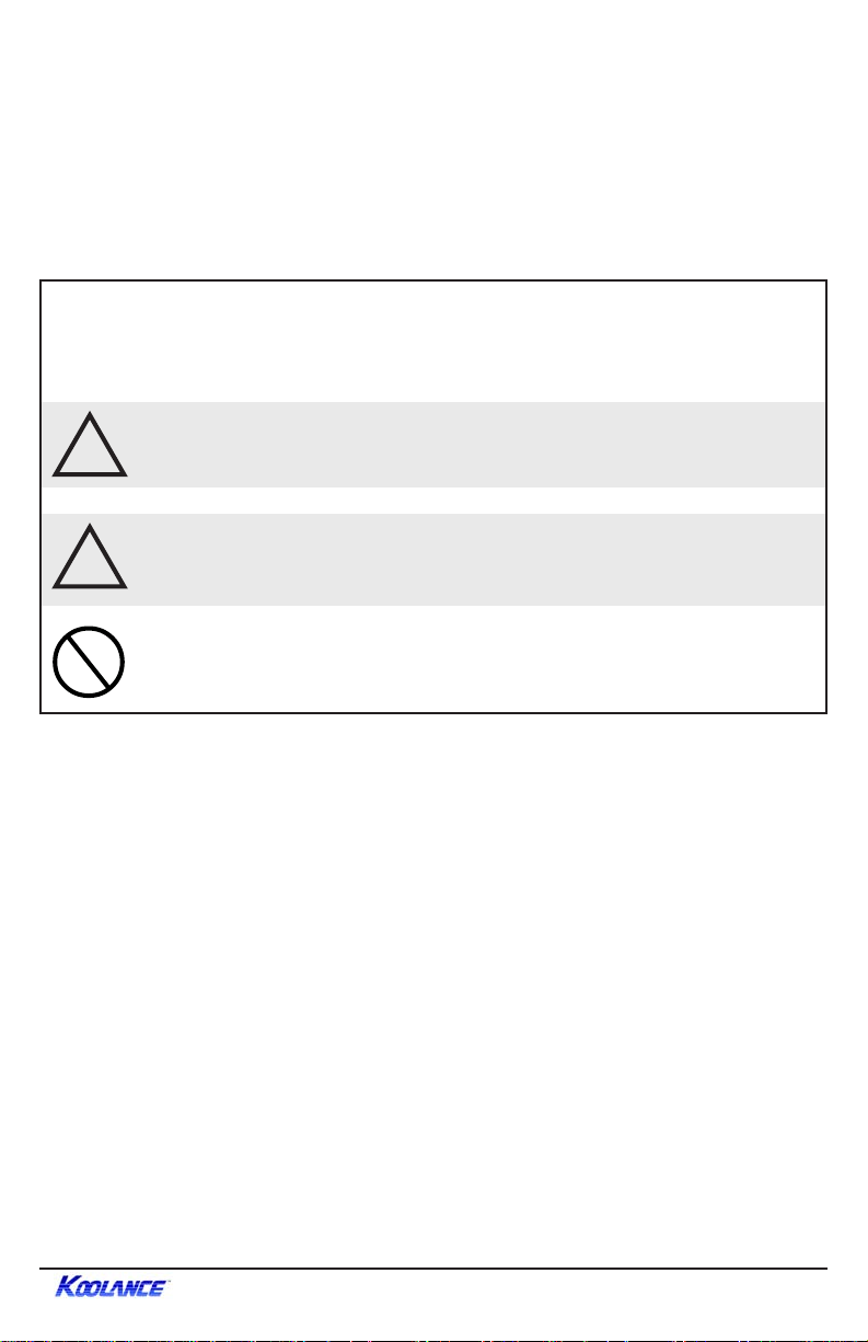
Throughout this document, critical information is highlighted in gray-colored boxes.
The following symbols are intended to prevent you from any situation which may
cause personal injury and/or damage to equipment:
WARNING: Indicates a potentially hazardous situation which, if not
!
avoided, could result in personal injury or be life-threatening.
CAUTION: Indicates a potentially hazardous situation which, if not
!
avoided, may result in damage to equipment.
PROHIBITED: Indicates a prohibited action.
PROHIBITED USE
This product is designed, developed and manufactured as contemplated for general
use, including without limitation: general office use, personal use and household use,
but is not designed, developed and manufactured as contemplated for use accompanying fatal risks or dangers that, unless extremely high safety is secured, could lead
directly to death, personal injury, severe physical damage or other loss, including
without limitation: nuclear power core control, airplane control, air traffic control, mass
transport operation control, life support, or weapon launching control. If these products
are used in such hazardous environments, Koolance Incorporated does not warrant
them.
TRADEMARKS
The Koolance name and logo, and the Exos name and logo are trademarks or
registered trademarks of Koolance, Inc. Other company and product names used in this
publication are for identification purposes only and may be trademarks or registered
trademarks of their respective companies.
COPYRIGHT
All rights reserved. Copyright (C) Koolance Incorporated 2003
iUser Manual
Page 3
WARNING: The Koolance liquid & coolant pack contain chemicals
!
!
!
which may be harmful or fatal if swallowed. KEEP THIS AND ALL
DANGEROUS CHEMICALS OUT OF THE REACH OF CHILDREN.
If ingestion has occurred, seek medical attention immediately . Give
two glasses of water. Do not induce vomiting. In the case of eye
contact, flush eyes immediately with water for 15 minutes. Remove
contact lenses. Call a physician if irritation persists. Some individuals
may have an allergic skin reaction with the solution, although generally mild. Avoid contact as much as possible, and wash exposed area
with soap and water for at least 15 minutes. If irritation persists, or if
contact has been prolonged, get medical help. For further information, please visit our website at: www.koolance.com
CAUTION: Koolance Incorporated can not be held responsible for
any damage to your system due to misconfiguration or incorrect
installation. If there is any point of installation that you do not understand, please contact our Technical Support Staf f at:
tech@koolance.com, or visit our website at: www.koolance.com
CAUTION: Liquid cooling systems are not yet universally supported
by hardware manufacturers. In some situations, adding liquid coolers
and other components to computer hardware might void the
manufacturer’s original warranty. Procedures which may impede on
hardware warranty will be indicated in the manual by gray-colored
Caution boxes. Installation of the device is ultimately done at the
user’s own risk. If you have any specific questions on warranty
coverage, please contact your component or computer manufacturer .
KOOLANCE CONT ACT INFORMATION
Koolance Inc. (USA)
Address: 1111 344th St. Ste. 202, Federal Way, WA, USA 98003
Telephone: +01-253-839-8999
Fax: +01-253-839-3307
Sales Email: sales@koolance.com
Tech Email: tech@koolance.com
Web: www.koolance.com
ii
Page 4

Table of Contents
Introduction............................................................................................1
PC2 System Diagram .................................................................4
IPC System Diagram ..................................................................5
ExosTM System Diagram ..............................................................6
LED Display Panel ......................................................................7
Reservoir & Pumps.....................................................................8
Heat Exchanger .......................................................................... 9
Power Control Board.................................................................10
Connecting PC2 & IPC Systems......................................................... 11
Power Control Board.................................................................12
Cooler Arrangement.................................................................. 13
Cutting Tube Lengths................................................................ 14
Connecting Tubes..................................................................... 15
Clamping .................................................................................. 16
Disconnecting ........................................................................... 17
Connecting Exos
TM
Systems................................................................ 18
Positioning the ExosTM...............................................................19
External Quick-Release Nozzles & Power Cable ......................20
Slot Interface Adapter ............................................................... 21
Cooler Arrangement.................................................................. 24
Cutting Tube Lengths................................................................ 25
Connecting Tubes..................................................................... 26
Clamping .................................................................................. 27
Disconnecting ........................................................................... 28
Installing Coolers.................................................................................29
Chipset Cooler on a Motherboard .............................................30
CPU Cooler...............................................................................32
Chipset Cooler on a Video Card................................................35
Hard Drive Cooler .....................................................................37
Filling & Maintenance..........................................................................40
Testing & Filling.........................................................................41
Draining & Maintenance............................................................ 44
Troubleshooting.....................................................................................45
Limited Warranty ...................................................................................48
iiiUser Manual
Page 5
Included Hardware
PC2 Series Systems:
- motherboard standoffs & insulating washers
- motherboard, slot card, 5.25” drive, and floppy screws
- hard drive mounting screws
- ATX power jumper wire
- refill funnel
- liquid coolant mixture
- extra PVC tubing
- drive mounting rails
- user manual
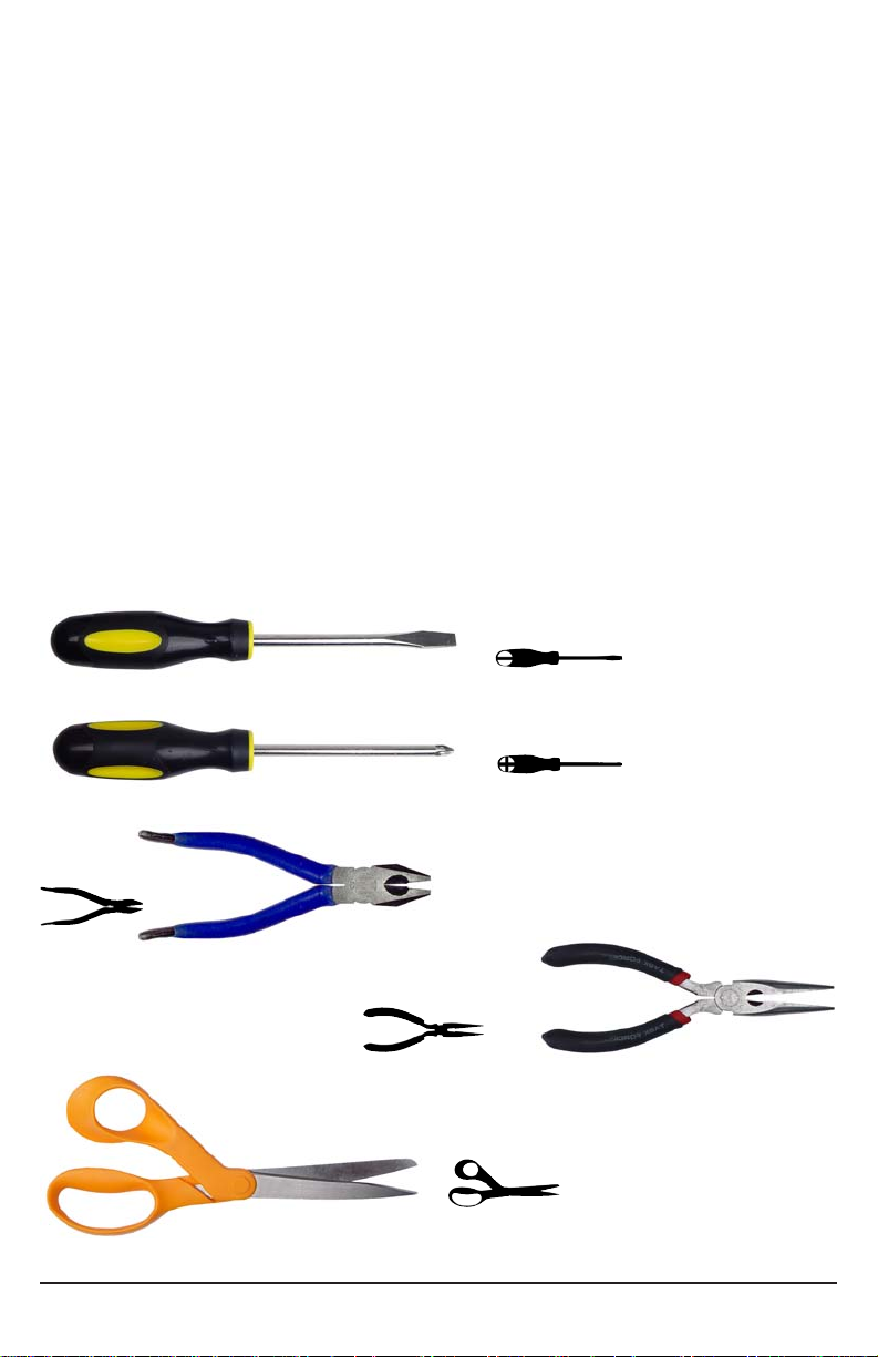
Required Tools
During installation, you may need the following tools:
flat-head screw driver
phillips-head screw driver
pliers
iv
needle-nose pliers
scissors
Page 6

Chapter1
Introduction
1User Manual
Page 7

Congratulations on your purchase of a Koolance system!
As the most sophisticated product of its kind, Koolance offers many unique
features found nowhere else in the realm of computer cooling. In addition, you can
expect to enjoy all of the advantages that water-cooling technology brings with it.
Advantages of W ater Cooling
Water transfers 30 times faster, and holds over 4 times more heat than air.
With this thermal conductivity and specific heat capacity, it’s easy to see why
liquid cooling is getting a lot of attention from hardware manufacturers.
Heat-producing devices in a typical computer are cooled by air. Generally , this
involves mounting a heat sink and fan to each component. For example, heat
generated from your CPU is transferred into a metal heat sink, where a fan blows
air across its wide surface area.
While altering a heat sink’s size and makeup can improve the effectiveness, it is
still limited because air absorbs and transfers heat very slowly . To help
compensate for this, the fan is often run at a higher speed. Many people have
therefore come to equate high performance with high noise. As systems continued
to be upgraded, the required heat sinks simply got larger and louder.
Liquid cooling greatly reduces the noise issue. A larger amount of heat is
withdrawn from the components more quickly , and less airflow is required to cool
them.
The heat exchanger is also located remotely from heat-producing devices, so
airflow can be controlled. This considerably reduces dust accumulation on sensitive
hardware and can result in a cleaner overall system.
Advantages of Koolance Systems
Koolance was the first company to offer fully-integrated, consumer-level PC liquid
cooling systems to the world-wide market. Our products are designed and built to
look and operate professionally. You will not need power tools or a tape
measure to install your Koolance system, and it should even be less difficult than
assembling your own computer.
Koolance offers liquid coolers for every major hardware device. Providing
enormous flexibility , you can customize your system to fit your specific needs—
cool dual processors in a server, multiple hard drives in a RAID configuration, or
add video cooling to a gaming rig.
2 Introduction
Page 8

The heart of a liquid cooling system is the pump. This device pushes liquid through
each cooler and into the heat exchanger. Koolance systems use dual pump s to
increase reliability and liquid pressure. If one pump should fail, the second can
help prevent potential damage caused by heat increase.
Every Koolance system includes built-in hardware safety features. Our
proprietary power control board constantly monitors liquid temperature, sounding
an alarm if it should get too high, and even turning-off your computer if you are not
there to do so.
But Koolance’s innovations extend beyond just cooling features. Our safe, patent-
pending CPU Retention Clip places even pressure across the CPU, protecting
the chip and simplifying installation. There’s even a ratcheting tension screw for
precise contact pressure.
Finally, Koolance systems allow coolers to be easily exchanged and upgraded
to address future hardware compatibility .
3User Manual
Page 9
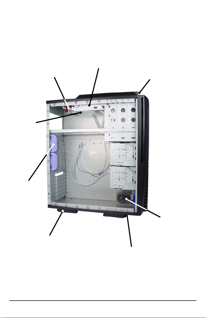
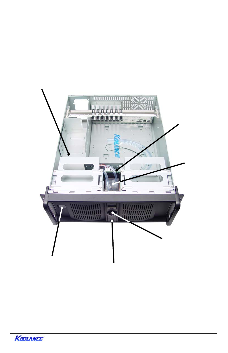
PC2 System Diagram
Heat Exchanger
Power Control Board
Air Duct
80mm Fan
Holders
LED Display Panel
Reservoir &
Pumps
Chassis Stabilizers
Liquid Refill T ap
4 Introduction
Page 10
IPC System Diagram
Heat Exchanger
Power Control
Board
Reservoir &
Pumps
LED Display Panel
Key Lock
Front USB Ports
5User Manual
Page 11
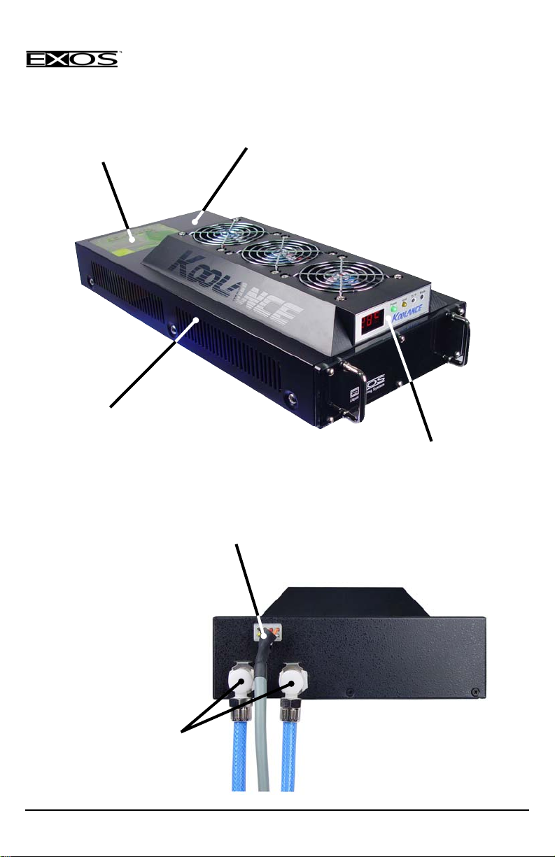
Exos System Diagram
Reservoir & Pumps
Heat Exchanger
Power Control Board
LED Display Panel
Power Connection
Liquid Quick-Release
V alves
6 Introduction
Page 12
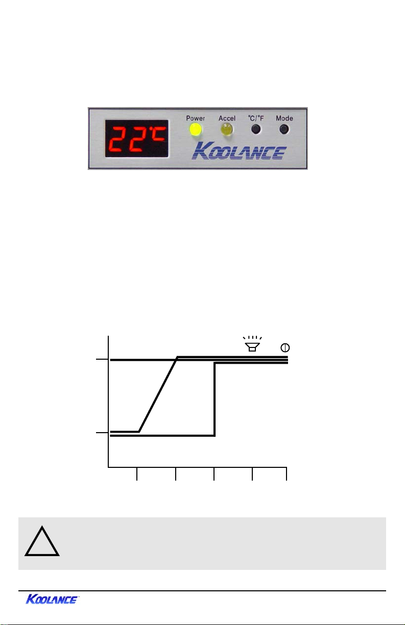
LED Display Panel
The front control panel is a convenient display which will allow you to monitor
liquid temperature, set the fan mode, and toggle temperature display settings (ºC
or ºF).
Mode 1 operates your system at 45% power until the temperature reaches 45ºC
(1 13ºF), then increases to 100% power.
Mode 2 operates your system at 45% power until the temperature reaches 35ºC
(95ºF), then increases gradually to 100% at 40ºC (104ºF).
Mode 3 runs the cooling system at 100% power. While this will provide the best
temperature range, it is not the most silent, and largely unnecessary in operating
your Koolance system.
The “Accelerated” light indicates that your system is running above 45% power .
100%
3
2
Audio Alarm
45%
Fan Power
35ºC 40ºC
95ºF 104ºF
CAUTION
!
automatically be shut-off to the entire computer . Unsaved files and
documents may be lost. Always make regular backups of your files.
: If the LED temperature reaches 53ºC (127ºF), power will
1
45ºC
113ºF
LED T emperature
50ºC
122ºF
Auto-Shutdown
53ºC
127ºF
7User Manual
Page 13
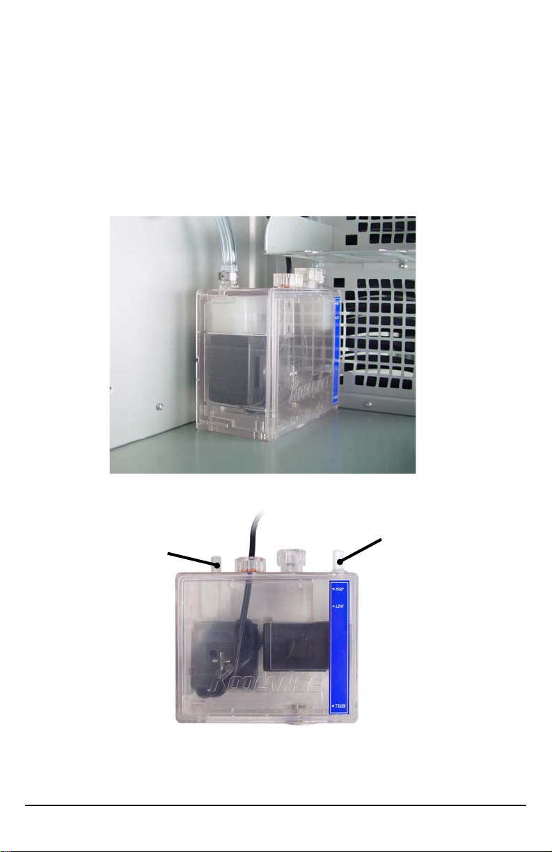
Reservoir & Pumps
The coolant tank includes many features which are distinctive to a Koolance
system. It is also translucent for easy liquid-level monitoring. Dual pumps carry a
flow rate of approximately 1030cc/min. Redundancy also provides higher system
reliability; if one pump should fail, the other will maintain an acceptable
temperature, or gradually bring the system to shut itself down (see LED Display
Panel).
Intake Nozzle
8 Introduction
Outlet Nozzle
Page 14
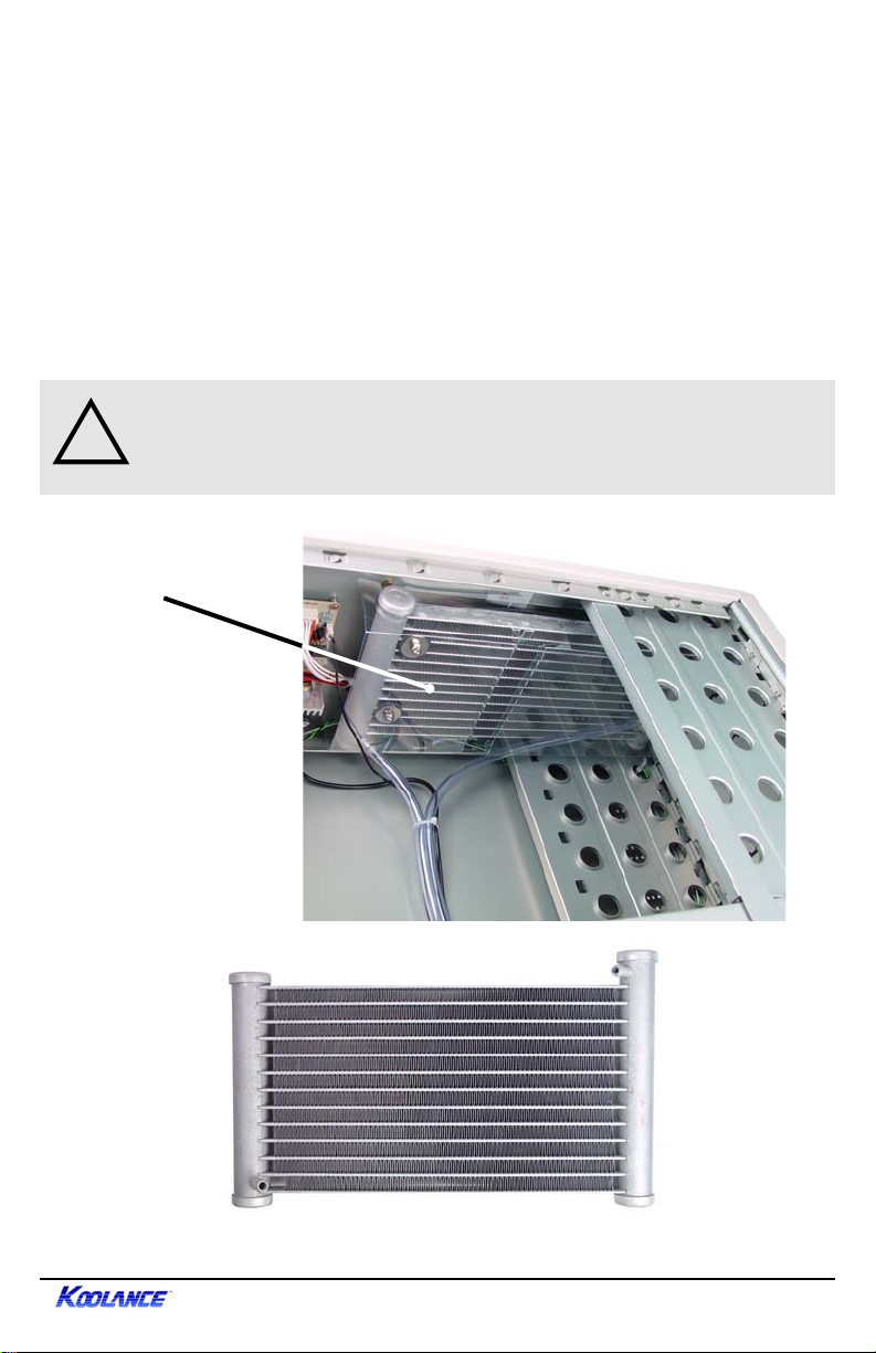
Heat Exchanger
The heat exchanger, or radiator , is located beneath the fan cooling module. This is
the primary cooling element, specifically designed for liquid cooling, and provides
high thermal dissipation in a relatively small area. Inside, an aluminum mesh
(Louver fin) is webbed between 13 horizontal liquid paths.
Below the heat exchanger is a plastic Air Duct. This guide helps shield hardware
from dust accumulation. It also directs airflow over the Power Control Board to
assist with cooling.
CAUTION: The plastic Air Duct beneath the Heat Exchanger in PC2
!
Systems assists with air separation and cooling. It should not be
removed.
Air Duct
9User Manual
Page 15
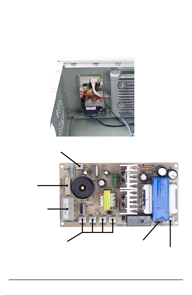
Power Control Board
Near the heat exchanger, the Power Control Board is responsible for a number of
tasks, including: powering the pumps, LED display , heat exchanger fans, and
operating the audio alarm and shutdown modes.
CPU T emperature Probe
LED Display
12V Power Supply
Connection
Heat Exchanger Fans
ATX Power Switch
Pass-Through Connections
Pumps
(NOTE: The Power Control Board connections and layout may vary depending on
the system model.)
10
Introduction
Page 16

(NOTE: Please skip to the next chapter if you have an Exos System)
Chapter2
Connecting PC2 &
IPC Systems
11User Manual
Page 17
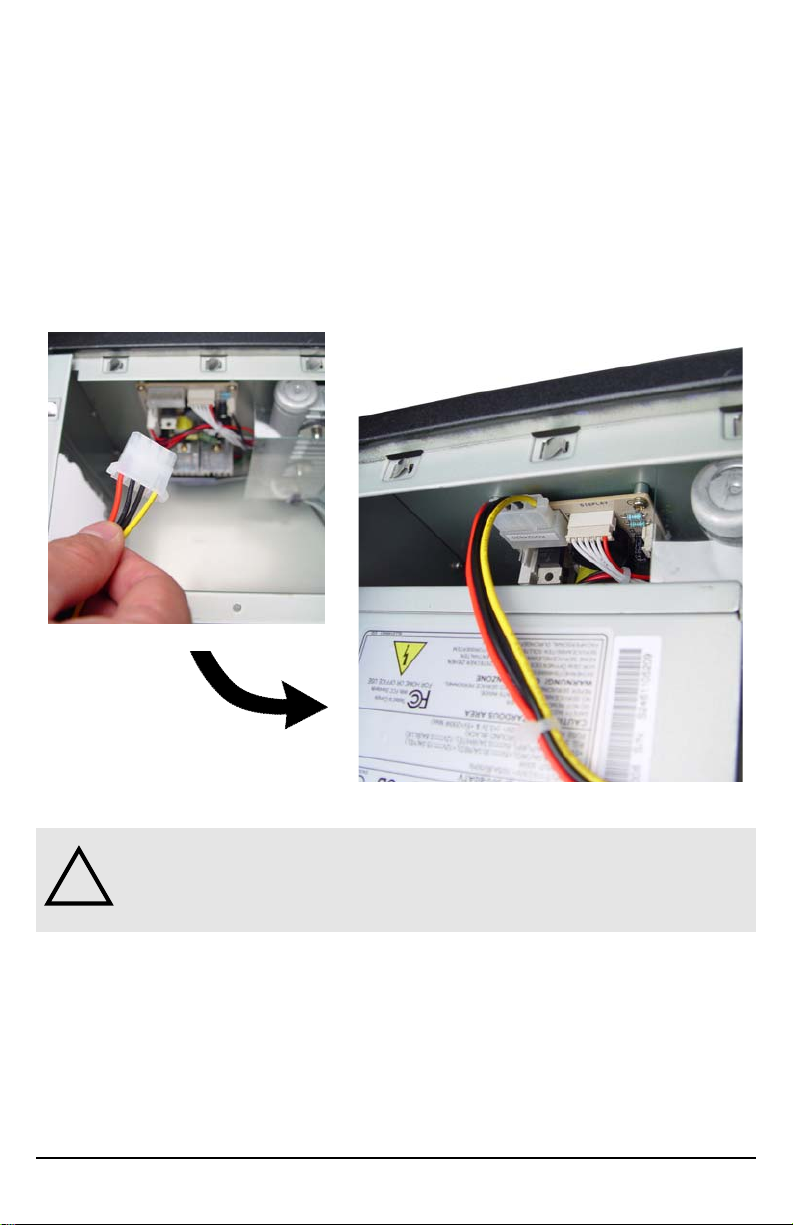
Power Control Board
Y ou may begin the installation of your Koolance system by mounting a power
supply in the chassis. The liquid cooling system requires approximately 8-10W
from any standard A TX power supply .
Connect a 12-volt 4-pin Molex plug from the power supply to the Power Control
Board. Without this important connection, the Koolance system will NOT operate.
12
CAUTION: The Power Control Board is vital to system operation. A
!
12V 4-pin plug from the power supply must remain connected to the
circuit at all times while the computer is in use.
Connecting PC2 & IPC Systems
Page 18

Cooler Arrangement
The components in your Koolance system are connected in series. Each system
contains a heat exchanger and reservoir , but you must choose which coolers you
wish to install in between, for example:
CPU Cooler, Motherboard Chip set Cooler, V ideo Chipset Cooler
CPU Cooler, 2nd CPU Cooler , Video Cooler , Hard Drive Cooler
Although it is possible to use up to eight (8) coolers in a Koolance system, a
maximum of six (6) is recommended due to a reduction in liquid pressure. Coolers
can also be added or removed later as required.
Typically, a cooler sequence will be:
1. Heat Exchanger
2. CPU Cooler
3. CPU Cooler (for dual-processor systems)
4. Motherboard Chipset Cooler
5. Video Card Chipset Cooler
6. Hard Drive Cooler
7. Reservoir (which connects back to the Heat Exchanger)
However, this order is optional and you may connect your coolers in an alternate
sequence if desired.
13User Manual
Page 19

Cutting Tube Lengths
Before securely clamping the coolers, you must cut appropriate lengths of tubing
to connect each device. It may be easier to temporarily lay your motherboard and
video card inside the case to better estimate the required amounts.
The system will come with two ends of tubing with which to attach your coolers.
These tubes are already connected and clamped to the Heat Exchanger and
Radiator.
Tube from Heat Exchanger
CPU Cooler Thermal Sensor
Tube to Reservoir
Additional tubing has been included with
your system should you require it, and
more can be purchased from your
Koolance dealer.
With one of the connected hoses,
roughly estimate the length you will
need to your first cooler (usually the
CPU cooler), and cut it.
Cut the second hose with enough length
to connect with the last cooler that will
be in your system.
Using the leftover tubing, cut shorter
pieces to link between each individual
cooler.
14 Connecting PC2 & IPC Systems
Page 20

Connecting Tubes
Each cooler kit contains clamps to secure
tubing to the cooler’s nozzles. Thread a
clamp onto each tube before connecting it to
the cooler nozzle.
Attach by squeezing the tube while pushing
firmly over the nozzle. The tubing should
completely cover the nozzle.
If you are finding it difficult to connect some
tubes (such as to the CPU cooler), try
temporarily stretching-out the tube end by
inserting need-nose pliers.
Continue connecting all of your
coolers in the system until there
are no longer any open tube ends.
Although it is most common for
tubing from the heat exchanger to
go directly to the CPU cooler,
liquid may circulate in either
direction through the coolers.
15User Manual
Page 21

Clamping
After every cooler is connected, you may tighten the clamps to secure them.
Clamping is done by positioning the reusable clamp just behind the cooler nozzle,
and slowly applying pressure on the adjustment lobe with pliers until it locks.
CAUTION: The clamp should be tightened behind the widened portion
!
16 Connecting PC2 & IPC Systems
of the cooler nozzle. Do not tighten a clamp over or on this nozzle
section, as damage may occur to the cooler.
Page 22

Disconnecting
Inevitably , a connection will need to be undone, either because you are adding
another cooler, or because something did not go properly during assembly . Be
sure there is no liquid within the system before unclamping a component (see
Draining for more information).
Clamps can be unlocked by inserting a small flat screw driver into the center of
the adjustment lobe and twisting. If done correctly , the clamp will snap open and
can be used again.
Unlocking
Cooler nozzles are designed to grip very tightly
to the tubing. If you find it difficult to remove a
tube after unlocking a clamp, try leveraging it
off with needle-nose pliers. (As a last resort, it
can also be carefully cut length-wise along the
cooler nozzle.)
Each time a metal clamp is removed, it will have distorted the tube beneath it.
This last portion (about 1cm, 7/16”) should be cut off to ensure a perfect fit with
the next connection.
17User Manual
Page 23

(NOTE: Please skip to the next chapter if you have a PC2 or IPC System)
Chapter3
TM
Connecting Exos
Systems
18 Connecting Exos Systems
Page 24

Positioning the Exos
TM
As an external unit, the Exos is designed to operate in various locations.
Based on testing, Koolance has found
the Exos to function adequately up to
10 meters (33 feet) away from most
computers, depending on the system
configuration and environment. (Excessive distance can lead to pump pressure
drop and undesirable temperatures,
however.)
The Exos must be operated upright. The
pumps and reservoir are less effective
when running sideways, and it is difficult
to maintain air filtration in this manner.
Rubber foot pads, or alternatively , self-adhesive velcro strips are included to attach
the Exos to your computer chassis. If you are frequently transporting your computer system, Koolance recommends the “Exos Attachment Belt” (purchased from
your Koolance dealer) to firmly strap the unit to your computer chassis.
Rubber Foot Pad
Exos Attachment Belt
Velcro Adhesive Strip
19User Manual
Page 25

External Quick-Release Nozzles & Power Cable
There are two segments of blue external tubing with your Exos system. You will
need to install a white quick-release nozzle on one end of each.
Thread a metal valve bolt over the end, and slide the tube over the narrow portion of
the nozzle. Tighten the metal bolt by firmly screwing it to the plastic nozzle.
Once completed, connect both quick-release
nozzles and the external power cable to the Exos.
If you are having difficulties inserting quick-release
nozzles into the rear connections, press the top
valve button to close the valve. The nozzle will not
fit into the Exos if the valve is open.
NOTE: Once filled, it is normal for the quickrelease nozzles to leak a small amount of liquid
upon disconnection.
20 Connecting Exos Systems
Page 26

Slot Interface Adapter
The Slot Interface Adapter allows the Exos to connect with any computer through
an available card slot. It is responsible for both input and output tubes, along with
the external power cable connection. This prevents the computer chassis from
requiring any modifications.
Install the Interface Adapter from the inside
of the case, guiding the tension springs out
the back of the slot. The Interface Adapter
may be installed into any available rear card
slot in your computer.
Screw the Interface Adapter in place as you
would a normal device.
From the rear of the case, carefully feed both
ends of the liquid tubing through the tension
springs and into the chassis.
Plug the remaining end of the Exos
external power cable into the Slot Interface
Adapter.
21User Manual
Page 27

CPU Temperature
Probe
Case ATX Power Switch
Motherboard Power Switch
Optional Fan
Connections
Exos External
Connection
There are 4 main connections to the Slot Interface card which must be made. The
Exos may appear to operate without some of these connections, but the hardware
safety features will be deactivated.
Power Supply 4pin 12V
The Exos cooling system requires
approximately 8-10W from any
standard A TX power supply . Since
it is adapted internally , the Exos
does not need a dedicated
external AC power cable.
Connect a 12-volt 4-pin Molex
plug from the power supply to the
Slot Interface Adapter . Without
this important connection, the
Exos system will NOT operate.
CAUTION: The Slot Interface Card is vital to system operation. A 12V
!
22 Connecting Exos Systems
4-pin plug from the power supply must remain connected to the circuit
at all times while the computer is in use.
Page 28

The black CPU temperature probe is the reading displayed by the front LED panel.
Y ou will position this thermal probe later during the installation of your CPU cooler .
There are 2 power switch connections on the Slot Interface Card. Instead of
connecting the chassis power switch to your motherboard, it will meet with a wire
to the Slot Interface Adapter .
Unplug the chassis A TX power switch lead from
the motherboard. The power switch is typically
labeled “PWRSW”, “PWSW”, or “PWBT”.
Connect this lead to the pronged male
connection from the Exos Slot Interface
Adapter.
The second lead from the Slot Interface
will connect to your motherboard where
the power switch was originally
located.
The new A TX power switch connection
originates from the Slot Interface Adapter .
All other wire leads to your motherboard
should remain connected.
23User Manual
Page 29

Cooler Arrangement
The components in your Koolance system are connected in series. Each system
contains a heat exchanger and reservoir , but you must choose which coolers you
wish to install in between, for example:
CPU Cooler, Motherboard Chip set Cooler, V ideo Chipset Cooler
CPU Cooler, 2nd CPU Cooler , Video Cooler , Hard Drive Cooler
Although it is possible to use up to eight (8) coolers in a Koolance system, a
maximum of six (6) is recommended due to a reduction in liquid pressure. Coolers
can also be added or removed later as required.
Typically, a cooler sequence will be:
1. Exos
2. CPU Cooler
3. CPU Cooler (for dual-processor systems)
4. Motherboard Chipset Cooler
5. Video Card Chipset Cooler
6. Hard Drive Cooler
7. Exos (which connects the reservoir and heat exchanger)
However, this order is optional and you may connect your coolers in an alternate
sequence if desired.
24
Connecting Exos Systems
Page 30

Cutting Tube Lengths
Before securely clamping the coolers, you must cut appropriate lengths of tubing
with scissors to connect each device. If you are building a new computer system,
it may be easier to temporarily lay the motherboard and CPU inside the case to
better estimate the required amounts.
The Exos external (blue) tubing connects
to the first and last coolers in your
system. St andard (clear) tubing is used
in between each individual cooler.
Additional tubing has been included with
your system should you require it, and
more can be purchased from your
Koolance dealer.
With one of the connected
hoses, roughly estimate the
length you will need to your first
cooler (usually the CPU cooler),
and cut it.
Although it is most common for
tubing from the heat exchanger to
go directly to the CPU cooler, liquid
may circulate in either direction
through the coolers.
Cut the second hose with enough
length to connect with the last
cooler that will be in your
system.
Using the standard clear tubing,
cut shorter pieces to link
between each individual cooler.
Heat Exchanger Output
Reservoir Input
25User Manual
Page 31

Connecting Tubes
Each cooler kit contains clamps to secure
tubing to the cooler’s nozzles. Thread a
clamp onto each tube before connecting it to
the cooler nozzle.
Attach by squeezing the tube while pushing
firmly over the nozzle. The tubing should
completely cover the nozzle.
If you are finding it difficult to connect some
tubes (such as to the CPU cooler), try
temporarily stretching-out the tube end by
inserting need-nose pliers.
26
Continue connecting all of your
coolers in the system until there
are no longer any open tube ends.
Connecting Exos Systems
Page 32

Clamping
After every cooler is connected, you may tighten the clamps to secure them.
Clamping is done by positioning the reusable clamp just behind the cooler nozzle,
and slowly applying pressure on the adjustment lobe with pliers until it locks.
CAUTION: The clamp should be tightened behind the widened portion
!
of the cooler nozzle. Do not tighten a clamp over or on this nozzle
section, as damage may occur to the cooler.
27User Manual
Page 33

Disconnecting
Inevitably , a connection will need to be undone, either because you are adding
another cooler, or because something did not go properly during assembly . Be
sure there is no liquid within the system before unclamping a component (see
Draining for more information).
Clamps can be unlocked by inserting a small flat screw driver into the center of
the adjustment lobe and twisting. If done correctly , the clamp will snap open and
can be used again.
Unlocking
Cooler nozzles are designed to grip very tightly
to the tubing. If you find it difficult to remove a
tube after unlocking a clamp, try leveraging it
off with needle-nose pliers. (As a last resort, it
can also be carefully cut length-wise along the
cooler nozzle.)
Each time a metal clamp is removed, it will have distorted the tube beneath it.
This last portion (about 1cm, 7/16”) should be cut off to ensure a perfect fit with
the next connection.
28 Connecting Exos Systems
Page 34

Chapter4
Installing Coolers
29User Manual
Page 35

Chipset Cooler on a Motherboard
The chipset cooler is used for both motherboard northbridge and video card
chipsets. If installed, the motherboard must be partially removed from the chassis
in order to install the chipset cooler . (The mounting screws are inserted from the
back side of the board.)
CAUTION: Removal of the original heatsink my void your
!
manufacturer’s hardware warranty. Please consult the manufacturer if
unsure, and keep all original parts in case of a return/RMA. Koolance
does not recommend using a liquid cooler on video cards or
motherboards that lack standard mounting holes, or have heat sinks
that are attached with only an adhesive (rather than screws or bolts).
Beneath the motherboard, the plastic tabs
must be squeezed together with needlenose pliers in order to free the original heat
sink. (Some tabs have locking center pins
which must first be removed from the top.)
30
Once loosened, remove
the original heat sink.
Apply a thin layer of
thermal interface
compound onto the
chipset if necessary .
Installing Coolers
Page 36

Remove the protective tape from the bottom
of the chipset cooler .
Through the original motherboard mounting holes,
insert both plastic mounting screws from the back
of the board.
T o help keep them secure, place rubber washers
over the plastic screws from above the board.
Use the metal attachment nuts to fasten the
mounting bracket chipset to the motherboard.
Hand-tighten all motherboard components.
31User Manual
Page 37

CPU Cooler
The most prominent liquid cooler is also the easiest
to install.
Apply thermal interface compound directly to the
CPU die. Do not add more than is necessary to cover
it with a very thin layer.
Remove the protective film from the bottom of
the CPU cooler.
Insert the temperature sensor into either
bottom groove on the CPU cooler.
Apply metal tape to keep the temperature
probe in place. Do not stick metal tape to the
the raised (polished) portion of the CPU cold
plate.
Y ou can use a zip-tie to further secure the
temperature probe to the CPU tubing.
CAUTION: Be sure to attach the Koolance temperature probe to the
!
32
CPU cooler during installation. The safety features of your system
may not function properly without the correct placement of this probe.
Installing Coolers
Page 38

Assemble the CPU mounting bracket using the appropriate clips. The longer pair
are for Intel P-4 processors; the shorter are for AMD Athlon/XP and Intel P-III
processors.
Clips for P-4 socket 478
Fit the cooler and mounting brackets onto
the CPU socket. The bracket clips slide
inward and outward to hook to the socket.
Check that the bracket clips are aligned
before installing the tension screw.
Insert and slowly twist the tension screw
until it can no longer be tightened. Overtightening is prevented by a ratcheting
action.
Clips for AMD socket 472
& P-III socket 370
There are 3 center receptacles on the CPU cooler . The tension screw must use
the receptacle that best-aligns it over the processor die’s center .
33User Manual
Page 39

CAUTION: Installing the tension screw into the wrong cooler
!
receptacle can cause insufficient cooler contact, and may result in
hardware damage.
AMD
(left)
Intel P4
AMD
(right)
Many processor dies are not equidistant from one edge of the socket to the other .
For most AMD processors, the left or right recept acles will be used, depending on
which direction the CPU socket faces. For Pentium-4 processors, use the center
hole.
Socket alignment for
right AMD processors
Socket alignment for
left AMD processors
Socket alignment for P-4
processors
34
Installing Coolers
Page 40

Chipset Cooler on a Video Card
The chipset cooler is used for both motherboard northbridge and video card
chipsets. If installed, the video card should be removed from the chassis in order
to install the chipset cooler . (The mounting screws are inserted from the back side
of the board.)
CAUTION: Removal of the original heatsink my void your
!
manufacturer’s hardware warranty. Please consult the manufacturer if
unsure, and keep all original parts in case of a return/RMA. Koolance
does not recommend using a liquid cooler on video cards or
motherboards that lack standard mounting holes, or have heat sinks
that are attached with only an adhesive (rather than screws or bolts).
Beneath the motherboard, the plastic tabs
must be squeezed together with needle-nose
pliers in order to free the original heat sink.
(Some tabs have locking center pins which
must first be removed from the top.)
Once loosened, remove the original heat
sink. Apply a thin layer of thermal
interface compound onto the chipset if
necessary.
35User Manual
Page 41

Remove the protective
tape from the bottom
of the chipset cooler .
Through the original
mounting holes, insert
both plastic mounting
screws from the back
of the video card.
T o help keep them secure, place rubber washers on
the plastic screws above the board.
If required, use the bracket extension tabs to reach
the chipset’s mounting holes. The extensions are
highly-adjustable for proper alignment.
36
Use the metal attachment nuts to fasten the
mounting bracket to the video card chipset.
Hand-tighten all video card components.
Installing Coolers
Page 42

Hard Drive Cooler
Once mixed, the dual-pack of thermal encapsulate
material will serve as the heat transfer pad between
your drive and the cooling plate. It is not electrically
conductive, and the material can be peeled-off after it
has dried (after 60 hours). Hard drives may be used
while the encapsulate is drying.
CAUTION: Because the encapsulate can only be used once,
!
!
Koolance recommends formatting and installing software onto a new
hard drive to verify a drive defect before installing the liquid cooler.
Additional thermal packs are available with “second hard drive kits”
from your Koolance reseller.
CAUTION: The original hard drive manufacturer may not honor the
warranty if residue from the encapsulate material remains after
removal. If you have any questions on warranty coverage, please
contact your drive’s manufacturer .
Fold the dual-pack of encapsulate in half, and cut
a corner across, so that both compounds can be
squeezed-out together.
Compress the entire pack over a sheet of paper until
the contents are empty .
Using a spoon or mixing
utensil, stir the
encapsulate like paint
until it is one complete
solid color.
37User Manual
Page 43

CAUTION: Some hard drives have open spindle motors or other
connections which encapsulate may interfere with. Tape should be
!
placed over these areas before applying the thermal encapsulate.
Using the mixing utensil, apply the encapsulate to the largest heat-producing components:
the spindle motor and primary circuit chips
on the bottom side of the drive.
Use the included screws to mount the
cooler over the encapsulate on the bottom side of the hard drive. The drive may
be mounted into your case via the cooler
or the drive.
38 Installing Coolers
Page 44

If you have a Koolance chassis, the hard drive
cooler can be used with 2 hard drives. The
second hard drive will require a “Second Hard
Drive Kit” (purchased from your local
Koolance dealer).
Install the Second Hard Drive Kit as you
would a regular Cooler. Thermal encapsulate is applied to the drive, and the thin
metal “Containment Plate” is screwed over
it to the bottom of the hard drive.
First Hard Drive
Thermal Encapsulate
Liquid
Cooler
Mounting Screws
Rear view of Hard Drive Cooler Assembly for
first hard drive (above), and second hard drive (below)
The second drive is mounted upside-down
to the cooler, held in place via it s own sidemounting screws.
Mounting Screws
Containment Plate
Thermal Encapsulate
Second Hard Drive
39User Manual
Page 45

Chapter5
Filling & Maintenance
40 Filling & Maintenance
Page 46

Testing & Filling
Your Koolance system is designed to automatically filter air from the liquid. Before
filling, the cooling system should be “jump-started” to assist in the circulation process.
Make sure the AC power cord is attached to the power supply . If the power supply has
a rear switch, it must be in the ON (-) position. Using the A TX Jumper Wire, insert the
metal prongs into pin numbers 4 and 6 on the 20-pin motherboard A TX power supply
connector (green and a black ground wire-- See diagram).
46
CAUTION: Jumping the incorrect A TX power supply pins can cause
!
permanent damage to the power supply .
Y ou should now hear the pumps running in an empty
reservoir.
The refill tap is located beneath the case. Turn the
system upside-down and remove the large slot-headed
screw.
With the system upside-down, insert the refill funnel.
41User Manual
Page 47

WARNING: The liquid coolant is electrically conductive. Use caution
!
Cut a small corner in the coolant pack, and slowly
fill the reservoir. Y ou will probably not need the
entire amount of liquid.
when filling the system, and keep all liquids away from computer
hardware and power cables. In case of emergency during installation,
immediately unplug the computer’s rear power cable. Dry the system
thoroughly before proceeding.
The reservoir should be filled up to the “Refill”
indicator arrow.
Replace the refill tap screw , and stand the system back
upright. When filtration has ended (usually after about
1-5 minutes), the liquid noise will stop.
42 Filling & Maintenance
Page 48

CAUTION: Positioning of Exos systems during liquid filling is impor-
!
Because of gravity , the Exos must be placed above all internal cooling
components while being filled. Otherwise, coolant will exit the refill tap once the
reservoir is full.
tant. The Exos must be higher than all internal cooling components,
or coolant will exit the refill tap upon filling.
43User Manual
Page 49

Draining & Maintenance
The liquid coolant in your system should be emptied for any of the below reasons:
1. T o Keep it Clean - Koolance recommends replacing the liquid coolant once
every 12 months. The coolant should also be replaced if it becomes contaminated
or significantly changes color.
2. Upgrading Coolers - Whether you are adding or removing liquid coolers,
upgrades can be performed more easily with a dry system.
3. Shipping - Koolance recommends draining the liquid coolant if the system is to
be shipped or transported in a method other than by hand.
(NOTE: In situations #2 and #3 above, the liquid coolant can later be reused if
cleanly bottled.) Additional coolant may be purchased from your local Koolance
dealer.
CAUTION: Because of the risk of leakage, Koolance recommends
!
removing computer hardware before draining your system.
Before draining the system, it should be placed
upright on a table with the bottom refill tap overhanging. Place a 1-liter container below the
opening to capture liquid. Unscrew the refill tap to
begin draining the system.
Most of the liquid will not fall out until a cooler
nozzle has been unattached. Remove the
tubing from a single cooler nozzle connection
within the chassis and hold the end up.
44
Filling & Maintenance
Page 50

Troubleshooting
We hope your Koolance system will provide you with years of reliable cooling
performance. T o help avoid unnecessary RMA issues, we have prepared this list of
possible operational problems, and their most common solutions.
1. How do I tell if the pumps are working?...
After inital air-filtering, the pumps may not create enough noise to tell if
they’re working properly . During normal operation, some air bubbles may
even remain attached to the insides of the hoses and will not appear to
move when the tubing is “flicked”.
The easiest way to test pump operations is to simply monitor liquid inside
the reservoir. If the pump s are operating, liquid flow will be visible.
2. My temperatures seem too high...
Since BIOS temperatures can not always be relied upon to give accurate
readings for liquid cooling systems, “overheating” problems are difficult to
diagnose. If the system exhibits signs of high temperature (reboots, shutdowns, etc.), there may be a problem with your system. These same
symptoms can also be attributed to a faulty power supply , and other
internal hardware.
Verify that the liquid coolers are making suf ficient contact with each
component. Make sure the CPU tension screw is placed in the correct
cooler receptacle (see CPU Cooler).
If the thermal interface material has become over-used, or if the protective
film on the CPU has not been removed, the CPU can exhibit higher
temperatures than normal.
Also check that there are no blocks, twists, or crimps in the tubing
system. If a nozzle has been clamped inappropriately , it should be redone.
3. The LED Display Panel does not light up...
A defective display circuit is extremely rare. Usually, this is due to a
misaligned or disconnected plug on the Power Control Board (or Exos Slot
Interface Adapter). V erify that all appropriate plugins are attached, p articularly the 12V 4-pin power supply connection.
45User Manual
Page 51

4. Af ter the system has been on for awhile, the temperature alarm sounds...
Make sure that the LED temperature reads at least 50ºC (122ºF) or higher
while the alarm is sounding; if not, the audio alarm may in fact be your
motherboard’s BIOS alarm. If the system is not exhibiting signs of overheating (see #2 in Troubleshooting), this temperature monitor may need to
be disabled to ignore false readings by BIOS. The Koolance LED Display
will flash “FL T” (fault) whenever the cooling system alarm sounds.
If the alarm sounds within a few seconds after a cold boot-up, or the LED
temperature does not read at least 50ºC (122ºF) while the alarm is on, the
control board/pumps may be malfunctioning. Please visit our support web
page for more information.
Verify that the pumps are operating (see Troubleshooting #1), and that
liquid flow is present in the reservoir. Note that if the reservoir was overfilled during system assembly , this procedure is not possible.
5. My system has boot-up problems, or does not turn on...
The majority of these problems are not related to the Koolance case, but
hardware or configuration issues. In a new system, a problem with the
RAM, motherboard, power supply , video card, processor, or monitor can
cause the system to appear not to boot-up properly .
46
If the top Heat Exchanger fans do not spin, or if the front LED Display
Panel does not light-up, check to see if your motherboard has a power
indicator LED on the board. This is usually a green light next to the A TX
power connector on newer motherboards. If this is lit, power is getting to
the board.
The Power Control Board (or Exos Slot Interface Adapter) should be
checked to make sure all connections are plugged-in, especially the 12V
4-pin power supply connection. Also be sure if your power supply has a
rear power switch, that it is in the ON (“-”) position, and switched to the
appropriate regional current (1 15V AC or 220VAC).
Another possibility is that the motherboard is shorting-out electrically on
the chassis. Remove the motherboard, and verify that the stand-offs are
properly installed. Lastly , check that the IO shield (the thin aluminum rear
motherboard A TX port plate) is not bent backwards around the
motherboard, possibly shorting a component.
If further problems persist, you are likely having a separate hardware issue.
Page 52

6. My system appears to be leaking fluid...
Since users are allowed to configure their own coolers and clamps, it is
possible a connection was not properly sealed (however unlikely). If you
can see liquid somewhere on the tubing, or at the bottom of the chassis,
computer components may need to be removed for a system test (see
Flow T esting).
If liquid should get onto another computer component, shut down the
system, and remove the component. In most cases, the hardware will be
fine after allowing it to dry . However , the system should not be operated
until you have discovered where the leak is coming from and can repair the
problem. Should the leak be situated somewhere in which it can not be
easily repaired, please contact our Technical Department for further
diagnostic information.
7. My computer’s BIOS gives me errors that there are no cooling fans attached...
Some motherboards will not boot, or may generate an error or alarm if no
cooling fans are attached to the CPU or motherboard chipset power
connectors. There is sometimes an option to disable these fan connections in BIOS, but you may have to boot-up with a fan attached initially to
disable this setting. If the system is not booting due to this problem, clear
the CMOS and try configuring BIOS again.
8. The LED Display Panel flashes “00 / FL T (Fault)”...
The CPU T emperature Probe is uplugged from the Power Control Board (or
Exos Slot Interface Adapter) or has become damaged. Please check this
connection, or contact our Technical Department if the probe is defective.
47User Manual
Page 53

Limited Warranty
Koolance Incorporated (“Koolance”) warrants each new Koolance liquid-cooled
system (“the system”), against defects in materials or workmanship for a period of
one year from the date of purchase, and agrees to repair or replace any defective
Koolance system without charge. Shipping costs are non-refundable.
This warranty is non-transferable. All warranty claims must be accompanied by the
original proof of purchase.
THIS WARRANTY DOES NOT COVER DAMAGE RESULTING FROM ACCIDENT , MISUSE
OR ABUSE, LACK OF REASONABLE CARE, SHIPPING DAMAGE, MODIFICA TIONS, THE
AFFIXING OF ANY A TT ACHMENT NOT PROVIDED WITH THE PRODUCT , LOSS OF
PAR TS, OR OPERA TING COMPONENTS A T SPEEDS OR FUNCTIONS OTHER THAN
THOSE SPECIFIED BY THEIR MANUF ACTURERS.
Use of unauthorized replacement parts or liquid additives will void this warranty.
Koolance Incorporated will not pay for warranty service performed by a non-authorized
repair or diagnostic service and will not reimburse the consumer for damage resulting
from warranty service performed by a non-authorized repair service. No responsibility is
assumed for any special incidental or consequential damages due to a defective
Koolance product.
In order to obtain warranty service, contact our RMA department for information. The
product must be shipped postage prepaid to an authorized Koolance service location. It
is suggested that, for your protection, you return shipments of product by insured mail,
insurance prepaid. Damage occurring during shipment is not covered by this warranty.
Shipping costs are non-refundable. No other warranty, written or oral, is authorized by
Koolance Incorporated.
Disclaimer
IN NO EVENT SHALL KOOLANCE INCORPORA TED OR ITS EMPLOYEES, AGENTS,
SUPPLIERS, MANUFACTURERS, OR CONTRACTORS BE LIABLE FOR ANY DAMAGES
OF ANY KIND OR CHARACTER, INCLUDING WITHOUT LIMIT A TION ANY
COMPENSA TORY, INCIDENTAL, DIRECT, INDIRECT, SPECIAL, PUNITIVE, OR
CONSEQUENTIAL DAMAGES, LOSS OF USE, LOSS OF DA T A, LOSS OF INCOME OR
PROFIT , LOSS OF OR DAMAGE T O PERSONS OR PROPERTY, CLAIMS OF THIRD
PAR TIES, OR OTHER LOSSES OF ANY KIND OR CHARACTER, AND WHETHER OR
NOT THE POSSIBILITY OF SUCH LOSS OR DAMAGE HAS BEEN NOTIFIED TO
KOOLANCE INCORPORA TED.
48
Page 54

www.koolance.com
ISO
9001
Printed in Korea
 Loading...