

Page 1
Page 1
RAM-35 Installation Guide v 1.0
www.koolance.com
CAUTION - Koolance’s patented Hydra-Pak™ Coolers are puncture resistant, but not puncture proof. To avoid rupturing
!
your Hydra-Pak™ Cooler, it is recommended to carefully cover any excessively sharp areas (for example, solder points or
corners) on your hardware with small pieces of foam or electrical tape.
3rd-party liquid cooling products are not generally supported by hardware manufacturers. Installing a Koolance liquid cooling
product is ultimately done at the user’s own risk.
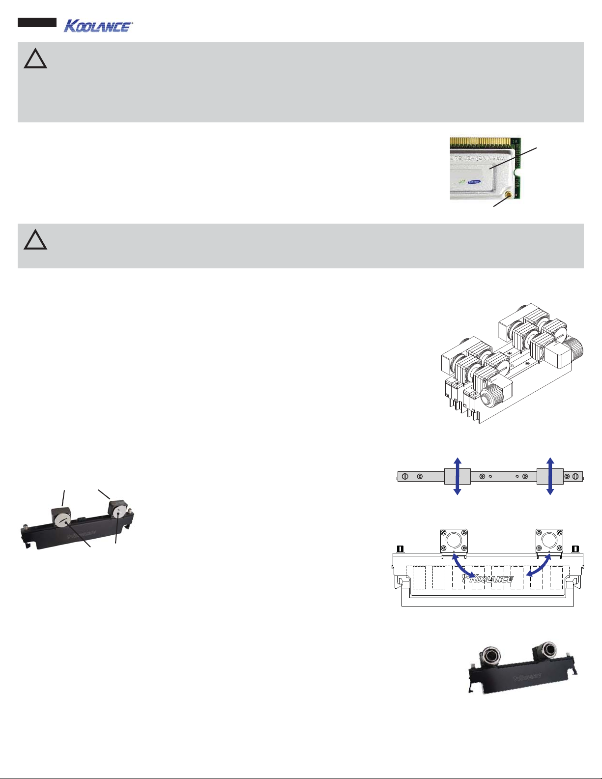
Y our memory stick may include a metal heat spreader or heat sink. In order to fi t within the RAM-
Heat
Spreader
35, the original heat spreader(s) must fi rst be removed. Most heat spreaders are attached with
either metal brackets, screws, or thermal tape.
Memory sticks which have heat spreaders that are soldered, riveted, or glued are not recommended
for use with the RAM-35 due to the increased possibility for damage upon disassembly.
Rivet
CAUTION - Attempting to remove a memory heat spreader can damage the memory. Make sure the heat spreader is not
!
soldered, riveted, or glued onto the memory stick. If attached with a tape adhesive, be very careful when removing the heat
spreader so as not to damage the memory stick.
Each RAM-35 will cool one DIMM memory stick in one slot. For multiple DIMM cooling, Koolance provides special connection
types for the RAM-35, discussed later.
Summary of Installing the RAM-35
On a typical motherboard, there is very little space between memory slots for a water block, let
alone one that channels liquid directly along both sides of each memory stick. The Koolance
RAM-35 does just that, but because of motherboard space limitations, installation of the RAM-35
becomes a special process. Here is a run-down of the steps:
1. Assess the desired liquid fl ow path through each RAM-35 block.
2. Determine the required sliding nozzles.
3. Install the sliding nozzles onto each RAM-35 block.
4. Mount the entire assembly of RAM-35 blocks and sliding nozzles over the memory sticks.
Liquid Flow Through the RAM-35
Nozzle Bases
Nozzle Sockets
(With Plugs)
[Fig 1]
Every RAM-35 has two nozzle bases, and each base
has two nozzle sockets (on both sides) [Fig 1].
[Fig 2] RAM-35 Liquid Flow (Top View)
Sockets are located on both sides of the cooler,
allowing for liquid inlet and outlet nozzles to face in
either direction [Fig 2].
Internally, RAM-35 nozzle bases are connected via
two parallel Koolance Hydra-Paks liquid pouches [Fig
3]. This is important to understand when confi guring
your RAM-35 coolers to ensure proper coolant fl ow.
[Fig 3] RAM-35 Liquid Flow (Side View)
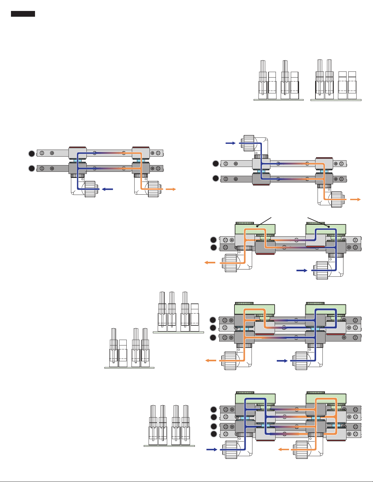
Using One RAM-35 Cooler and Serial vs. Parallel
When liquid cooling only one DIMM memory stick, nozzle confi guration is very simple. The RAM-35
requires one nozzle on each base for the inlet and outlet [Fig 4]. Sockets opposite these nozzles should
remain blocked with the included plugs, forcing liquid fl ow down through the Hydra-Paks. NOTE: Basic
serial confi gurations are not recommended for systems using internal tubing diameters larger than 1/4”
(6mm) for reasons detailed below.
Connecting each RAM-35 block in series is possible, but this is not recommended for most systems.
Physical motherboard space limits the volume of liquid that can be channeled between memory sticks. To help achieve a higher
overall fl ow rate, parallel confi gurations are preferred, particularly for systems using tubing diameters larger than 1/4” (6mm) ID.
Parallel confi gurations require at least two RAM-35 water blocks.
[Fig 4] Installed Nozzles
Page 2
Page 2
T o establish a parallel fl ow path, RAM-35 coolers force liquid through their Hydra-Paks while simultaneously passing it through
their nozzle bases. This means the coolant is effectively “split”, traveling through both Hydra-Pak and nozzle base.
The physical distance between memory sticks will determine which sliding nozzles are required to do this (topic covered later). With
any recommended group of RAM-35 water blocks, there will still only be a single inlet and outlet nozzle for tubing.
Using Two RAM-35 Coolers
Two memory sticks are typically arranged in alternating [Fig 5] or consecutive [Fig 6]
DIMM banks on the motherboard.
With memory sticks in alternating DIMM banks (or for consecutive banks spaced widely
enough apart), there will be room for a simple sliding nozzle between each base.
Two examples are shown. Fig 7 has inlet and outlet nozzles on the same side of the water
blocks. Fig 8 places these nozzles on opposite sides. Both are acceptable, and the fl ow
path is otherwise identical in these two examples.
1
2
1
2
[Fig 5] 2 x Sticks in
Alternating Banks
(Side View)
[Fig 6] 2 x Sticks in
Consecutive Banks
(Side View)
[Fig 7] Two RAM-35 with In/Out Nozzles on the Same Side
With memory sticks in consecutive DIMM banks, there is commonly no
room for the above confi gurations. Koolance has therefore designed
the RAM-35 with offset nozzle bases. When reversed, each nozzle
base will overlap the nearest RAM-35 cooler for a tighter fi t on the
motherboard.
To connect adjacent RAM-35 coolers in this situation, two Koolance
180° “U” blocks join each nozzle base [Fig 9].
Using Three RAM-35 Coolers
A recommended fl ow path with
three RAM-35 coolers is illustrated
in Fig 10. This effectively places all
three RAM-35 coolers in parallel.
3 x Sticks in Various
The distance between DIMM slots
will dictate which sliding nozzles
are required.
Banks (Side View)
[Fig 8] Two RAM-35 with In/Out Nozzles on Opposite
Sides
180° “U” Blocks
1
2
[Fig 9] Two Consecutive RAM-35
with 180° “U” Blocks
1
2
3
3 x Sticks in Various
Banks (Side View)
Using Four RAM-35 Coolers
A recommended fl ow path with four RAM-35
coolers is illustrated in Fig 11. This effectively
places all four RAM-35 coolers in parallel.
The distance between DIMM slots will dictate
which sliding nozzles are required.
4 x Sticks in
Consecutive Banks
(Side View)
[Fig 10] Three RAM-35 with 180° “U” Blocks
1
2
3
4
[Fig 11] Four Consecutive RAM-35 with 180° “U” Blocks
Page 3

Page 3
Using Five or More RAM-35 Coolers
[Fig 12] Eight Consecutive RAM-35
A greater number of RAM-35 coolers can be implemented with a
combination of basic fl ow paths. Generally, groupings are created of
up to eight water blocks, and each of these is connected in series.
Fig 12 illustrates a confi guration of eight RAM-35 coolers. There are
effectively two sets of four parallel paths, both connected in series.
Four parallel RAM-35 water blocks are the maximum recommended for
1
2
3
4
5
6
3/8” (10mm) and 1/2” (13mm) ID systems due to fl ow rate division.
7
With more than eight RAM-35 coolers, the second group should be
8
connected in series with the fi rst. This is done with sliding or regular
nozzles, depending on the motherboard’s DIMM slot layout.
How Sliding Connection Nozzles Work
There is little room between DIMM banks on a typical motherboard, and this distance also varies
by board model. As a result, Koolance has created a special type of sliding nozzle for use with
the RAM-35.
Sliding nozzles are adjustable “on the fl y”. There is no latching mechanism. This feature requires
care during assembly, even though a center bracket will help secure multiple RAM-35 water
blocks after mounting.
Koolance does not recommend adjusting RAM-35 water blocks when fi lled with liquid coolant. As with any water block, installation
should be done only with a dry system. When fi lled, RAM-35 water blocks pulled too far apart for their connecting nozzles will result
in a coolant leak.
Male (Left) and Female (Right) Sliding
Nozzles
CAUTION - Koolance does not recommend adjusting RAM-35 water blocks (or any water block) when fi lled with liquid
!
coolant. When fi lled, RAM-35 water blocks pulled too far apart for their connecting nozzles will result in a coolant leak.
Never pull apart RAM-35 sliding nozzles beyond their inner “safety line”.
To help avoid this, there are “safety lines” on
each sliding nozzle [Fig 13]. The second outer
line, if present, should be ignored-- it is beyond
the sealing point!
T o avoid leaks, never pull apart sliding nozzles
beyond their fi rst (inner) “safety line” [Fig 14].
[Fig 13] Male Sliding Nozzle Safety Lines
Determining Which Sliding Nozzles to Use
For multiple RAM-35 water blocks, the required sliding nozzles
will primarily depend upon the distance between memory sticks.
Measurements should be taken in millimeters, as mainboard
components are usually plotted with the metric system.
Begin measurement with your memory sticks installed in their
appropriate DIMM slots. Measure across, from the center of each
memory stick to the next [Fig 15].
First Inner Safety Line
Second Outer Line (Ignore!)
[Fig 14] Joined Sliding Nozzles Beyond
the First Inner Safety Line Will Leak!
[Fig 15] Measure Center Points Across Memory Sticks (in Millimeters)
Consider how each RAM-35 nozzle base will be connected with
the next. “Neighboring” nozzle bases [Fig 16] and “alternating”
nozzle bases [Fig 17] are the
only possibilities when using
sliding nozzles.
[Fig 17] Connecting “Alternating” Nozzle Bases[Fig 16] Connecting “Neighboring” Nozzle Bases
Page 4

Page 4
Memory center distances and nozzle base orientations should now be known. Koolance offers four
lengths of sliding nozzles. Nozzles should be chosen based on the distance between memory sticks
of connected RAM-35 coolers:
Model: CNT-ME0
Memory Distance:
16 - 19mm
Model: CNT-ME1
Memory Distance:
20 - 23mm
Model: CNT-ME2
Memory Distance:
24 - 27mm
Model: CNT-ME3
Memory Distance:
28 - 31mm
Model: CNT-MEU
Memory Distance:
8 - 10mm
For example, Fig 18 features two memory sticks 17mm apart in alternating banks. When using two RAM-35 blocks with “neighboring”
nozzle bases, the CNT-ME0 fi ts this distance best. A second example is Fig 19, which favors the CNT-ME2, plus CNT-MEU (180°
“U” Blocks) for the adjacent RAM-35 end connections.
17mm
CNT-ME0
[Fig 18]
26.3mm
[Fig 19]
CNT-MEU
CNT-ME2
Installation
CAUTION - To avoid leaks, every nozzle socket must include a red rubber O-ring. O-rings
!
can come loose. Always check for an even O-ring seal when installing a nozzle or plug.
To avoid leaks, every RAM-35 nozzle socket connection must include a red rubber O-ring. O-rings
can come loose and fall out. When misaligned, O-rings can also warp improperly or bulge outward
when compressed. Always ensure an even O-ring seal is present when tightening a nozzle or plug
on a RAM-35 nozzle base [Fig 20].
[Fig 20] Always Check for Red
O-rings in Every Nozzle Connection
with a female receptacle. Once nozzles and receptacles are in place, add the primary inlet and outlet
nozzles and any required 180° “U” Blocks.
Begin installation by screwing in the required nozzles and receptacles into
each RAM-35. For sliding nozzles, make sure every male side is paired
Male Nozzle
Female
Receptacle
Align this assembly over the motherboard DIMM
slots so that each memory stick will be gently
inserted between the Hydra-Pak folds of each
RAM-35 cooler [Fig 21]. As long as the coolers
are not fi lled with liquid, sliding nozzles can be
adjusted here for best alignment.
Push in each RAM-35 DIMM
latching arm and tighten gently
with a screw driver from the top [Fig 22]. This will
help hold the coolers in place on the motherboard
by hooking the DIMM locking tabs.
further movement of the sliding nozzles, a center wire bracket is
mounted across each RAM-35 water block. Tighten the included metal
center tabs of each RAM-35 to hold this wire in place [Fig 23].
[Fig 21] Aligning RAM-35 with memory
[Fig 22] Gently Tighten Each DIMM Latching Arm
To better-stabilize multiple RAM-35 coolers and avoid
Finally, trim the excess overhanging wire bracket as
needed with wire cutters [Fig 24].
[Fig 23] Tighten the Wire Bracket Tabs
[Fig 24] Trimming the Wire Bracket Tabs
 Loading...