

Page 1
1
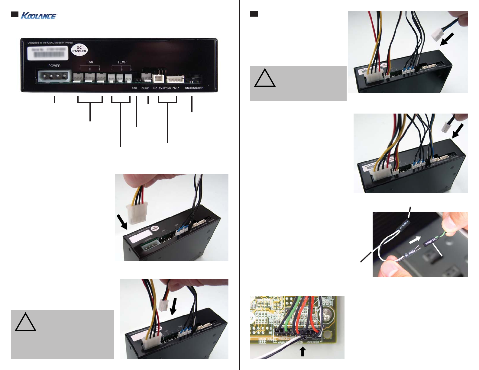
The rear of the unit accepts various connections to integrate with your cooling system.
CTR-CD12 User Manual v 1.0
2
Pump Connection
An external 12 Volt DC pump can be
connected to the unit for speed control.
The maximum available amperage is
2.2A.
CAUTION: This product
can be used with a single
!
12VDC pump with a maximum amperage of 2.2A.
POWER: Connection from
power supply, 12VDC
FAN: Radiator fan connections (2.0A max per
plug, 4.5A total)
TEMP: Temperature sensors
shown on the front display
Power Connection
The temperature sensors and ATX lead
may come pre-connected to your unit.
If not, connect them per the diagram
above.
Connect a 12 Volt 4-pin Molex plug from
the power supply to the power connection
on the rear of the unit.
Fan Connection
This unit has three connections to
power radiator fans. Multiple fans can
be combined into a single plug. (A fan
wiring harness is optionally available from
Koolance).
CAUTION: The total com-
bined amperage of all fans
!
connected to the unit can not
exceed 4.5A. The maximum
load on a single fan header
is 2.0A.
PUMP:
External
pump
ATX: Passthrough lead
for power shutdown feature
ON/SYNC/OFF:
Adjusts LED lighting
of INS-FM16 flow
meter
INS-FM17/INS-FM16:
Connect an optional flow
meter to display flow rate
Flow Meter Connection
The cooling system can show values
for one Koolance INS-FM16, INSFM17/N, or INS-FM18 flow meter
(sold separately). The use of a flow
meter is optional.
Connect a flow meter to the
appropriately labeled plug. (Note:
INS-FM18 should connect to the plug
labeled “INS-FM17”.)
ATX Pass-Through Lead
The ATX pass-through lead is
responsible for sending the shutdown signal if any sensor reaches the
preset shutdown temperature (See
Display Panel for configuration).
There is no polarity direction with
the ATX lead. Connect the male ATX
power lead from the cooling unit to
your computer’s main chassis power
button.
To Motherboard
From Cooling
Unit
Connect the female ATX power lead from
the Slot Adapter to the motherboard’s power
switch connection (often marked “PWRSW”,
“PWSW”, or “PWBT”).
This is the connection that would normally
receive the chassis power button directly.
Chassis Power
Button
Page 2
3
4
CAUTION: This product allows full user control of hardware safety settings,
!
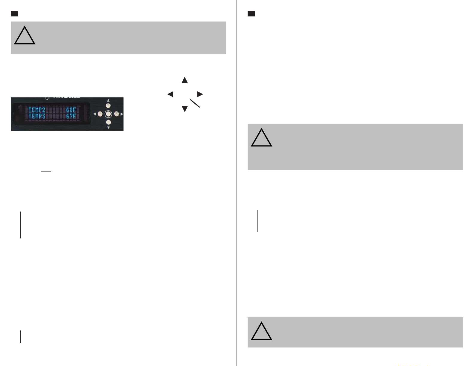
The Koolance display panel allows control and
monitoring of various aspects a cooling system.
4 buttons are used, with directional arrows to
navigate or change settings, and a center button
to enter/exit.
• On the main screen, hold ◙ for 3 seconds to change display units between
ºC/ºF and LPM/GPM.
• You can exit any menu and return to the main screen by holding
seconds.
• To reset ALL settings to default, hold ▼ + ▲ for 5 seconds.
Main Menu
To enter the main menu, briefly press
▲ to navigate this menu.
▲
TEMP SET: Temperature, alarm, and shutdown settings
FAN SET: Fan settings
PUMP SET: Pump settings
FLOW SET: Flow meter settings
DISPLAY SET: Display settings
▼
When in the top menu, press ◙ to enter one of the above categories. To exit from here,
press ◄.
TEMP SET
The temperature menu allows configuration of the alarm and safety shutdown options. This
cooling
sound if any sensor reaches its set alarm point. The offending sensor will also flash in the
display, and the radiator fans and pump will increase to 100% power. If any sensor reaches
its set shutdown point, the system will shutdown power to the computer via relay using the
“ATX pass-through” wire.
▲
TEMP1 55C 56C : Sensor #1, Alarm Point, Shutdown Point
TEMP2 51C 54C : Sensor #2, Alarm Point, Shutdown Point
such as audio alarm, shutdown, and pump speed. Please be sure to configure
your Display Panel properly, or damage to your computer, data, and/or equipment could result.
Navigate Up,
Increase Setting
Navigate
Left
◙
Navigate Down,
Decrease Setting
Navigate
Right
Enter/Exit
◙ for 2
◙. The selected option will begin flashing. Use ▼ and
system can monitor up to 3 (included) temperature sensors. An audio alarm will
▼
When in the “Temperature Settings” menu, the selected temperature sensor will flash. Press
▼ and ▲ to navigate, or press ◙ to select a sensor to configure:
TEMP1 SET
AL: 55C PW: 56C : AL = Alarm, PW = Power (Shutdown)
The alarm value will flash. Press ▼ or ▲ to adjust a value. Press ◙ to change to the
shutdown temperature. Press
to the previous menu.
NOTE: The shutdown temperature must be at least 1ºC (1-2ºF) higher than the alarm
temperature. If an alarm temperature can not be increased, increase the shutdown
temperature first. The minimum and maximum temperature range allowable is 0-99ºC (32210ºF).
CAUTION: Generally, sensors report liquid temperature at the water block,
!
FAN SET
This unit has three fan channels which can be independently adjusted. Alternatively, use the
master fan channel (“ALL FANS”) to adjust all fan channels simultaneously.
▲
ALL FANS 50% : All Fans (Master), Speed Setting %
FAN1 SET 84% : Fan Channel #1, Speed Setting %
FAN2 SET 47% : Fan Channel #2, Speed Setting %
FAN3 SET 30% : Fan Channel #3, Speed Setting %
▼
The selected fan channel will flash. Press
previous menu,
ALL FANS 50%
The speed value will flash. Press ▼ or ▲ to adjust this value. Press ◙ to confirm the
setting.
Higher fan speeds can improve performance, but will produce more noise. Fan speeds can
be adjusted manually from 0-100%.
!
which is typically 5-10°C (9-18°F) lower than the actual heat source. This difference must be considered if adjusting alarm/shutdown temperatures. Setting
alarm/shutdown modes at too high of temperature can eliminate this feature’s
effectiveness. The default Koolance settings are designed to help compensate
for differences in temp.
or press ◙ to configure this fan channel:
CAUTION: Fan percentages are based on PWM duty. Fans will not operate
if set too low. Some types of fans may also not be compatible with the PWM
program and will only operate reliably at 100%.
◙ again to exit configuration of this sensor. Press ◄ to return
▼ and ▲ to navigate, press ◄ to return to the
Page 3

5
6
Instead of manual speeds, fans can also be set to automatic. This is highly recommended,
since speeds will change based on temperature sensor feedback. This is a good way to keep
noise levels to a minimum while allowing the cooling system to respond to temperature. To
set a fan channel to automatic, press ▲ past 100% until “AUTO” is shown:
ALL FANS AUTO
From here, press
ALL FANS AUTO
T1 L45C H80C : Temp Sensor, Low Point, High Point
The number following “T” designates the temperature sensor this fan channel will follow.
When flashing, press
option.
The number following “L” is the temperature low point. The number following “H” is the
temperature high point. Automatic fan control will adjust fans on a dynamic ramp between
these two points:
Automatic Fan
When the temperature low point is flashing, press
the temperature high point, and press
previous menu.
PUMP SET
The pump speed can be manually set from 1-10:
PUMP(1-10) 7LV : Pump Speed Level
The pump speed level will flash. Press
menu.
FLOW SET
◙ to configure the automatic mode:
▼ or ▲ to change sensors (1-3). Press ◙ to move to the next
100%
Power
20%
(Low Point)
▼ or ▲ to adjust it. Press ◙ again to return to the
▼ or ▲ to adjust. Press ◙ to return to the previous
42ºC
▼ or ▲ to adjust it. Press ◙ to move to
60ºC
(High Point)
The Koolance flow meter model number (SKU) will flash. Press ▼ or ▲ to adjust this based
on the following:
• INS-FM16: change to “FM-16”
• INS-FM17, INS-FM17N, INS-FM18: change to “FM-17”
Press ◙ to move to the next option. The tubing internal diameter (ID) size will flash. This
refers to the hose size attached to the flow meter itself. Press ▼ or ▲ to adjust this based
on the following:
• 6mm (1/4 inch): change to “ID: 6mm”
• 10mm (3/8 inch): change to “ID: 10mm”
• 13mm (1/2 inch): change to “ID: 13mm”
Press ◙ to return to the previous menu.
DISPLAY SET
The display settings configure which values you wish to appear on the front display and how
they are shown:
DISPLAY
FIXED CYCLIC : Show 2 values or cycle multiple values
The first option, “FIXED”, will flash. Press
◄ or ► to change between these options. Press
◙ to configure one of the selections, or press ▲ to exit. If “FIXED” is selected, two lines will
be shown:
TEMP1 21.7C : First line display option
TEMP1 21.7C : Second line display option
The first line will flash. Press
TEMP1 21.7C : Show temperature sensor #1
▲
TEMP2 21.2C : Show temperature sensor #2
TEMP3 20.8C : Show temperature sensor #3
FAN1 1770RPM : Show fan channel #1
FAN2 1640RPM : Show fan channel #2
FAN3 1820RPM : Show fan channel #3
PUMP 5730RPM : Show pump speed
FLOW 4.1LPM: Show flow rate
▼
Press
◙ to confirm. The second line will flash. Press ▼ or ▲ to adjust this line.
Press ◄ to return to the previous menu, or press ◙ to return to the main screen.
▼ or ▲ to change what this line will display:
If a Koolance flow meter (sold separately) has been connected to the slot interface adapter,
configuration is needed to properly display its values. Only one flow meter can be displayed
by the cooling system.
FLOW METER SET
FM-17 ID: 10mm : Flow Meter Model, Tubing Internal Diameter
When “FIXED” is the chosen display option, line 1 and 2 can be changed quickly without
reentering the DISPLAY SET menu. To do this, briefly press ▲ from the main screen. The
first line will flash:
TEMP1 21.7C : First line display option
PUMP 5400RPM : Second line display option
Page 4

7
Press ▼ or ▲ to change what this line will display among the options described earlier.
Press
◙ to move to line 2, and similarly use ▼ or ▲. Press ◙ again to exit.
If “CYCLIC” is chosen from the DISPLAY SET menu, multiple values will be rotated through
the front display. The first option is whether these values will cycle vertically or horizontally
through the display:
CYCLIC
VERT HORI: Rotate values vertically or horizontally
The first option, “VERT”, will flash. Press
◄ or ► to change between these options, press
◙ to configure a selection, or press ▲ to exit. Choosing either option with ◙ will list all
available values:
▲
*TEMP1 21.7C : Show temperature sensor #1
*TEMP2 21.2C : Show temperature sensor #2
*TEMP3 20.8C : Show temperature sensor #3
*FAN1 1770RPM : Show fan channel #1
*FAN2 1640RPM : Show fan channel #2
*FAN3 1820RPM : Show fan channel #3
*PUMP 5730RPM : Show pump speed
*FLOW 4.1LPM: Show flow rate
▼
The selected line will flash. Use
disable each value. This will remove the asterisk, thereby hiding that line from being shown
on the main screen:
▲
*TEMP1 21.7C : (shown)
*TEMP2 21.2C : (shown)
*TEMP3 20.8C : (not shown)
*FAN1 1770RPM : (shown)
*FAN2 1640RPM : (not shown)
*FAN3 1820RPM : (not shown)
*PUMP 5730RPM : (shown)
*FLOW 4.1LPM: (shown)
▼
Press
◄ to return to the previous menu, or press ► to exit DISPLAY SET.
▼ and ▲ to navigate to other lines. Press ◙ to enable or
This page is intentionally left blank.
Temperature Sensor Placement
Three surface temperature sensors are included
with this product for monitoring. Generally,
sensors are affixed to water blocks with metal tape.
(Liquid temperature sensors are also available
optionally from Koolance.)
Sensors should never be placed directly
between a heat source and its water block. This
will interfere with contact and can damage the
sensor or heat source.
Chip contact
area
(keep out)
 Loading...