

Page 1
1
1.
2.
3.
4.
CPU-360, CPU-370 Installation Guide v 1.1
CAUTION: Be sure to attach a Koolance system temperature probe
(if available) to the CPU cooler during installation. Koolance system
!
safety features may not function properly without the correct placement
of this probe, and hardware damage can result.
Install two G 1/4 BSP threaded nozzles (sold separately) into
the cooling block. Hand tighten all nozzles-- overtightening
can damage the block and threads.
Remove any protective film from
the bottom of the cold plate.
If a Koolance system is used,
place the temperature sensor
included with it on the edge or
side of the water block’s metal
cold plate. Make sure it is not
covering any area that will be in
contact with the CPU.
DO NOT attempt to install the temperature probe in
between the processor and cooler. Despite its thin size, it
will interfere with CPU contact or burn-out the sensor.
Trim out a piece of metal tape and apply it to keep the
temperature probe in place. DO NOT stick metal tape or
the temperature probe where the processor comes in
contact with the cooler.
You can use a zip-tie to further secure the temperature
probe wire to the CPU water block’s tubing.
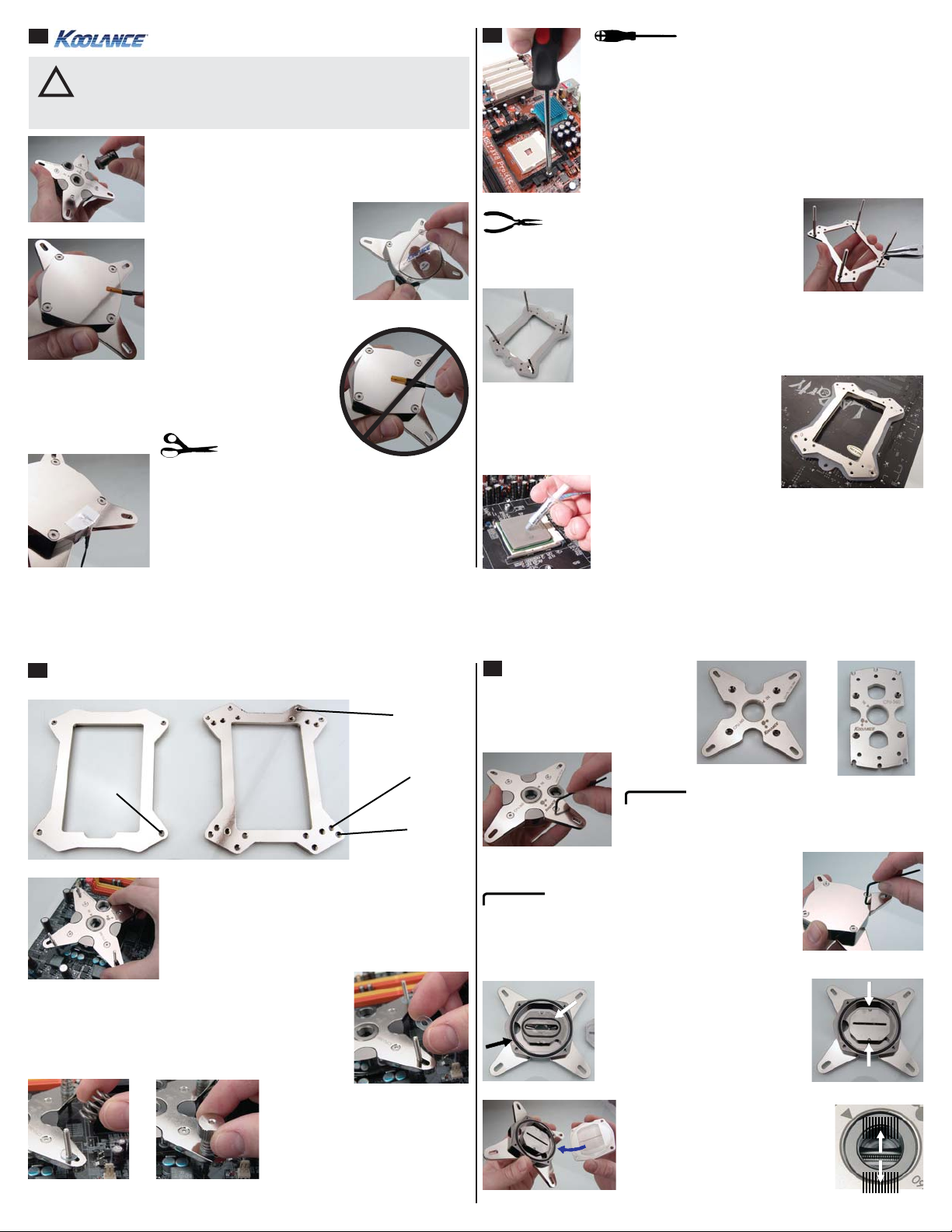
2
Some processors, like AMD sockets AM2/
AM2+/AM3, may require removal of the
motherboard’s existing retention frame in order to install the
Koolance water block.
If present, remove this retention frame by unscrewing its
screws, or if plastic tabs are used, pulling out these locking
tabs.
(Refer to bracket images on the following page for specific
CPU post positioning.)
Threaded posts are screwed directly into
the CPU block’s rear bracket. Pliers or
a small wrench may be required to fully
tighten the posts.
Place the rubber insulation pad over the bracket posts. This
helps to protect the motherboard from damage and electrical
shorting from the back plate.
From beneath the CPU socket, carefully insert the
back plate posts through the motherboard mounting
holes. The insulating pad will be sandwiched between
the back plate and motherboard.
Apply thermal paste to the CPU directly. Spread the paste
so that it evenly and thinly covers the CPU. A piece of thick
paper (such as a business card) works well for this.
Two back plates may be included with your water block. Use the below
3
diagrams to determine which holes your mounting posts must use.
AMD Socket
AM2, AM2+, AM3
Intel Socket
LGA 1156, 1155
Place the water block over the mounting posts. If
another top bracket is needed for your CPU, see
details later on changing this.
The temperature sensor should already be installed
on the cooler (if available).
Install the optional plastic washers over each post. These
help protect the metal bracket from becoming scratched.
Place retention springs, and then
thumb nuts on each post.
Gradually tighten each thumb nut by
hand. DO NOT OVERTIGHTEN!
Place Springs
Tighten Thumb Nuts
Intel Socket
LGA 775
Intel Socket
LGA 1366
4
Changing the Top Bracket
Two top brackets are included with the water
block. Use the bracket that matches your
CPU socket type.
Intel LGA 775, 1156/1155,
1366 Bracket
To remove or replace the CPU mounting bracket, loosen the
four top screws with the included wrench.
Opening the Water Block
The CPU water block can be opened (for cleaning,
screws with the included wrench.
It is extremely important to reassemble the water block properly!
There are several things to check:
1.
3.
etc.) by carefully unscrewing the four bottom
1. Make sure both o-rings are smoothly
in their grooves. These should never
become warped or damaged.
2. The center impingement plate has side
notches to align it with two metal tabs on
the top cover.
3. The cold plate microfins must run
perpendicular to the impingement
plate slot!
4. When the block is assembled, look
down into the inlet hole to confirm proper
fin direction. The microfins should look
like a zipper.
AMD AM2/AM2+/AM3
Bracket
2.
4.
 Loading...