

Konvision KFM-5X series, KFM-6X series User Manual

KFM-5X series / KFM-6X series LCD Monitors
USER MANUAL V2.1
Shenzhen Konvision Technology Co., Ltd
http://www.konvision.com

Shenzhen Konvision Technology Co,.Ltd www.konvision.com
Contents
Notes ........................................................................................................................ 3
Security .................................................................................................................... 4
Features ................................................................................................................... 6
Parts and Functions ............................................................................................. 10
A: Front View ................................................................................................. 10
B: Rear View ................................................................................................. 14
Menu Operation .................................................................................................... 18
Menu Item Description ................................................................................. 19
1. Main menu: ............................................................................................... 19
2. Sub Menu: ................................................................................................. 20
Status: .................................................................................................... 20
Function Key: ........................................................................................ 21
Picture Setting: ...................................................................................... 23
Image: .................................................................................................... 24
Audio: ..................................................................................................... 27
Marker Setting: ...................................................................................... 29
Scope: .................................................................................................... 31
Embedded code: .................................................................................. 33
Layout: ................................................................................................... 34
IMD: ........................................................................................................ 39
Alarm: ..................................................................................................... 42
Setup: ..................................................................................................... 44
Key Lock: ............................................................................................... 46
3. Function Key ............................................................................................. 47
SDI 2K signal display Description: ..................................................................... 49
Factory Reset ........................................................................................................ 49
Remote Control ..................................................................................................... 51
Rack quick installation process .......................................................................... 51
2

Shenzhen Konvision Technology Co,.Ltd www.konvision.com
Notes
For the safety use of products, please read the following instructions
regarding the installation, use and maintenance carefully.
. Please read the product safety and operating instructions carefully before the product is
operated.
. Please keep the safety and operating instructions for future reference.
. Please pay strict attentio n to the warnings and implement the products ac cord in g to the
operating instruct ions closely.
. All operating instruct ions should be strictly enforced.
1. Please use the power cord recomm en d ed by man uf acturer.
2. Please do not place he avy objects on the power cord.
3. Please do not expose the monitors to rain, humid, dusty places.
4. Please do not place vesse l s wit h li qu i d (s uch as cu ps, beverage bottles) on the
monitor.
5. Please do not place t h is product in high heat places.
6. Please make sure the earth terminal is good in order to a v oi d el ectric shock.
7. Please do not open the back cover to avoid electric shock. Please contact
professionals for service need.
8. If there is no image or sound, please unplug the power cord from the AC outlet
immediately. Please c onsult profession a ls if t here still have problems after examining
carefully.
9. Do not place this product at unstable places such as cars, shelves or tables, as it is
easy to make the product falling down, may cause severely hurt to children and adults
and also damage to the pr od uct.
10. Please do not touch the power plug with wet hands, as it will cause electric shock.
11. Please do not expose the LCD panel in direct sunlight for a long time, it will result in
damage or aging of t he LCD panel.
12. Please display this pro duct at a suitable tempera ture and humidity place.
13. Please do not spray any liquid things and/or add any objects into the monitor, it might
3

Shenzhen Konvision Technology Co,.Ltd www.konvision.com
cause voltage instability and short-circuit, also can easily cause fires and blackouts.
14. If do not use the device for a long time, please unplug the pow er cord from the AC
outlet.
15. Please keep not less than 5cm space around the vents while using the monitor, in
order to obtain good heat diss i pation effect.
Security
Screen Maintenance
Please follow the below guidelines carefully to prevent discoloration, stains and scratches
on the screen:
- Avoid striking the screen with any obj ect.
- Do not wipe the screen hard.
- Do not wipe the screen with solvents such as alcohol, thinner or gasoline.
- Do not spray detergent or other cleaners on the monitor or LCD panel, as it may cause
fault because of water dr oplets into the monitor.
- Do not write on the screen.
- Do not paste or stick any viscous markers on the scre en.
Screen may be cleaned by gently wiping with lint free cloth to remove dust. For the more
difficult cleaning, use lint free cloth that has been very lightly dampened with detergent,
then dry any excess moisture from the mo ni t or or LCD panel immediately to prevent
damage.
Cabinet Ma intenance
Please follow the guidelines below to prevent potential damage.
- Do not wipe the cabinet with solvents such as alcohol, thinner or gasoline.
- Do not use any pesticides and/or other volatile substances.
- Do not allow prolonged contact with rubber or plastic.
- Do not wipe the cabinet hard. Use a soft, lint free cloth to clean. If the cabinet cleaning is
more difficult, use li nt fre e c l oth that has been very lightly damp en e d wi th detergent and
then dry it to wipe.
4

Shenzhen Konvision Technology Co,.Ltd www.konvision.com
Installation
- Keep adequate air circulation to prevent device internal overheating. Please do not
place the product on the surface of some certain objects (such as blankets, carpets,
etc.), as these objects may block the vents.
- Please keep the device away from heat generating sources, such as radiator, heaters
and air duct, also keep it away from much dust or mechanical vibration place.
Rack mount Installation
- For rack mount installatio n, please keep 1U space from both top and bottom to make
sure adequate ai r circulation, or install an ex ternal electric fan. Please follow th e
instructions and install with the rack mounts provided by manufacturer.
Transportation
- This monitor is precise equipm en t a n d n e ed pro fessional packing ma terials to transport.
So do not to use packing materials pr ovi de d b y supp li ers exc ept KONVISION or its
authorized packing material suppliers.
When the following situations occur, please turn off the power, do not
insert the plug and contact a professional service staff to deal with
timely.
A. This product smells smoke and off-flavor.
B. When this product displays abnormal operating conditions, such as there is no picture
or sound.
C. When any liquid is splashed into the product or product dropped.
D. When the product soaked or fall into the water.
E. When the product has been damaged or other damage circumstance s.
F. When the power cord or plug is damaged.
5

Shenzhen Konvision Technology Co,.Ltd www.konvision.com
The following does not belong to failures:
1. If the static image dis p layed too long, it will have res i dual image, which shoul d be
attributed to the charac teristics of LCD display but not a failure . Residual image will
disappear automatically after a period of time.
2. If this device used in a cold environment, the scre en may app ear residual image.
This is not a product failure, wh en the monitor temperature changes, screen will
return to normal conditions.
3. LCD screen may appear tiny spots (red , blue or green), this is not a fa ul t, LC D
screens are manufactured with high precision technology, and a small number of
pixels may not be able to show intermittent.
4. Screen and cabinet will become warm gradually during operating.
Features
High Brightness LCD Panel
- High brightne ss, high contr ast, hig h-speed respons e and wide view ing a ngle tec hnolog y
makes the monitor can be used under variety of lighting conditions.
High Brightness Tally Indicator
- The tally function via GPT or LAN port, with two colors red and green.
Auto-detection of all color system (PAL, NTSC, SECAM)
- This unit detects the color system automatically.
3D Video Decoder
- Process 3D decoding on VIDEO signals, to realize better reduce cross color.
Motion-Adaptive Interlace to Progressive
- It converts interlaced video to progressive video by motion detection, reduce the
serrated image
10BIT Signal Processing
- Signal input, signal pr ocessing and image output are 10bit data processing, to ensure
the details display of the image.
6

Shenzhen Konvision Technology Co,.Ltd www.konvision.com
Support Multiformat SDI Signals
- The SDI interface supports SD-SDI, HD-SDI, dual link HD-SDI and 3G SDI inputs.
SDI Input
- Support multi-format SDI input, SD-SDI, HD-SDI, 3G SDI
- Support SMPTE425M-A/B 4:4:4 signals.
HDMI/DVI/VGA Input
- HDMI signal can be input via HDMI to DVI-I converter through DVI connector, DVI
signal can be input through DVI connector, VGA signal can be input via VGA to DVI-I
Converter through DVI connector.
Signal Source Loop Through
- Signal that linked to the input connector will be enlarged and linked to output
connector. SDI re clock loop out ensure the signal with out enervation.
PIP/PBP
- Two SDI inputs signals display simultaneously under PIP (picture in picture) and PBP
(picture by picture) mode. One SDI input signal can be also displayed with another
signal of VIDEO, S-VIDEO, COMPONENT, HDMI simultaneously, and showing two
pictures on the screen.
SWAP Function
- In PIP/PBP mode, two pictures can be swapped between each other.
Color Temperature
- Different color temperatures can be selected freely
Image Size Setting
- The display mode is switchable among 16:9, 4:3, full screen, 1:1, and the original
image proportion.
Marker Setting
- Show frame borders, center marker, and s a fety area, etc.
HV Delay
- Display horizonta l an d vertical board and b l anking area of SDI1 in pu t s ig n al .
7

Shenzhen Konvision Technology Co,.Ltd www.konvision.com
Color Space
- Color space include: Rec 709、EBU、DCI P3 D65、DCI P3、Rec 2020、USER1、USER2、
USER3. (This function only available to KFM-6X)
Color Calibration
- This enable to calibrate imported color data of the image being measured by color
analyzer. (This function only available to KFM-6X, specific instructions please contact
with the dealer.)
Scan Mode
- Scan mode includes Full Scan, Over Scan, Under Scan.
Part Zoom In
- Zoom in any part of the picture, to watch picture details more clearly, and assist for
focus.
Audio level meter (UV+PPM)
- Show the audio level meter (UV+PPM) for SDI embedded audio.
Waveform
- Display input signal waveform and color scope for SDI signal input monitoring. It
includes luminanc e w avef orm , CbCr w avefor m. L umina nce wav eform wil l mark w ith r ed if
over the value specified by user.
Focus Assist
- Focus assist is to aid the cameraman focus on the main body by marking the
sharpest edge of th e ima g e wi th r ed .
False Color
- False color can Intuitively observe and calculate illumination level in the image,
luminance and ill umi na t io n v alues display mapping as lumi n ance level, from darkest to
brightness display blue, cyan, green, yellow, orange and red in turn.
Histogram
- YRGB histogram displays the hue distribution of the entire image under SDI input
condition, can intuitively display exposure of the image, display R, G, B 3 channels
independently.
8

Shenzhen Konvision Technology Co,.Ltd www.konvision.com
Vector scope
- Vector UV analysis for color bar signal input.
Pixel Measurement
- User can measure any pixel’s specific position and RGB value, also can compare the
YRGB value between any 2 pixels.
Time code
- Display SMPTE time code (LTC, VITC1, VITC2) under SDI1 input, it is used for
identifying and synchr on iz in g of v ideo data streams.
Remote Control Function
- Available to connect to the remote terminal to operate the equipment directly, select
the input signal, longi tudinal mode settings and tally indicator, etc.
9
Shenzhen Konvision Technology Co,.Ltd www.konvision.com
Parts and Functions
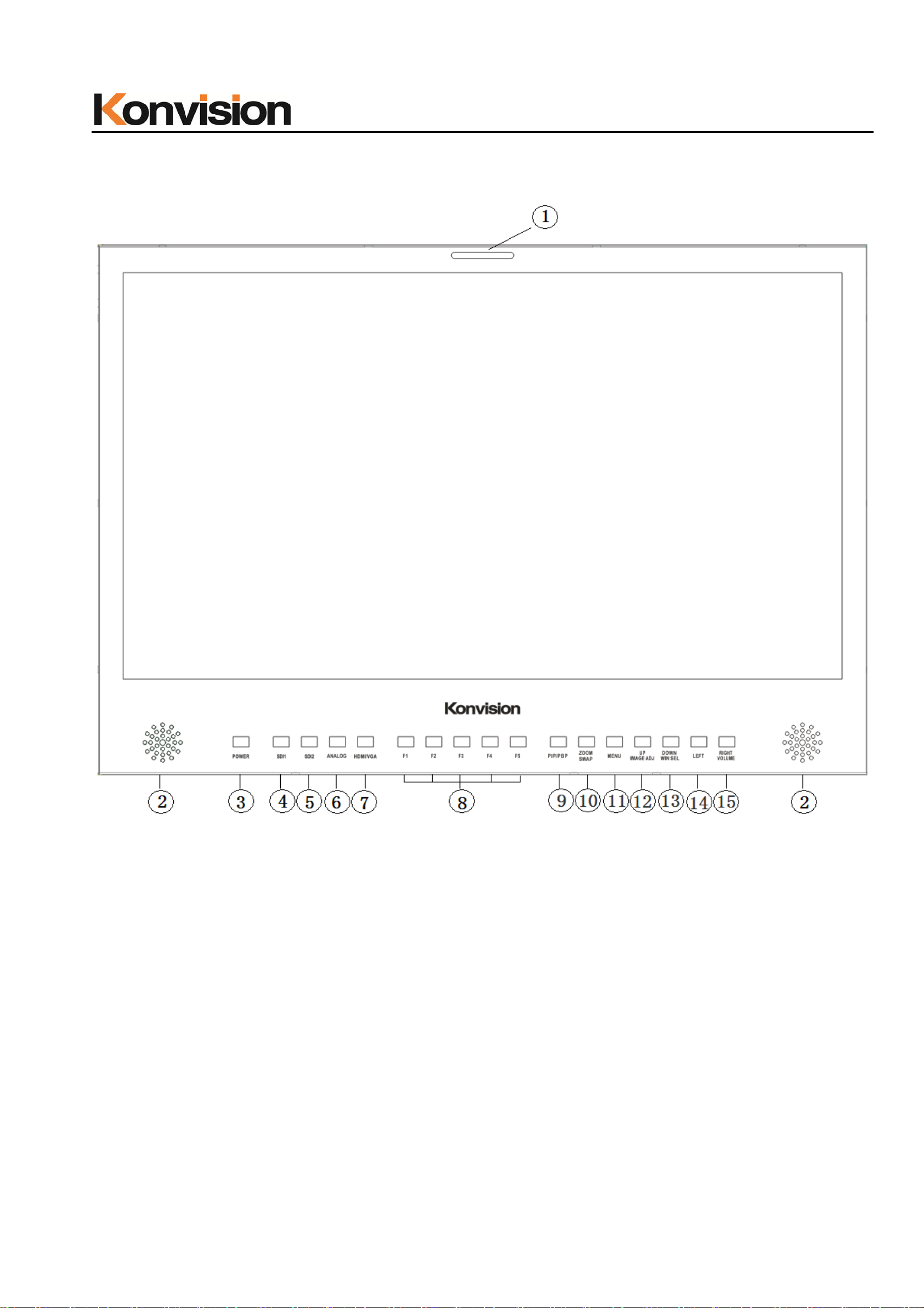
A: Front View
(1)Tally Indicator
Control method of Tall y light
1. GPI port(control method: pl ease look the GPI port descriptio n)
2. RS422 Port: support use TSL3.1 or TSL 4.0 protocol control the tally light
(2) Speaker
Stereo audio output.
10

Shenzhen Konvision Technology Co,.Ltd www.konvision.com
(3) Power Button and Indicator
When the external AC power supply with electricity, the indicator light is red. Press
this POWER button to power on the monitor, and the indicator light turns blue. Press this
button for about 2 seconds, can turn off the monitor, the ind ic ato r light turn red.
(4) SDI1 Button and Indicator
Press this button to select SDI1 signal input, indicator turns blue.
(5) SDI2 Button and Indicator
Press this button to select SDI2 signal input, indicator turns blue.
(6) ANALOG Button and Indicator Light
Press this button to select input signal between YPb P r 、Video、 S-video, indicator
turns blue.
(7) HDMI/VGA Button and Indicator Light
Press this button to select signal input among DVI/HDMI/VGA, indicator turns blue.
(8) F1-F5 Button and Indicator Light
F1-F5 these buttons can be used as shortcut buttons.
Press the F1-F5 buttons to select the corresponding function.\
When the set button function item is set to off in the main menu, this buttons are
invalid.
F1-F5 These button functions can be set in the menu Function key options.
(9) PIP/PBP Bu tton
Press this button for window layout among single, PIP, PBP mode. In PIP/PBP
mode, one of the signal must be SDI1 input, the other can be any of SDI2, HDMI,
VGA, Video, etc.
(10) ZOOM/SWAP Button
At single mode: press this button to zoom in
At PIP/PBP mode: press this button to swap 2 windows rapidly.
11

Shenzhen Konvision Technology Co,.Ltd www.konvision.com
(11) MENU Button
Press this button to display the OSD menu, and press it again to exit the menu.
Clear the Marker display.
Clear Display mode.
Turn off the shortcut menu.
(12) UP/IMAGE ADJ Button
When in OSD main menu, press this button to select up sub-men us.
When not in OS D menu, pr ess this button t o show back light , brig htness, and contrast
respectively.
The display has the following changes:
Backlight: The screen backlight brightness adjustment shortcut menu display, press
the LEFT button or (RIGHT / VOLUME) button to adjust the brightness of the screen
backlight.
Brightness: The image brightness adjustment shortcut menu is displayed. Press the
LEFT button or the (RIGHT / VOLUME) button again to adjust the image brightness.
Contrast: The image contrast adjustment shortcut menu is displayed. Press the
LEFT button or the (RIGHT / VOL UME) but t on again to adjust the image cont rast.
(13) DOWN/WIN SEL Button
When entering the men u op eration, press to select the me nu item.
When the screen is in the PIP / PBP state, press this button to select one of the
picture. In this case, you can press other buttons to set the parameters of the selected
screen independently, without affecting the parameters of the other screen.
(14) LEFT Button
When entering the menu operation, press this button to select the menu item.
When not in the menu opera ti on, pr ess th is button to enter the volume adjustment
shortcut menu.
When entering the shortcut menu, press this key to adjust the scroll bar to the left.
12

Shenzhen Konvision Technology Co,.Ltd www.konvision.com
(15) RIGHT/VOLUME Button
When entering the main menu operation, press this button to select the sub menu
to the right.
When entering the sub menu operat i o n, press this button to adjust the p arameters
of the current sub menu item to the right.
When not in th e menu oper ation, pr ess this butt on to ent er the vo lume adju stment
shortcut menu.
When entering the shortcut menu, press this button to adjust the scroll bar to the
right.
13
Shenzhen Konvision Technology Co,.Ltd www.konvision.com
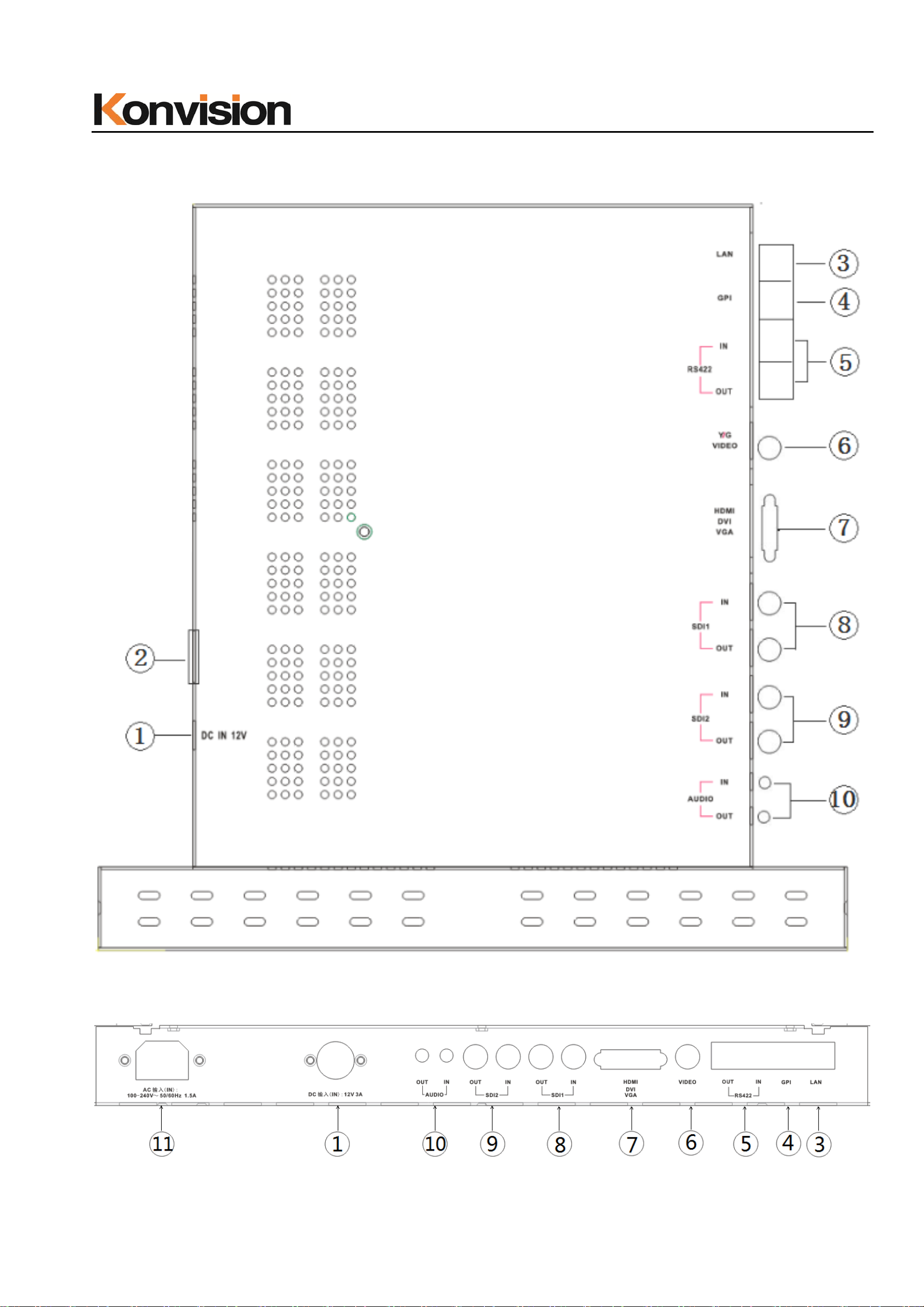
B: Rear View
KFM-1753W rear view port
KFM-1760D rear view port
14

(1) DC 12V IN
12V DC power supply
Shenzhen Konvision Technology Co,.Ltd www.konvision.com
The interface pins are defined as:
Pin 1: Ground
Pin 2: NC
Pin 3: NC
Pin 4: +12V
(2) ON/OFF
Power button
(3) LAN
In shortcut functions: Turn the knob to adjust the value of Brightness, Contrast and
Chroma respectively.
Ethernet port for remote network control. Thought this port, along with software
“Konvision Device Controller”, you can achieve remote controlling to the monitor
easily. (remote control software & instructions please contact with the dealer)
15

(4) GPI
GPI interface:
Shenzhen Konvision Technology Co,.Ltd www.konvision.com
Pin GPI Signal Description
1 GPI1 when connect GND, GPI1 works, GPI1 function can be
set in the menu function option
2 GPI2 when connect GND, GPI2 works, GPI2 function can be
set in the menu function option
3 GPI3 when connect GND, GPI3 works, GPI3 function can be
set in the menu function option
4 TX RS232-TX, for MCU program upgrade, please contact
the dealer for upgrade operation.
When the program is not upgr aded, the suspens ion is not
connect.
5 RX RS232-RX, for MCU program upgrade, please contact
the dealer for upgrade operation.
When the program is not upgr aded, t he suspens ion is no t
connect.
6 GPI4 when connect GND, GPI4 works, GPI4 function can be
set in the menu function option
7 NC Not connect
8 GND Ground
16
 Loading...