


IA
KONTRON
INSTRUMENTS
HPLC
GRADIENT
FORMER
Instruction
manual

-K
Instruction manual
GRADIENT
FORMER
425
HPLC
*-~\4
Checking
TABLE
1.l
OF
CONTENTS
INSTALLATION
Unpacking
1.2
Shipping
1.3
Checking
the
l.5
Installation
1.5.1 Pump
1.5.2
1.5.3
1.5.4
1.5.5
1.5.6
2
list
2
the
serial
mains
Installing
Liquid
Electrical
Gas
Control
supply
4
modification
connections
purge
Computer
number
3
the
gradient former
connection
7
3
4
5
6
6
7
page
2.
INSTRUMENT
General description
2.1
Specifications
2.2
Front
panel
2.2.1 Controls
2.2.2 Status display
DESCRIPTION
2
2
3
3
3
11.86
0
GENERAL INFORMATION
- l -

Instruction
manual
GRADIENT
FORMER
425
HPLC
TABLE
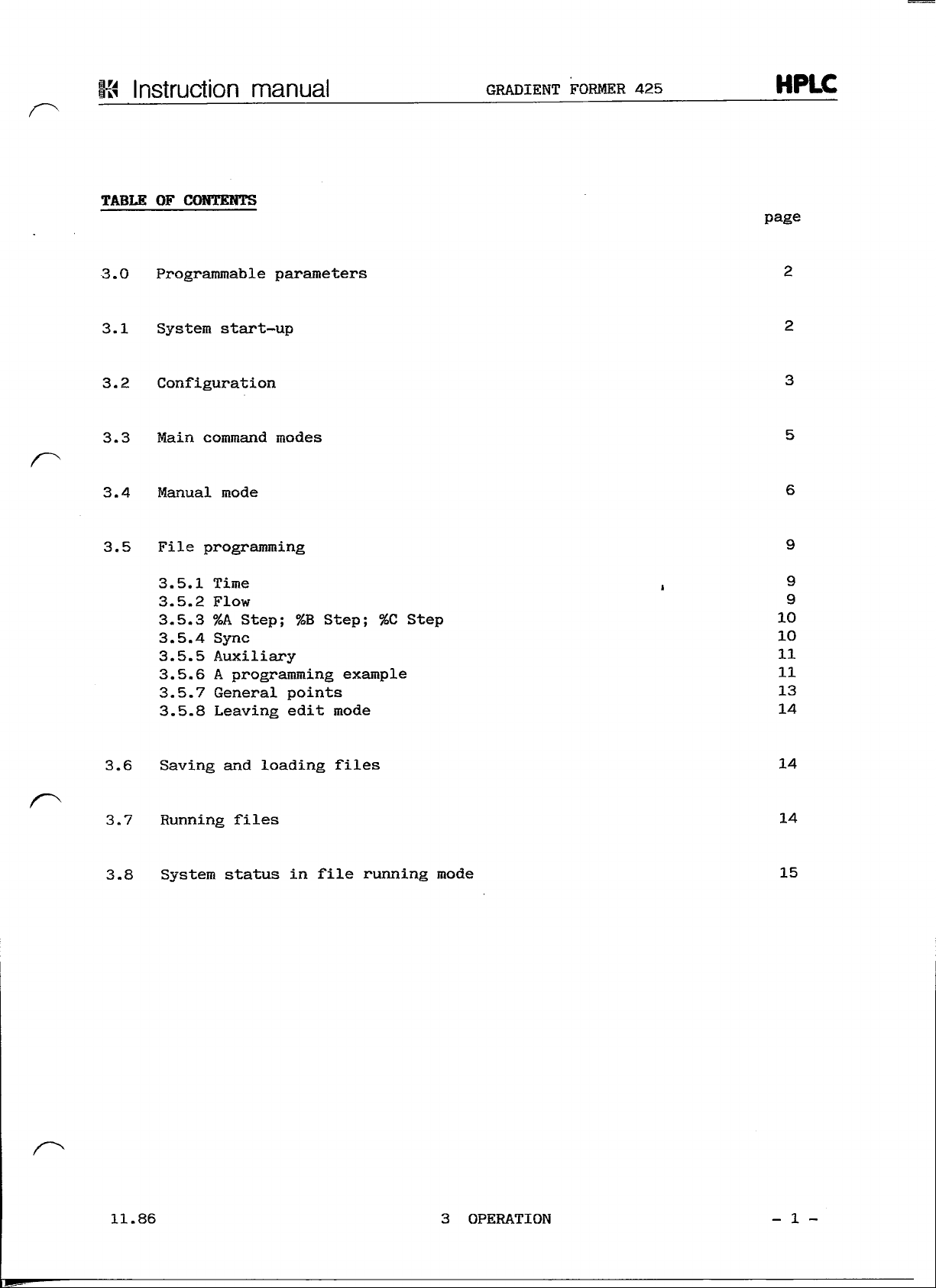
3.0
3.1
OF
CONTENTS
OPERATION
Programmable
System
3.2
Configuration
3.3
Main
3.4
Manual
3.5
File
command
programming
3.5.1 Time
3.5.2
3.5.3
3.5.4 Sync
3.5.5
3.5.6 A programming example
3.5.7
3.5.8
(cont.)
parameters
start-up
modes
mode
6
9
Flow
9
%A
Step;
10
Auxiliary
General
Leaving
2
2
3
5
9
%B
Step;
11
points
edit
mode
%C
Step
10
11
13
14
page
3.6
Saving
3.7
Running
3.8
System Status
4.
TROUBLE
4.1
Operation errors
4.2
Software error
5.
MAINTENANCE
5.1
Routine
5.2
Spare
and
files
SHOOTING
maintenance
parts
loading
in
3
files
14
file
2
messages
14
running
3
2
mode
15
11.86
0
GENERAL INFORMATION
- 2 -

13
Instruction
manual
GRADIENT
FORMER
425
HPLC
TABLE
l.
1.l
1.2
1.3
1.4
OF
CONTENTS
INSTALLATION
ünpacking
Shipping
Checking
Checking
1.5
Installation
1.5.1 Pump
2
list
2
the
serial
the
mains supply
4
modification
number
3
3
4
page
1.5.2
1.5.3
1.5.4
1.5.5
1.5.6
Installing
Liquid connections
Electrical
Gas
purge
Control
the
gradient former
connection
7
Computer
7
5
6
6
11.86
l
INSTALLATION
- l -

Ki
Instruction
TL.
INSTALLATION
1.1
UNPACKING
manual
GRADIENT
FORMER
425
HPLC
Compare
main
following
immediately
1.2
SHIPPING
The
1
2 m
1
2
2
3
l
6
l
l
l
l
l
l
l
the
consignment
unit
following
91-00553
07-89023
55-65601
62-13001
62-13002
66-00452
91-00560
92-00910
92-00904
93-00667
93-00668
95-00196
91-00568
52-69103
52-69104
are
packed
shipping l ist and
should
LIST
items
any
with
in a
parts
are
included
Gradient Former
Gas
Mains
Fuse
Fuse 0.63 A (220V)
Solvent bottle
Outlet tube
Inlet
Inlet
Computer cable
Pump
Instruction manual including Software
Conversion
Connector,
Connector,
the
delivery
single box. Check
inform
be
missing.
your
äs
Standard
supply
cable
1.0 A
filter
valve
420
note.
local
accessories:
tube
(110V)
connection
cartridge
cable
kit,
4 way
6 way
Both
the
KONTRON
425
pump
accessories
contents
representative
(titanium)
420
against
and
the
03.87
l
INSTALLATION
- 2 -

Instruction
1.3
CHECK
The
This
note.
THE
plate
number
manual
SERIAL
with
the
must
HUMBER
be
GRADIENT
number
identical with
is
mounted
FORMER
on the
the
rear
serial number
425
side
of the
on the
HPLC
Instrument.
delivery
1.4
CHECKING
The
with
selector (see
Possible
The
the
Frequency
Voltage
THE
MAINS
Gradient Former
other
fuses
mains supply voltage.
mains
operating
on the
adjustment
selector
SUPPLY
425 is
voltages
below)
situated
voltages:
voltage selector have
is not
factory
the
correct voltage must
at the
100, 120, 220,
necessary.
set for
rear
to be
-
Unplug mains
-
Open
screw driver
-
Pull marker
to
the
-
Push
-
Pull
insert
220V
of the
the
(B)
out
50/60Hz.
be set on the
Instrument.
240
VAG
changed
snap-cover
required position.
back into position.
fuse
the
to
cable
at the
wheel
holders
correct fuse.
For
correspond with
(B) and
(A)
top.
Operation
voltage
using
turn
(G)
a
it
and
11.86
-
Push holders
tion,
-
Close
-
Check
displayed.
l
INSTALLATION
(C)
back into posi-
obey arrows.
snap-cover (A).
if the
correct voltage
is
- 3 -

Instruction
1.5
INSTALLATION
The
Gradient Former
It
has
(head
A
conversion
convert a normal pump
The
Installation
not
exposed
be
between
Allow
manual
been developed
part
at
no.
kit is
to
10°C
least
91-00504).
site
dust
and
2 cm
GRADIENT FORMER
425 is an
to
included
420 for
of the
or
corrosive vapors.
35°C.
space
around
accessory
operate
in the
Operation with
gradient
the
for the
with
the
accessory
system
The
System.
425
KONTRON HPLC pump
medium
kit.
the
should
ambient
head
This
gradient former.
be
such that
temperature should
for
this pump
kit is
HPLC
420.
used
it is
to
1.5.1 Pump
The
tion
The
91-00504).
The
with
the
Modification
pump
pump
connection between
420
must
84-00261
pressure-proof
inlet
enclosed with
420
must also
valve
cartridge
be
modified
connections.
be
the
äs
described
the
conversion
fitted
gradient former
in the
with a medium pump head (part
It is
pump head.
in the
kit.
and the
therefore necessary
Installation
pump must
instruc-
no.
be
to
replace
made
11.86
Fig.
1.5.1
l
INSTALLATION
Pump
42O
-
4 -

Ki
Instruction
1.5.1
Pump
The
cartridge
manual
Modification
is
GRADIENT FORMER
(cont.)
replaced
äs
follows:
425
HPLC
NOTE:
1.5.2 Installing
pump
Remove
at
(A) in
Remove
Insert
retaining nut.
IMPORTANT:
Screw
Using a Spanner tighten
420
91-00554,
valve
the
original fitting
fig.
the
original cartridge.
the
cartridge supplied with
The
the
retaining
the
Gradient
fitted
have already been fitted with
cartridge.
1.5.1.
black
pump
head.
with
plastic
nut
Former
the
inert pump
by
unscrewing
sealing
back into
one
füll
the
the
turn
surface
pump head, finger
(approx.
kit
Option article
the
the
retaining
gradient
must
80
correct
nut
former
face into
tight.
cmkp).
inlet
shown
into
no.
the
the
Prior
to the
be
made.
-
Remove
the
-
Check
tightness.
-
Check
äs
—
Replace
The
Gradient Former
solvent bottles should
NOTE:
It
System
no.
initial
the top
unit).
all
all gas
far
äs
possible into
the top
is
recommended
organiser accessory
91-00530).
cover (remove
connections
connections,
425
Installation
to the
ensure
the
cover.
should
be
that
be
placed
the
on top of the
for
the
following
the
four fixing
3-way solenoid valve manifold
that
fitting.
installed
solvent bottles
safer
below
storage (not supplied, part
Instrument
the
supply
the 420
pump.
are
screws
tubes
placed
on the
HPLC pump.
checks
are
in the 420
must
base
for
pushed
The
of
l»
11.86
l
INSTALLATION
- 5 -

Instruction manual
GRADIENT FORMER
425
HPLC
1.5.3 Liquid
Gradient Former - Solvent Reservoir
Push each solvent supply
hole
in the
three
together.
Push
one of the
tube
in the
The
connecting tubes
button
Gradient
The
outlet tube
gradient
the
gradient former
CAUTION:
Gonnections
solvent bottle cap. Note
pairs,
and a
l and 11, 2 and 22, 3 and 33.
appropriate sample bottle.
syringe
Former - Pump
former should
The
Spanner
and gas
filters supplied into
can
be
primed
attached
420
connection
be
and the
fittings
to
hold
(part
connected
pump
must
the
purging
initially using
to the end of the
no.
inlet
not be
retaining nut.
tube
that
the end of each
91-00560)
between
fitting.
over-tightened.
through
the
tubes
These
pump
the 420
the
appropriate
are
organised
should
tube
the
connection
supplied1
pump connection
and
appropriate
Use a
be
place
purge
tube.
with
second
äs
kept
the
the
on
1.5.4 Electrical
Connect
and
Gas
Inlet
both
switch
Purge
Connections
pump
on
both
and
units.
Connect
gradient
pump
gradient former
ion
former
420
to a
suitable
Connection
gradient
IBM-compatible
mains
former
power
-
PC
supply
11.86
Fig.
1.5.4
Electrical Connection - Gradient
l
INSTALLATION
Former
-
6 -

Instruction
1.5.4
Electrical
manual
Connections
GRADIENT
(cont.)
FORMER
425
HPLC
1.5.5
Connect
connection
gradient former with
Connect
signal
"sync"
Connect
HPLC
connections
Gas
The
The
sing
tion
vents
The
for
A
suitable inert
former. Push
into
to
the
pump
on the
the
SYNC input
on the 460
function
the
required auxiliaries
System components
and
Purge
gradient former operates
solvent
during
of the
with inert
gradient former
controlling
the gas
an
inert
mixing
mixing
gas
420
pump
autosampler
is
Programming
System. This
gas
gas
gas
the
supply tube supplied with
purge inlet connection (see fig.
supply
connection
420. Connect
the
COM-1
on the
given
occurs
can
flow
in
if
required. A detailed description
in the
therefore
prior
is
fitted with
to the
connection
at a
on
the
gradient
the
on the
gradient former with
if
section
for
is
given
on the
can
generally
to
starting.
different solvent
must
pressure
IBM-compatible
required. A detailed description
3 of
inlet tube
occur
this
eontrol
is
section
low
pressure
and
be
three
not
independent
therefore
exceeding
former
Computer connection
manual.
of the
3 of
inlet
and
pump
interfere
avoided
reservoirs.
be
made
the
gradient former
1.5.4).
0.5
with
personal
the
remote/continue
autosampler
of
this manual.
to the
head
with
by
itself.
correct
purging
regulating
to the
Connect this tube
bar.
the RS 232
on the
Computer.
of the
or
other
auxiliary
pump
420.
Degas Opera-
the
sol-
valves
gradient
firmly
1.5.6
W
A R N I N G : The
Control
The
Computer.
supplied
The
RS
ching
Computer
gradient System
This Computer must
with
gradient former System requires a single floppy disk
232C
interface
etc is
the
carried
System
solvent
installed
The
exceed
is
Computer.
slot.
storage bottles.
maximum
O.5
controlled
No
out
within
is not
such
inlet pressure
bar.
be
further
designed
that
via an IBM (or
installed
hardware
the
gradient former.
no
pressure
äs
to
operate with
The
for the
described
is
required, auxiliary
pressurized
bottles must
build-up
purge
compatible)
gas
in the
drive
always
can
occur.
must
personal
handbook
and one
be
not
swit-
03.87
m-
—
l
INSTALLATION
- 7
-

S
Instruction
TABLE
OF
CONTENTS
2.
INSTRUMENT DESCRIPTION
manual
GRADIENT
FORMER
425
HPLC
page
General
2.1
Specifications
2.2
Front
panel
2.2.1
2.2.2 Status
Controls
description
2
3
3
display
2
3
11.86
2
INSTRUMENT
DESCRIPTION
- l -

2.
GENERAL
/~\1
SPECIFICATIONS
Instruction
DESCRIPTIQN
The
Gradient Former
allows
side
in
The
troller
System
formation
of the
the
gradient System.
unit
and is
and
manual
425 is an
of
binary
pump
and
thus
is
designed
supplied
solvent reservoirs.
to
operate
complete
GRADIENT
accessory
and
ternary
requires
with a personal Computer
with
FORMER
to the
gradients
only a single high pressure HPLC
connection
425
KONTRON
on the
cables,
HPLC
äs
a gas
pump 420.
low
pressure
System Con-
purging
HPLC
It
pump
Solvent
Gas
Gradient
Gradient
Compositional
Compositional
storage:
purge:
capability:
increment:
accuracy:
precision:
3x11
3
independent regulating valves
control
inlet
Linear
2 or 3
Typically
water/water + 0.5%
and
ml/min.
Typically
runs
50%B,
glass
of
pressure
or
step gradients from either
solvents.
H-
10%B
for a
step gradients
HH
conditions
bottles
inert
0.4% measured over
step gradient from
gas
0.5,bar.
1.5%
acetone
and
purge,
measured
mixtures
at 1.5
flow
äs
above.
for
max.
with
10
0% to
11.86
2
INSTRUMENT DESCRIPTION
-
2 -

K<
Instruction
2.2
FRONT
manual
PANEL
GRADIENT FORMER
425
to
pump
HPLC
420
Power
ON/OFF
2.2.1 Controls
Gradient control
Computer.
ments
Purge Button
Pressing
noid
äs
valve
long
äs
Gas
Purge Regulation
The
three
ging
gas
Fig.
and
The
described
one of the
the
into
gradient
to be
gas
switched
purge button
purge regulating valves control
the
Purge button
Valve
2.2
Gradient
parameter
former
below:
three purge buttons
corresponding solvent reservoir.
Status
input
therefore
to
its
open
is
kept pressed.
LED
Former 425, Front
is
carried
contains
causes
position.
out by the
the
It
the
Gas
purge
regulating
valve
panel
only
two
control
corresponding
remains
rate
open only
of
flow
controlling
ele-
sole-
äs
of
pur-
2.2.2 Status Display
Three
LEDs indicate
valves. A valve
11.86
the
is
switched
current Status
to
open
2
INSTRUMENT DESCRIPTION
when
of
the
each
of the
corresponding
three solenoid
LED is
lit.
- 3 -
-S
Instruction
manual
GRADIENT FORMER
425
HPLC
TABLE
3.0
OF
CONTENTS
Programmable
3.1
System
3.2
Configuration
3.3
Main
3.4
Manual
3.5
File
command
programming
3.5.1 Time
3.5.2
Flow
3.5.3
3.5.4 Sync
3.5.5
3.5.6 A programming example
3.5.7
3.5.8
parameters
start-up
mode
%A
Step;
Auxiliary
General points
Leaving
2
3
modes
6
9
, 9
9
%B
Step;
10
11
edit
2
5
%C
Step
13
mode
14
10
11
page
3.6
Saving
3.7
Running files
3.8
System status
and
loading
14
in
files
file
running mode
14
15
11.86
3
OPERATION
- l -

K4
Instruction
3.0
PROGRAMMÄßIG
The
Gradient Former
lowing
-
Total
-
Percentage composition
solvents.
-
Synchron!zation
HPLC
-
Switching
Gradient
manual
PARAMETERS
functions:
flow.
Autosampler
of up to
Former 425.
GRADIENT
425
of
gradient
460).
four
Software
of
potential-free
allows
mixtures
start
with
Computer control
containing
an
relay
FORMER
autosampler
425
HPLC
up to 3
contact closures
of the
different
(e.g.
fol-
KONTRON
in the
Control
which
for
3.1
SYSTEM
The
section
pump
connected
PC.
CAUTION:
"
Never
Make
cribed
Using
such
load
in
of
these
contains
each instruction.
START-UP
gradient
l of
should
copies
in
the
that
the
the
operating instructions
former
this
be
between gradient former
Before using
you
of
your Computer handbook.
format/s
an
autoexec batch file
GF425
functions
a set of
and
manual.
connected
must
your control Software using
Software
make
work with
command
is
exercised
instructions with a corresponding execution
pump
the
at
420
The
Signal
and the
Software
at
least
the
master disk supplied with
in
MS-DOS
system
for
should
control cable
and
one
can be
start-up.
your Computer.
via a
cable
COM1
supplied
back-up copy
you can
created which will automatically
program
be
installed
between gradient former
to the
on an IBM or
with
the
diskcopy
format
This procedure
file
the
for
your duplicate disk
of
äs
described
gradient former
IBM-compatible
gradient former
your
own
the
command
is
type .PRG
time
in
and
use.
unit.
äs
des-
described
11.86
3
OPERATION
- 2 -

Instruction
3.2
CONFIGURATION
manual
GRADIENT
FORMER
425
HPLC
Insert
GF425
the
Fig.
the
followed
following
KONTRON
File
name:
l
ime
[min]
3.2.1
copy
of
by
your
(CR)
mask will
HPLC
Flow
[ml]
A
Step
m m
Configuration
Continue,
Start
menu
master
or
enter.
be
TERNARY
Repeats
cannot
without
disk
The
displayed.
GRADIENT CONTROLLER
l of l l
B
Step
m
i%]
be
C
[*)
INFORMATION
read,
please
Configuration
in the
control
Pressure.
Step
re-configure
appropriate
Software
will
425
Upper-.
Syn
Auxiliary
1234
drive
be
300
Lower:
and
loaded
Vers.
[sec]
type
and
1.11
The
configuration
cannot
working disk. This will
ration.
Press
"C" to
starting mask
KONTRON
File
name:
Time
[min]
SELECTED
MODES:
Flow
[ml]
MODE:
Run.
continue.
shown
Manual.
below:
HPLC
A
Step
W
(%]
MAIN
OPTION
Edit.
The
be
read because
be
automatically created
no
CONFHPLC
screen will then change
TERNARY GRADIENT CONTROLLER
Repeats
B
Step
(*]
MENU
Load.
l of l
(%]
Save.
Dir,
Pressure,
Step
Syn
Config.
file
at the
to
425
Upper:
1234
Quit.
exists
first configu-
display
200
Lower:
Auxiliary
the
Vers.
[sec]
on the
normal
1.11
3.2.2 Normal Starting Menu
11.86
3
OPERATION
- 3 -

Instruction
3.2
CONFIGURATIQN
The
system
the
configuration
limits
end
of a
the
configuration
KONTRON
File
manual
must
for
file
name:
(cont.)
the
batch
PUMP
HE
be
configured
file
pump
420,
and the cam
menu
HPLC
TYPE
AD
is
used
whether
shown
below.
TERNARY
GRADIENT
before
proceeding.
to
define
the
correction
GRADIENT
pump
FORMER
For the
the
upper
should
factor.
CONTROLLER
Medium
425
and
be
switched
Select
425
420
HPLC
gradient
lower pressure
"C"
Vers.
former
off at the
to
obtain
1.11
PRESSURE
PUMP
CAM
SELECTED
MODES:
Set
Fig.
3.2.3 Configuration Menu
The
cam
make
ned.
It
no
effect
factor
NOTE:
MODE:
ESC
pressure
CONFIGURATION
limit
correction factor
small
corrections
is
strongly
on
reproducibility
for
service use.
You
should
LIMITS
OFF AT END OF
CORRECTION Factor:
(0 - 400
recommended
definition
Set
the
required pressure limits
ponding
together
in
leaving
all
field
with
cases.
the
and
the
ränge
The
entry field using
entering
entry
Upper:
Lower:
BATCH
bar):
is set to a
to the
linearity
and is
only
of
therefore
system pressure limits.
the
of
permitted
can be
the
(Y/N)?
200
default
of the
that
this
primarily
use the
by
moving
value required.
entries
completed
Cursor
keys.
200
0
Y
5
value
of 5 and is
gradient profile
factor
the
by
is not
intended
configuration
cursor
The
is
shown
changed.
äs a correction
module
into
the
value entered
on the
either pressing RETURN
used
obtai-
It
corres-
last
to
has
for
line
or
11.86
e.g.
to
-
-
- The
"Pump
off at end of
should
Enter
be
Y if the
continue
Once
you
enter
Move
Enter
at the
have
an
upper
the
cursor
250 and
value
of 250
switched
pump
last
set the
configuration menu.
on
your working copy.
limit
to
of 250 bar
upper limit.
proceed
äs
follows:
press RETURN.
will
batch
off at the end of a
should
set
flowrate.
be
displayed
(Y/N)"
be
switched
is
äs
the
upper limit.
used
to
batch
define whether
of
program
off and N if the
required pressure limits press ESCape
The
CONFHPLC.DAT
3
OPERATION
file will
be
automatically
the
files
pump
to
leave
pump
or
not.
should
the
created
-
4 -

K
Instruction manual
3.3
MAIN
COMMAND
A
brief
starting
RUN:
MQDES
description
menu
is
is
given
used
of the
below.
to
main
start a program
GRADIENT
command
file
FORMER
modes
or a
425
available from
batch
of the
the
same
HPLC
main
file.
MANUAL:
EDIT:
LOAD:
SAVE:
DIR:
CONFIG: selects
QUIT:
Selection
name,
e.g.
allows
is
used
is
used
is
used
disk.
gives a directory listing
stored
returns
of any
R for
command
RUN.
execution
to
create
to
load a previously created program file from disk.
to
störe a previously created
on the
the
you to
of
manually
or
modify
working
configuration
MS-DOS
is
made
disk.
by
entered
program
of all
menu.
entering
instructions.
files.
or
modified file
program (PRG) type files
the
first letter
on
of its
11.86
3
OPERATION
- 5 -

Instruction
3.4
MANUAL
manual
MODE
GRADIENT FORMER
425
HPLC
Select
following
Fig.
"M"
KONTRON
File
neune:
Time
[min]
0,0
Duration
SELECTED
COMMANDS:
Duration
3.4.1
from
menu will
Flow
[ml]
[min]
0.0
0.0
MODE:
ESC.
(0..9999
Manual Operation Menu
0.0
the
Starter
be
HPLC
A
Step
0
Flow
[ml ] [%]
0.0
100 0 0
0.0
100 0 0
MANUAL
Execute.
min):
menu
offered:
TERNARY
Repeats
B
Step
0
ABC
[%] [%]
Aux
only.
0.0
to
enter manual
GRADIENT
l of l
Stop
flow,
CONTROLLER
Pressure.
Step
Syn
Auxiliary
1
0
0
Interrupt,
mode
Upper:
2
0
0
Operation,
425
200
Lower;
Auxiliary
1234
[sec]
4
3
0
0
0
0
Vers.
[sec]
The
1.11
All
entries
the
window.
The
top
values
e.g.
CAUTION:
for the
the
instruction
been
made
line
of
duration
completed.
The
is
correct solvent composition
ted
in
manual Operation
this
various
status line
first
äs
window
parameter.
field
or the
It
selected. Before
described
is the
always
last
is
shows
set
updated every
is set to
in the
are
status
the
value
of
1009SA
starting
for
following
entered
line
and
elapsed
duration
0.1
minutes.
äs
default
your
your
example.
on the
displays
time
if the
pump
column
bottom
since
gradient
when
ensure
has
line
the
current
the
manual
that
been
of
last
has
mode
the
selec—
03.87
3
OPERATION
-
6 -

Instruction
3.4
MANUAL
manual
MODE
(cont.)
GRADIENT
FORMER
425
HPLC
Example
Assuming
flow
-
Move
-
Enter a time
-
Enter a flow
-
Enter
-
Enter
-
Press
The
Example
Using
linear
time
l,
Manual Mode Operation
you
of l
Status
of 10
ml/min.
the
Cursor
80 for
20 for
"E" to
line
2,
Manual Mode Operation
example l äs
gradient
minutes.
wish
to set
(if
of 0,
of
l,
%A,
press RETURN.
%B,
press RETURN.
execute this
will
starting conditions
from
your
starting
necessary)
press RETURN
press RETURN.
instruction.
change
0%C
to
to
display a flow
80%C
conditions
to
duration.
(or
move
Cursor
of
1.0,
and
assuming
with a constant
to
80%A
right).
80%A
you
20%B
and
20%B
and
20%B.
wish
component
to run a
at a
in a
-
Move
-
Enter a time
~
Press RETURN
-
Enter
-
Press RETURN
-
Enter
-
Enter
the
Cursor
0 for
80 for
"E" to
(if
necessary)
of 10
to
%A,
to
%C,
execute this instruction
minutes, press RETURN.
enter
press RETURN.
enter
press RETURN.
the
default
the
default value
to
duration.
value
of l for the
of 20 for
and
start
%B.
the
gradient.
flow.
11.86
3
OPERATION
- 7 -

InstfUCtion
3.4
MANUAL MODE
Step
Step
the
duration.
Aux
only
Each
period
and
gradient instructions
the
contact closure
flow data.
It
is
associated flow data,
The
auxiliary
tions even
manual
(cont.)
Gradients
gradients
of the
of up to 99
however
Cursor
in the
switching
if a
GRADIENT
can
be
carried
four
auxiliary
seconds.
in the
also possible
if
bottom
times
gradient
out by
contacts
This
by
simply entering
appropriate auxiliary
to
enter auxiliary contact
this
is
line
is
will spring
and
then
running.
simply entering a value
can be
can be
required press
press
entered
"E" to
FORMER
switched
the
to Aux 1. You can
425
HPLC
on
manually
in the
field
"A" to
execute these
same
required duration
when
commands
way
entering
select
of 0 for
for a
äs
flow
of
the
without
Aux
only.
now
enter
instruc-
Stop
flow
Pressing
"Continue"
set
at
the
stopped.
Interrupt
Pressing
is
pressed.
time
NOTE:
Leaving
"S"
value.
time
"I"
of
Interruption
After both "Stop flow"
Manual Mode
will
set the
and you
The
time
of
restarting
will cause
The
gradient will continue
the
choice
gradient
operating
pump flow
must
press
will continue
the
i.e.
of
and
mode.
"C"
will
time
isocratically.
"Abort"
return
to 0.
to
restart
to
run
be the
you to the
to be
and
which
same
stopped
at
"Interrupt"
will
Stop flow
the
internally. Gradient conditions
äs
if the
until
those values
immediately
starter
is
flow
you
menu
then replaced
at the
flow
"C"
are
originally
had
not
(for Continue)
current
also
stop a running
for the
by
been
at the
offered
current
-^
main
11.86
To
leave
3
manual
starter menu.
mode
Operation press ESCape which will return
OPERATION
you to the
- 8 -

l
nstruction manual
3.5
FILE
PROGRAMMING
Files
are
list
in the
äs
shown
KONTRON
File
name:
created
below.
main
and
edited
Starter
HPLC
Repeats
in
menu.
TERNARY
edit
The
l of
GRADIENT
mode.
FORMER
Select
425
"E"
edit mode menu will
GRADIENT
CONTROLLER
Pressure,
Upper:
425
from
now
200
the
be
displayed
Vers.
1.11
Lower:
HPLC
command
3.5.1
Time
[min]
0.0
SELECTED
COMMANDS:
Auxl
On
(0..999
MODE:
Flow
[ml]
EDIT
ESC. * ,
sec):
A
Step
«
Fig. 3.5.1 Edit Mode Menu
A
program
execution
columns
file
time
is
consists
for
each
described below:
Time
B
Step
,
t- - Clear
0
screen,
of a set of
instruction.
C
Step
Syn
Delete
instructions
The
significance
Auxiliary
1234
line,
Sort,
Aux
[sec]
only.
with a corresponding
of the
various
This
line.
3.5.2 Flow
Defines
gradients
11.86
is the
the
are not
execution time
total
flow
from
possible with
for the
the
pump 420. Note
the
3
OPERATION
instruction
GF425
Software.
set
contained
that
linear
on
that
flow
- 9 -

K<
Instruction manual
3.5.3
%A
Step;
These
%B
Step;
columns
define
tively.
An
entry
nents.
consistency.
is
not
An
entry
red
if a
again,
consistency check
A
step gradient
e.g.
in the A, B and C
The
100%.
entry
For the
line
to
line.
GF425
A
in the
gradient
of
example
entry
25%
immediately regardless
GRADIENT
%C
Step
the
percentage
columns
makes a check,
eorresponding
eorresponding step
step
is
for B is %B 0
at a
values
is
made
always
shown
certain time
for all
when
given priority over linear
in
when
warning
column
three
the
line
fig.
3.5.6/1
Step
25.
FORMER
composition
is
obligatory
the
line
is
given
is
is
components
is
completed.
This will result
of the
of
is
if the
optional
required.
and
3.5.6/2
value
425
HPLC
A,
B and G respec-
for all
completed,
sum
and is
In
is
entries.
for
three
for
of A, B and C
only
this case, once
required
below,
in B
%B
the
being
on the
compo-
100%
requi-
and a
first
set
next
3.5.4
From
linear
The
Step
treated
Sync
"Sync"
sample
actual
phase
time
suction
NOTE:
For
the
lines
corresponding step entries
a
period
this
start
ABC
of
example
gradient must
value
value.
äs
is a
injection
start
after sending
sample
phase.
Many
of 5 min
for a
In
the
start value
synchronizatlon
of a
injection
zation described below
In
these
phase
starting
SYNC
suction
shown
(7-2)
it can be
be
made
linear gradient
cases where a step value
and
gradient
gradient occurs
the
first gradient
autosamplers
cases
is
possible
the
autosampler
parameter.
phase
at 2 and 7 min
and in
between
seen that entries
in the %A, %B and %C
for a
must
In
will
linear gradient.
parameter
start.
at the
be
are not
partial
by
short-circuiting
this
at
least
this case a linear gradient over
25%B
can
however
which
For
start
parameters.
synchronized
capable
for the
synchronization
on the
way
starting
be
respectively
and
75%B
is
given this will always
can be
low
of the
of the
KONTRON HPLC
next program line after
synchronized.
will
for the end
columns respectively.
be
used
pressure
In
with
the
of the
there
be
generated.
values
either a %ABC
to
co-ordinate
gradients
first
the
type
with
pump
this case actual
start
of
synchroni-
Autosampler
the
suction
sync input
autosampler
are
no
of a
or a
be
the
suction
of the
460.
and
the
and
11.86
3
OPERATION
- 10 -

[i
InstrüCtion
manualGRADIENT
FORMER
425HPLC
3.5.4
Sync
(
cont . )
Synchronization with
Using
cribed
of
-
-
- The
the
GF425
in the
injection
äs f ollows
Connect
input
Connect
sampler
gradient former
min
and
below.
The
System
Setting
soon
on
until
contact
The
transmits a "continue" Signal
released.
is
continue
of the
äs
this
and
starts
the
is
gradient former
once again closed
autosampler
and
:
the
on the
Aux l on the
and Aux 2 to the
2.1
then
sample
The
with
functions
sync
line
the
closed.
Controller goes
its
the
Autosampler
Software
start
"remote
gradient
min
respectively
parameter
is
autosampler routine.
is in the
now
injection routine.
to
manual
suction
continue"
former.
gradient former
should
äs f ollows:
reached.
waits until
for l
460
control
phase
STEP input.
be
causes
Aux l,
sample
to the
immediately
second, which causes
the
START
it is
in the
possible
completely.
Output
programmed
on the
to the
example
the
Controller
programmed
The
loop
and
the
next suction phase start
master Computer.
to the
and
to
This
autosampler
START input
äs
shown
shown
for l
autosampler then proceeds
then
next line, where
STEP
synchronize
to be
the
the
functions
can
be
carried
to the
on the
for the
in
fig.
interrupted
second,
remote continue
The
hold
autosampler
des-
both
lines
time
out
sync
auto-
at 2
3.5.6/2
Switches
and
is
then
Aux l
äs
to
3.5.5
Auxiliary
Up
to 4
determined
time
3.5.6 A Programming
An
example
with
shown
section
11.86
3
potential-free contact closures
time
for
which
the
resulting control program.
start
3.5.4
within a program
the
Example
of a
and
is
relay
program
synchronization
included
contact should
is
shown below
(see instruction
can be
file.
of an
OPERATION
It is
In
be
äs a gradient profile together
addition
autosampler
switched
only
necessary
closed.
to the
at 2.1
- 11 -
minutes).
on for a
to
gradient profile
äs
described
pre-
enter
the
in

Instruction
manual
GRADIENT
FORMER
425
HPLC
3.5.6 A Programming
100%
75%
50%
25%
0%
0'
T
Fig.
3.5.6/1
Example
2'
3'
Gradient
(cont.)
U
5'
Profile
61
T
Example
9'
10'
100%
••
75%
50%
25%
-»-Time
0%
Programming
defined
by the
Comparison
shown
below
GF425
solvent
points
Software.
at 9
in
total
KONTRON
File
nome-.
Time
[min]
0.0
2.0
2.1
7.0
9.0
10.0
of
such a gradient
corner points
of the
in
above gradient profile with
fig.
3.5.6/2
Note
minutes
EXAMPLE
Flow
[ml]
1.0
1.0
1.0
l .0
1.0
due to the
which
are
HPLC
A
Step
m
(%]
100
25
25
25
25
is
of the
will
that there
step required, this results
realized using
TERNARY
Repeats
25
25
l of
0
25
75
75
25
Step
[*]
25
carried
out by
gradient profile.
show
25
how
this
are
effectively 2 corners
the
step instruction.
GRADIENT CONTROLLER
Pressure.
C
Step
0
50
0
0
50
Syn
50
50
entering
the
resulting program
is
realized within
the
in 6
200
Vers.
Lower:
425
Upper:
Auxiliary
1234
values
for
corner
1.11
[sec]
the
each
SELECTED
MODES:
Fig.
3.5.6/2
11.86
^
MODE:
Run.
MAIN
Manual.
OPTION
Program
MENÜ
Edit.
Load.
Example
Save.
3
OPERATION
Dir,
Config. Quit.
- 12 -

Instruction
3.5.7 General Points
When
programming
the
required
required.
files.
manual
gradient profile
The
GRADIENT
it is
following
recommended that
which
points should help
you
will
FORMER
first
help
you in
425
sketch
to
HPLC
in
graph form
define
the
corners
creating program
- The
- The
-
Starting a file
-
Maintenance
eurrent
screen together
meter.
The
the
You
values. A value
check
you
minutes,
values
stency check similar
consistency.
out
set
Note
the
case,
program
programming
lines
The
parameter
data entry
must enter values
for
leave
step values
for
easily
the
that
linear entry
never operate
äs
value
100% consistency
that instruction line.
produce gradient
each
äs
System
the
file,
the
shown
parameter
with
entry
field
for
are
parameter
with a defined
shown above
to
100%A- entry
column
of
isocratic composition over longer periods
e.g.
same
in the
is
always
the
permitted ränge
entered
is
using
each parameter must
optional
run,
at
above between
via the
completed
the
for %A, %B and
only
steps.
if
to
that
at 0
in the
is
must total 100%.
100%A.
values
above example.
displayed
cursor
after entry
and,
step entries
for
composition
minutes.
above example,
only necessary because
in the
on the
of
values
keyboard
with either RETURN
keys.
äs
shown
It is
linear entries
7 and 9
linear entry
is
%C,
the
be
entered.
is
in the
also
necessary
are
of A, B, C can be
The
GF425
at
The
minutes,
last
also displayed here.
so-called
completed, i.e.
above
required.
is
will
25%A, 25%B
System will,
columns
for
The
is
line
that
or by
here
made
the
leaving
GF425
example
to
A
for
carried
immediately
and
values
in
achieved
on
on the
para-
linear
will
when
at 9
enter
consi-
100%
50%C.
in
this
in a
by
both
-
After a line
keys
to
leave
copied
been
-
Auxiliaries
using
e.g.
- A
to
correction
least
11.86
3
from
made.
the Aux
In the
program
the
desired parameter
one
is
the
These values
can be
only
"A".
The
jump
to the Aux
required
can be
of a
other % entry.
completed
the
line. Values
last line once
switched
command.
above example enter
flow
using
modified
single % value will always require correction
you can use
for
the
can be
entries
entry field.
the
simply
in the
will
cursor
at any
and
correcting
OPERATION
either RETURN
flow
time
overwritten
middle
the
time
be
deleted
A
left
time
key.
in
- 13 -
etc. will
entry
sync entry
edit
the
in the new
if
of a
of 2.1 and
and the
mode
old
value. Note that
or the
be
automatically
required.
gradient profile
can be
simply
cursor
line
then press
cursor
by
will
made
moving
of at
has
if

{<
Instruction
manual
GRADIENT FORMER
425HPLC
3.5.8
3.6
SAVING
Leaving
To
leave
starter menu.
A
file
by
pressing
the
stops.
NOTE:
Should
prompt
write
enter
Edit
edit
AND
which
file
name.
The
A
the
will
the
existing file enter
N and a new
Mode
mode
LOADING
has
"S"
The
extension
file saved
necessary
within
the
be
used.
file name given with
be
given before
press ESCape
FILES
just
when
GF425
been
in the
name
GF425.
file name.
may
PRG is
to use the
will require that
created
main
contain
added automatically.
äs
TEST will
Use of
the
Y; if you do not
which
or
starter
up to 8
name TEST when loading
MS-DOS
the
existing file
will return
modified
menu.
be
stored
commands
the
save instruction already
in
edit mode
You
will
characters
äs
TEST.PRG.
such
complete name, i.e. TEST.PRG
is
overwritten.
wish
you
to the
can
be
be
prompted
without spaces
It
is
or
re-saving
äs
COPY outside
exist
To
to
overwrite
main
saved
for
or
only
of
a
over-
then
3.7
RUNNING
A
stored file
enter
the
file name
NOTE:
Pressing
FILES
Pressing
following
—
You
The
be
switched
"R"
sequence.
will
Press
RETURN
number
configuration
NOTE:
"R"
can be
to
be
(for Run) when
be
of
repeats followed
off at the end of the
i.e.
reloaded using
of the
"L"
displayed.
promted
if
only l cycle
program
always uses
the set
file required
also causes a directory
for the
can be
displayed
in the
the
the
load
command. Press
and
press RETURN.
of
existing
main
number
is
by
RETURN.
used
batch
currently activated instruction set,
on the
starter
of
repeats required.
required
to
define
or
not,
screen.
menu will initiate
or
whether
see
enter
section 3.2.
"L" and
PRG
the
required
the
pump should
then
files
the
11.86
3
OPERATION
- 14 -

S
Instruction
3.7
RUNNING
Example:
manual
FILES (cont.)
GRADIENT
FORMER
425
HPLC
Assuming
off the
- Use "L" to
-
Press
-
Enter
- The
EXAMPLE
3.8
SYSTEM STATUS
The
second
running
FILE
NAME:
REPEATS: defines
you
wish
to run the
pump.
load
"R"
10 for the
System will
file.
IN
FILE
line
of
files.
defines
of the
file
the
file EXAMPLE
number
now
RUHNING
repeats required
the
current repeat
start
main
the
the
of
repeats
running
MODE
menu
displays
name
current repeat
named
followed
of the
is
status
EXAMPLE
the
first
three
currently
shown
is
10
times
by
RETURN.
of ten
important
status.
on the
displayed.
and
then
repeats
parameters
running file.
The
total number
right.
On the
switch
of the
for
of
left
X~N
'
PRESSURE: defines
the
The
bottom
graph
of
The
next
11.86
3
line displays
elapsed
instruction step
time
the
pressure
PRG
file
against total time
to be
the
now
elapsed
executed
OPERATION
limits
being run.
time
configured
in a
äs a visual aid.
is
always highlighted.
- 15 -
file
and
and
saved
shows
a bar
with

<
Instruction manual
TABLE
OF
CONTENTS
4.
TROÜBLE SHOOTING
4.1
Operation
4.2
Software error
errors
GRADIENT
2
messages
3
FORMER
425HPLC
page
11.86
4
TROÜBLE SHOOTING
- l

Instruction
manual
GRADIENT
FORMER
425
HPLC
4.
4.1
TROÜBLE
This
errors
former. Part 2 deals with error
Software.
OPERATIONAL
ERROR
Poor
retention
SHOOTING
section
which
reproducibility
is
can
ERRORS
time.
divided
be
into
encountered
of
two
parts.
during
messages
POSSIBLE
System
Certain solvent
require permanent purging with
helium
degassing
Part l deals
normal Operation
encountered
SOLUTIONS
not
adequately degassed.
for
reliable Operation
can
in
combinations
occur upon
with
of the
using
possible
gradient
the
GF425
may
if
mixing.
Poor
reproducibility
time
during
only.
Continued
despite
High
purging.
purge
lack
gas
the
first
of
reproducibility
consumption.
of
retention
analyses
System
standing.
suitable solvent
ensure that
are
free
Check
possible
Reduce
0.5
including cylinder
tightness.
not
adequately
Flush
all
füll
bar. Check
of
degassed solvent
of
entrapped air.
all
system
leaks.
supply
the
connecting tubes
connections
See
pressure
all
purged
System with
combination
section
to
connections
connection
after
for
5.
less
to
and
than
for
11.86
4
TROÜBLE SHOOTING
-
2 -
K8
Instruction
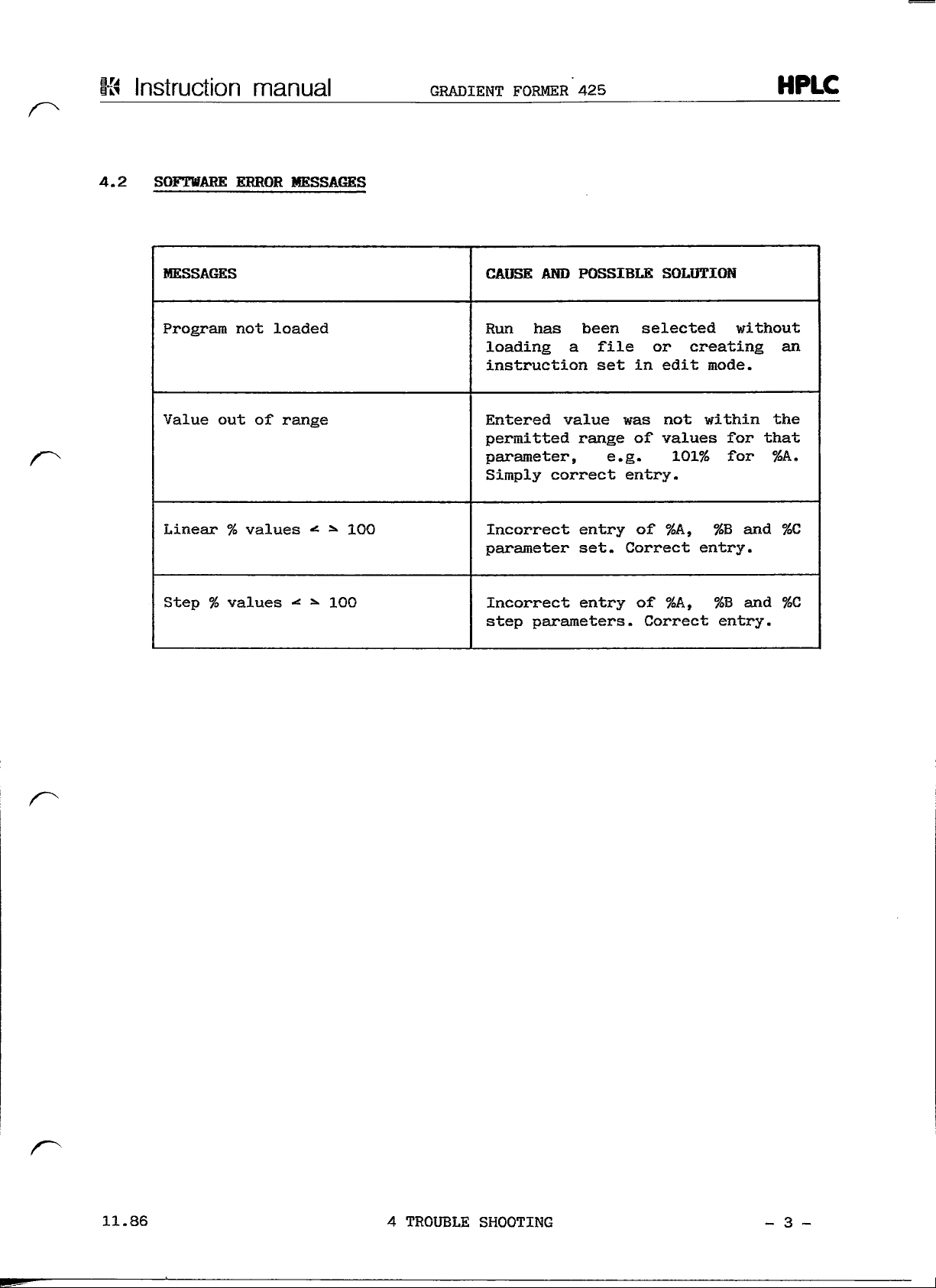
4.2
SOFTWARE
manual
EREOR
MESSAGES
GRADIENT
FORMER
425
HPLC
MESSAGES
Program
Value
Linear % values
Step % values
not
out of
loaded
ränge
•*• •*•
*•
*>
100
100
CAUSE
Run
AND
has
POSSIBLE
been
loading a file
instruction
Entered
permitted
Parameter,
Simply
Incorrect
Parameter
set in
value
was not
ränge
e.g.
correct entry.
entry
set.
Incorrect entry
step
parameters.
SOLÜTION
selected
or
edit
without
creating
mode.
within
of
values
101%
of
%A,
for
for
%B
and
Correct entry.
of
%A,
%B
and
Correct entry.
an
the
that
%A„
%C
%C
»•
11.86
4
TROUBLE
SHOOTING
- 3 -

13
Instruction
manual
GRADIENT
FORMER
425
HPLC
TABLE
5.
5.1
OF
CONTENTS
MAINTENANCE
Routine
5.2
Spare
parts
maintenance
3
2
page
11
„86
5
MAINENTANCE
- l -
4
Instruction
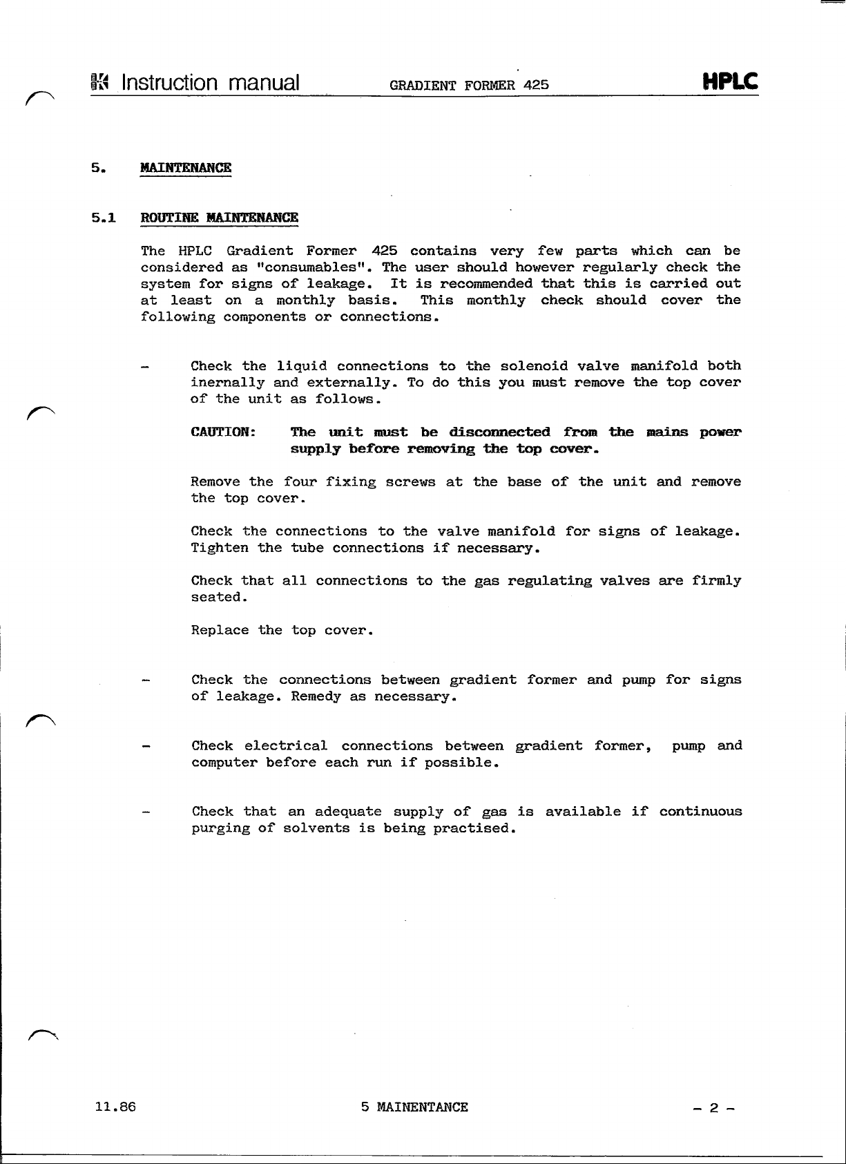
MAINTENANCE
5.1
ROUTINE
The
HPLC Gradient Former
considered
system
at
least
following
-
Check
manual
MAINTENANCE
äs
"consumables".
for
signs
on a monthly
components
inernally
of the
the
unit
of
liquid
and
GRADIENT FORMER
425
contains very
The
user
should
leakage.
or
connections
externally.
äs
follows.
It
is
recommended
basis. This
connections.
to the
To do
monthly
this
425
HPLC
few
parts
however
that
regulärly
this
which
is
check should cover
solenoid
you
must
valve
remove
manifold both
can
check
carried
the top
be
the
out
the
cover
CAÜTION:
Remove
the
Check
the
top
the
Tighten
Check
that
seated.
Replace
Check
the
of
leakage.
Check
electrical connections between gradient former,
Computer
Check
that
purging
The
unit
supply
befbre
four fixing
cover.
connections
the
tube connections
all
connections
the top
cover.
connections
Remedy
before
an
of
solvents
äs
each
adequate supply
nnist
be
removing
screws
to the
disconnected
at the
valve manifold
if
necessary.
to the gas
between
gradient
necessary.
run if
possible.
of gas is
is
being practised.
the top
base
regulating
former
from
cover.
of the
for
the raains
unit
signs
valves
and
available
and
of
are
pump
for
pump
if
continuous
power
remove
leakage.
firmly
signs
and
11.86
5
MAINENTANCE
- 2 -

Kä
Instruction manual
5.2
SPARE
PARTS
The
following
spare
representative.
Part
Number
parts
Please
always
Description
can
quote
GRADIENT
be
ordered
the
FORMER
425
through
corresponding
your
part
local
number.
HPLC
KONTRON
91-00560
71-00921
93-00667
93-00668
93-00665
96-00200
94-00983
07-89023
92-00627
87-00794
Outlet
Inlet
Gable,
Gable,
Solenoid
Gas
Gradient Controller printed circuit
Tubing
Inlet
Solvent
tube
connection
valve
purge
for gas
filter
for
Pump
gradient
gradient former - pump
valve
valve
former - Computer
assy
assy,
purge
420
coniplete
feed tube
(GF425 - PÜ420)
faoard
07.90
5
MAINENTANCE
- 3 -
 Loading...