

Page 1
KTLX800/pITX
KTD-S0023-A
Page 2

User Information
Table of Contents
» Table of Contents «
1 User Information .............................................................................1
1.1 About This Document.................................................................................................... 1
1.2 Copyright Notice.......................................................................................................... 1
1.3 Trademarks................................................................................................................. 1
1.4 Standards................................................................................................................... 1
1.5 Warranty .................................................................................................................... 1
1.6 Life Support Policy ....................................................................................................... 2
1.7 Technical Support ........................................................................................................ 2
2 BIOS Update ...................................................................................3
2.1 Known Restrictions ...................................................................................................... 3
3 Graphics Interface............................................................................4
3.1 LCD/LVDS Technology Overview ...................................................................................... 4
3.1.1 Detailed Timing Descriptor (EDID or DisplayIDTM) ............................................................................. 4
3.1.2 24 Bit Color Mapping Tips............................................................................................................6
3.2 EDID 1.3 Specification (VESA) ........................................................................................ 7
3.3 DisplayIDTM Specification (VESA) ..................................................................................... 7
3.3.1 DisplayIDTM Parameter Summary ...................................................................................................7
3.3.2 DisplayIDTM Restrictions ..............................................................................................................8
3.3.3 LCD Panel Selection ................................................................................................................... 8
3.3.4 DisplayID
3.3.5 Building DisplayIDTM File ........................................................................................................... 10
3.3.6 Erasing DisplayIDTM Record ........................................................................................................ 10
3.3.7 EEPROM Update Tool ................................................................................................................ 10
TM
Windows
®
Tool .......................................................................................................... 9
4 SDIO/microSD Card Interface............................................................ 11
4.1 DOS Boot...................................................................................................................11
4.2 Windows® XP Boot.......................................................................................................11
4.3 Windows® XP Embedded Boot ........................................................................................11
5 CPLD Interface............................................................................... 12
5.1 Special Hints..............................................................................................................13
5.1.1 Reserved Bits.......................................................................................................................... 13
5.1.2 GPIO Input Register ................................................................................................................. 13
5.2 Programming Examples................................................................................................14
5.2.1 Watchdog Example................................................................................................................... 14
5.2.2 Digital I/O Example.................................................................................................................. 15
5.2.3 Fan Control Example ................................................................................................................ 16
KTLX800/pITX Software Guide
Page 3

User Information
Table of Contents
6 ACPI Thermal Management............................................................... 17
6.1 Active Cooling ............................................................................................................17
6.2 Temperature Limits .....................................................................................................17
6.3 Temperature Identifier.................................................................................................17
7 ACPI Wakeup ................................................................................. 18
7.1 Wake On LAN..............................................................................................................18
7.1.1 Windows® XP .......................................................................................................................... 18
7.1.2 Linux (Debian distributions)...................................................................................................... 18
8 JIDA32 Interface............................................................................ 19
8.1 Generic Part...............................................................................................................19
8.2 Display Part ...............................................................................................................19
8.3 I2C-Bus Part ..............................................................................................................19
8.3.1 Bus Number 0 (JIDA/Generic) .................................................................................................... 20
8.4 CPU Performance Part ..................................................................................................20
8.5 Hardware Monitor Part.................................................................................................20
8.5.1 Temperature........................................................................................................................... 20
8.6 Digital I/O Part...........................................................................................................21
8.7 Watchdog Part............................................................................................................21
8.8 JIDA32 Windows® Programming.....................................................................................22
8.8.1 Program Language C ................................................................................................................ 22
8.8.2 Program Language DELPHI ........................................................................................................ 23
8.8.3 Program Language VISUAL BASIC (VB.NET)................................................................................... 26
8.8.4 Module Definition File .............................................................................................................. 28
8.9 JIDA32 Linux Programming...........................................................................................30
9 Linux Support ............................................................................... 32
Appendix A: Reference Documents .............................................................. 33
Appendix B: Document Revision History .......................................................34
KTLX800/pITX Software Guide
Page 4

KTD-S0023-A Page 1 User Information
1 User Information
1.1 About This Document
This document provides information about products from KONTRON Technology A/S and/or its subsidiaries.
No warranty of suitability, purpose or fitness is implied. While every attempt has been made to ensure that
the information in this document is accurate the information contained within is supplied “as-is” - no
liability is taken for any inaccuracies. Manual is subject to change without prior notice.
KONTRON assumes no responsibility for the circuits, descriptions and tables indicated as far as patents or
other rights of third parties are concerned.
1.2 Copyright Notice
Copyright © 2010-2011, KONTRON Technology A/S, ALL RIGHTS RESERVED.
No part of this document may be reproduced or transmitted in any form or by any means, electronically or
mechanically, for any purpose without the express written permission of KONTRON Technology A/S.
1.3 Trademarks
Brand and product names are trademarks or registered trademarks of their respective owners.
1.4 Standards
KONTRON Technology A/S is certified to ISO 9000 standards.
1.5 Warranty
This product is warranted against defects in material and workmanship for the warranty period from the
date of shipment. During the warranty period KONTRON Technology A/S will at its discretion decide to
repair or replace defective products.
Within the warranty period the repair of products is free of charge as long as warranty conditions are
observed.
The warranty does not apply to defects resulting from improper or inadequate maintenance or handling by
the buyer, unauthorized modification or misuse, operation outside of the product’s environmental specifications or improper installation or maintenance.
KONTRON Technology A/S will not be responsible for any defects or damages to third party products that
are caused by a faulty KONTRON Technology A/S product.
KTLX800/pITX Software Guide
Page 5

KTD-S0023-A Page 2 User Information
1.6 Life Support Policy
KONTRON Technology's products are not for use as critical components in life support devices or systems
without express written approval of the general manager of KONTRON Technology A/S.
As used herein:
Life support devices or systems are devices or systems which
a) are intended for surgical implant into body or
b) support or sustain life and whose failure to perform, when properly used in accordance with instructions
for use provided in the labelling, can be reasonably expected to result in significant injury to the user.
A critical component is any component of a life support device or system whose failure to perform can be
reasonably expected to cause the failure of the life support device or system or to affect its safety or
effectiveness.
1.7 Technical Support
Please consult our web site at http://www.kontron.com/support for the latest product documentation,
utilities, drivers and support contacts
or use the special e-mail address sbc-support@kontron.com for a
technical problem. In any case you can always contact your board supplier for technical support.
Before contacting support please be prepared to provide as much information as possible:
Board identification:
Ë
Ë
Ë
Board configuration:
Ë
Ë
Ë
System environment:
Ë
Ë
Ë
Type
Part number (find PN on label)
Serial number (find SN on label)
DRAM type and size
BIOS revision (find in the BIOS Setup)
BIOS settings different than default settings (refer to the BIOS Setup section)
O/S type and version
Driver origin and version
Attached hardware (drives, USB devices, LCD panels ...)
KTLX800/pITX Software Guide
Page 6

KTD-S0023-A Page 3 BIOS Update
2 BIOS Update
The KONTRON update tool (based on the AMD utility 'FlashROM.com') is only available for the DOS operating system. First copy the files IPLXUPD.EXE, UPDATE.EXT (absolutely essential) and the BIOS file to a
directory. Only the following combination of command line arguments has been tested and should be used
for the update process.
COMMAND.COM must reside in the same directory or alternatively there has to be a valid path in the
Note:
variable COMSPEC.
The syntax of the DOS update tool is:
IPLXUPD /C /R <BIOS filename>
/C = destroy CMOS checksum
/R = warmstart after programming
Following combinations are valid:
IPLXUPD <BIOS filename>
IPLXUPD /C <BIOS filename>
IPLXUPD /C /R <BIOS filename>
2.1 Known Restrictions
When a USB drive (e.g. a key) is used for the Bios update it is recommended to switch off the power supply
after the update process. Reason: after a warmstart sometimes the Bios does not detect USB drives.
KTLX800/pITX Software Guide
Page 7

KTD-S0023-A Page 4 Graphics Interface
3 Graphics Interface
3.1 LCD/LVDS Technology Overview
3.1.1 Detailed Timing Descriptor (EDID or DisplayIDTM)
The input fields Pixel Clock, Horizontal Active, Horizontal Blank, Horizontal Sync Offset, Horizontal Sync
Width, Vertical Active, Vertical Blank, Vertical Sync Offset and Vertical Sync Width must be filled in with the
correct values according to the panel’s data sheet. In many cases the value for Horizontal/Vertical Blank
cannot be read directly from the data sheet. Instead terms such as Display Period (active pixels/lines) or
Horizontal/Vertical Total appear.
In this case the following calculation can be made:
⇒ Blank Value = Total Value – Active Value.
Sometimes the datasheet does not specify Sync Offset and/or Sync Width. In this case the permissible
values can only be determined though testing. However the rule is:
⇒ The sum of Sync Offset and Sync Width must not exceed the value for Horizontal/Vertical Blank.
Also datasheets are often different for displays with double pixel clock. If Pixel Clock and Horizontal Values
seem to be halved this must be corrected for input:
⇒ The values must always be entered as though it were a panel with single pixel clock.
Example 1:
PRIMEVIEW PM070WL4 (single pixel clock)
Data sheet specifications:
Clock Frequency [typ.] 32 MHz
HSync Period [typ.] 1056 Clocks (equivalent to Horizontal Total)
HSync Display Period [typ.] 800 Clocks (equivalent to Horizontal Active)
HSync Pulse Width [typ.] 128 Clocks
HSync Front Porch [typ.] 42 Clocks
HSync Back Porch [typ.] 86 Clocks
VSync Period [typ.] 525 Lines (equivalent to Vertical Total)
VSync Display Period 480 Lines (equivalent to Vertical Active)
VSync Pulse Width [typ.] 2 Lines
VSync Front Porch [typ.] 10 Lines
VSync Back Porch [typ.] 33 Lines
Result:
Pixel Clock 32
Horizontal Active 800
Horizontal Blank 256 ((128 + 42 + 86) → H. Pulse Width + H. Front Porch + H.
Back Porch)
Horizontal Sync Offset 42 (H. Front Porch)
Horizontal Sync Width 128 (H. Pulse Width)
Vertical Active 480
Vertical Blank 45 ((2 + 10 + 33) → V. Pulse Width + V. Front Porch + V. Back
Porch)
Vertical Sync Offset 10 (V. Front Porch)
Vertical Sync Width 3 (V. Pulse Width)
KTLX800/pITX Software Guide
Page 8
KTD-S0023-A Page 5 Graphics Interface
Example 2 (not useable on KTLX800/pITX):
SHARP LQ190E1LW01 (double pixel clock)
Data sheet specifications (no definition of Sync Offset and Sync Width):
Clock Frequency [typ.] 54 MHz
Horizontal Period (1) [typ.] 844 Clocks (equivalent to Horizontal Total)
Horizontal Display Period 640 Clocks (equivalent to Horizontal Active)
Vertical Period [typ.] 1066 Lines (equivalent to Vertical Total)
Vertical Display Period 1024 Lines (equivalent to Vertical Active)
Result:
Pixel Clock 108 (2 x 54 MHz)
Horizontal Active 1280 (2 x 640 Clocks)
Horizontal Blank 408 ((844 – 640) x 2 Clocks)
Horizontal Sync Offset 45 (normally approx. 10 – 15 % of Horizontal Blank)
Horizontal Sync Width 140 (normally approx. 30 – 70 % of Horizontal Blank)
Vertical Active 1024
Vertical Blank 42 (1066 – 1024 Lines)
Vertical Sync Offset 1 (normally approx. 1 – 3 Lines)
Vertical Sync Width 3 (normally approx. 1 – 15 Lines)
Example 3 (not useable on KTLX800/pITX):
LG-PHILIPS LM170E01-TLA1 (double pixel clock)
Data sheet specifications:
Clock Frequency [typ.] 54 MHz
Hsync Period [typ.] 844 Clocks
Horiz. Valid [typ.] 640 Clocks
Horiz. Back Porch [typ.] 124 Clocks
Horiz. Front Porch [typ.] 24 Clocks
Vsync Period [typ.] 1066 Lines
Vert. Valid [typ.] 1024 Lines
Vert. Back Porch [typ.] 38 Lines
Vert. Front Porch [typ.] 1 Line
Result:
Pixel Clock 108 (2 x 54 MHz)
Horizontal Active 1280 (2 x 640 Clocks → Horizontal Addr. Time)
Horizontal Blank 408 ((844 – 640) x 2 Clocks)
Horizontal Sync Offset 48 (2 x 24 Clocks → Horizontal Front Porch)
Horizontal Sync Width 112 (((408/2 – 124 – 24) x 2) → H. Blank – H. Back Porch – H.
Front Porch)
Vertical Active 1024 (Vertical Addr. Time)
Vertical Blank 42 (1066 – 1024 Lines)
Vertical Sync Offset 1 (Vertical Front Porch)
Vertical Sync Width 3 (Vertical Blank – Vertical Back Porch – Vertical Front Porch)
The following picture shows the typical video timing.
Timing Parameter Definitions
Blanking
Active Part
Blanking
H-/V-Video
Front
Porch
H-/V-Sync
Sync
Pulse
Width
pos.
Sync
neg.
Sync
Back
Porch
Address Time
Total
KTLX800/pITX Software Guide
Front
Porch
Sync
Pulse
Width
pos.
Sync
neg.
Sync
Back
Porch
Page 9
KTD-S0023-A Page 6 Graphics Interface
ace
3.1.2 24 Bit Color Mapping Tips 3.1.2 24 Bit Color Mapping Tips
The double pixel clock or 24-bit color depth can generally be taken from the datasheet. There are two
The double pixel clock or 24-bit color depth can generally be taken from the datasheet. There are two
interface modes existing at 24-bit color depth: FPDI (F
interface modes existing at 24-bit color depth: FPDI (F
I
nterface). Some panels use the line SELL LVDS (SELect Lvds data order). The LVDS data assignment in the
lat Panel Display Interface) or LDI (LVDS Display
datasheet can give you an indication by the last channel (e.g. RX3/TX3 – SELL LVDS = low) wether it is a LDI
panel (contains the lowest bits). Most panels have a FPDI interface.
Example:
FPDI data assignment (LVDS channel 3 even or odd):
Tx/Rx27 Red 6 (e.g. even: RE6 or ER6)
Tx/Rx5 Red 7
Tx/Rx10 Green 6 (e.g. even: GE6 or EG6)
Tx/Rx11 Green 7
Tx/Rx16 Blue 6 (e.g. even: BE6 or EB6)
Tx/Rx17 Blue 7
Tx/Rx23 not used
LDI data assignment (LVDS channel 3 even or odd):
Tx/Rx27 Red 0 (e.g. even: RE0 or ER0)
Tx/Rx5 Red 1
Tx/Rx10 Green 0 (e.g. even: GE0 or EG0)
Tx/Rx11 Green 1
Tx/Rx16 Blue 0 (e.g. even: BE0 or EB0)
Tx/Rx17 Blue 1
Tx/Rx23 not used
TxClk
TxOut0
G0
R5
R4
R3
R2 R1
R0
FPDI
TxOut1
TxOut2
B1
DE
B0
VS
G5 G4 G3 G2 G1
HS
B5
B4
B3
B2
TxOut3
B7
B6
G7 G6 R7
R6
t
cycle
LDI
TxClk
TxOut0
TxOut1
G2 R7 R6 R5
B3
R4
R3
R2
G3G4G5G6G7B2
TxOut2
TxOut3
DE VS HS B7 B6 B5
B1
B0 G1 G0
R1
B4
R0
KTLX800/pITX Software Guide
KTLX800/pITX Software Guide
Page 10
KTD-S0023-A Page 7 Graphics Interface
3.2 EDID 1.3 Specification (VESA)
The EDID (Extended Display Identification Data) record has a fixed structure. The first 8 bytes contain the
distinctive identification 00h, FFh, FFh, FFh, FFh, FFh, FFh, 00h. The end of the record is marked by the
checksum (1 byte). The result of the addition of all bytes including the checksum has to be zero.
For a comprehensive support of the majority of available panels you don't need all fields of the EDID
record. The Detailed Timing Descriptor (18 bytes) is the most important field. No 24bit panels (FPDI/LDI)
are supported though. This means EDID should only be used for 18bit panels.
For further information please consult the official EDID specification from the VESA comitee which has to be
payed.
3.3 DisplayID
TM
Specification (VESA)
Intended as a replacement for all previous EDID versions DisplayIDTM contains many new features. It's a
structure with several well defined elements (tags). Not every element that is listed in the specification has
to be part of the resulting data set (basic section).
KONTRON has decided to use this selection of tags (mandatory presence).
Tag Description
00h Product Identification Data Block (Vendor ID, Product Code, Manufacturing Date ...)
03h Type I Detailed Timing Data Block (Pixel Clock, Horizontal/Vertical Data ...)
0Ch Display Device Data Block (Device Technology, Operating Mode, Color Depth ...)
0Dh Interface Power Sequencing Data Block (Power On/Off Timing)
0Fh Display Interface Data Block (Interface Type, Interface Attribute ...)
3.3.1 DisplayIDTM Parameter Summary
Only a part of the parameters used in the DisplayIDTM Windows® tool are interpreted by a specific board. The
following table shows a summary of the used parameters (valid for KTLX800/pITX).
Group Parameter Comment
Type I Timing Pixel Clock
Type I Timing Horizontal Active
Type I Timing Horizontal Blank
Type I Timing Horizontal Sync Offset Front porch
Type I Timing Horizontal Sync Width
Type I Timing Vertical Active
Type I Timing Vertical Blank
Type I Timing Vertical Sync Offset Front porch
Type I Timing Vertical Sync Width
Display Interface 1 Bits per Pixel Color depth (18 or 24bit)
Display Interface 1 24 Bit Color Mapping
Display Interface 2 Signal Polarity Only H-Sync and V-Sync
Display Interface 2 DE Mode Only Normal mode + Fixed mode low
KTLX800/pITX Software Guide
Page 11
KTD-S0023-A Page 8 Graphics Interface
3.3.2 DisplayIDTM Restrictions
Depending on the graphic controller not all features can be used. The following table shows the most important restrictions.
Restrictions for KTLX800/pITX
Panels with dual or quad clock not supported (2 or 4 Pixel per Clock)
Many displays center the picture automatically using the DE-signal. In general the picture is centered
automatically in horizontal direction but some displays also center the picture vertically using this signal.
Only for displays that can be driven with a
these information please check the datasheet. With the KTLX800/pITX board the parameters for the typical
detailled timing out of the datasheet might not be correct for centering the picture. In general the exact
positioning of the picture has to be obtained experimental.
Variable power sequencing not supported
fixed mode timing a displacement of the picture is possible. For
3.3.3 LCD Panel Selection
The choice of an LCD display is basically defined by two parameters.
Parameter Value
Pixel per Clock (Channels) 1
Pixel Clock Range 20 MHz - 135 MHz
Currently this leads to a maximum resolution of
With the AMD graphic driver it is not guaranteed that every resolution can be achieved. KONTRON does not
guarantee the correct function of the board for untypical resolution. In principal the use of DisplayID
allows realizing every special display resolution. For this a valid DisplayID
onboard EEPROM. Additionally the BIOS Setup entry
Advanced Settings/Display Configuration/Flat Panel Type
must be set to Auto.
Many displays with a resolution up to XGA (1024 x 768) have a digital (TTL) interface. KONTRON offers a
special adapter to connect these displays to the LVDS interface (KAB-ADAPT-LVDStoTTL with part number
61029).
1024 Pixel
TM
dataset must be written to the
TM
KTLX800/pITX Software Guide
Page 12
KTD-S0023-A Page 9 Graphics Interface
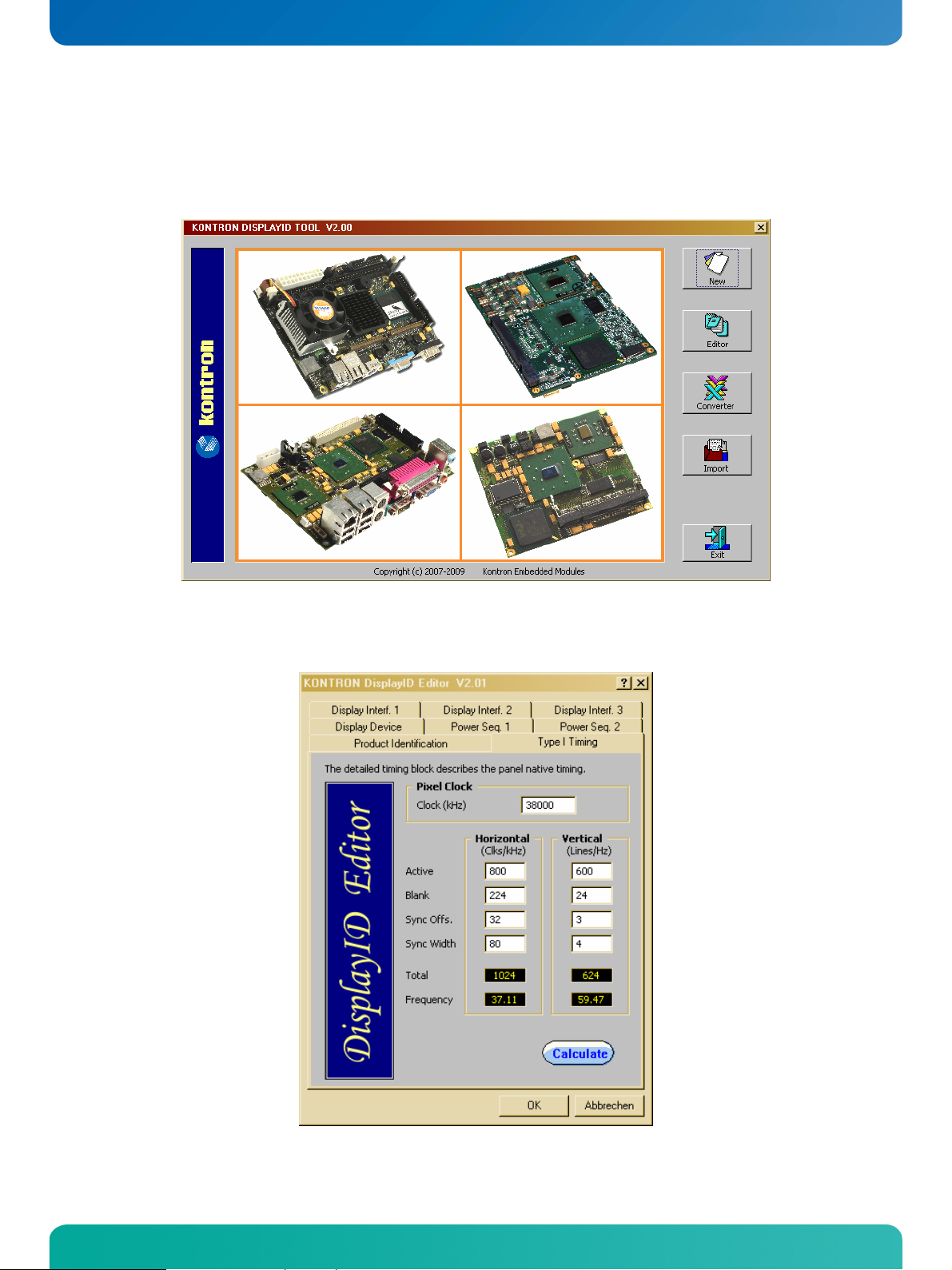
3.3.4 DisplayIDTM Windows® Tool
The DisplayIDTM parameter can be modified with the DisplayIDTM Windows® tool.
For an example the following picture shows the input fields for the Detailed Timing parameters.
For more information see the documentation of the DisplayID
kontron.com).
KTLX800/pITX Software Guide
TM
tool (software can be downloaded from
Page 13

KTD-S0023-A Page 10 Graphics Interface
The DisplayIDTM Editor saves the parameters in a intermediate file format. The file extension is 'KDD' (Kon-
isplayIDTM Data). This file format cannot be used to program the onboard EEPROM.
tron D
For transfering this file format into the binary file format for the EEPROM apply the Converter.
3.3.5 Building DisplayIDTM File
Start the Windows® tool DisplayID.exe.
Use the Editor if you want to modify an existing DisplayIDTM file or select New to create a
complete new record.
Change respectively enter new parameters.
Save the parameters in a file with the extension 'KDD'.
Open the saved 'KDD'-file using the Converter.
Save the binary file with the extension 'KDB' (Kontron DisplayIDTM Binary).
Program the onboard EEPROM using the board specific DOS update tool.
3.3.6 Erasing DisplayIDTM Record
Programming the first 128 bytes in the EEPROM with the values 00h or FFh deletes a valid DisplayIDTM
record.
3.3.7 EEPROM Update Tool
The syntax of the DOS EEPROM update tool is:
IPLX-DID <option> <filename>
/W = read a file (must be KDB-format) and write the content to the EEPROM
/R = read the EEPROM and write the content to a file
/C = read a file and compare the content with the EEPROM
/D = clear the EEPROM content (without filename)
KTLX800/pITX Software Guide
Page 14

KTD-S0023-A Page 11 SDIO/microSD Card Interface
4 SDIO/microSD Card Interface
The following operating systems allow booting from a microSD card: DOS, Linux and Windows® XP Embedded.
Attention
4.1 DOS Boot
All standard DOS programs for partitioning and formatting can be used (e.g. FDISK.EXE and FORMAT.COM).
However it can not be guaranteed that all functions of INT13h respectively INT21h work correctly.
Condition
The table shows a list of the tested DOS versions.
: only the microSD card interface is bootable - not the second SDIO pin header.
: the microSD card is formatted as a harddisk.
Operating System Version Result
MS-DOS 6.22
MS-DOS WIN 98 (7.10)
DR-DOS 7.03
4.2 Windows
®
XP Boot
Direct installation of Windows® XP on a microSD card is not possible at the moment.
4.3 Windows
®
XP Embedded Boot
As the microSD interface of the KTLX800/pITX is an USB/SDIO bridge it is no problem to boot this operating
system from the microSD card. Only the standard USB boot packages are needed.
KTLX800/pITX Software Guide
Page 15

KTD-S0023-A Page 12 CPLD Interface
5 CPLD Interface
Various functions are implemented in two CPLDs: e.g. watchdog, digital I/O and fan control. Access to the
CPLD register is via an index-data register pair using only two I/O byte locations (fixed addresses).
Index Register Data Register
Register overview:
Index Type Reset Function
0x00 RO --- CPLD version register
0x02 RW
0x03 RO ---
0x04 RW
0x05 RW
0x06 RW
0x07 RO ---
0x08 RW
0xA80 0xA81
System control register
Bit 0 + 7 Reserved
Bit 1 Autostart function
0 = do nothing
1 = restart
Bit 2 Enable/disable LAN controller
0 = disabled
1 = enabled
Bit 3 Enable/disable COM1/2 interf.
0 = disabled
1)
0x7C
1 = enabled
Bit 4 Enable/disable GPIO CPLD
0 = disabled
1 = enabled
Bit 5 Enable/disable onboard flash
0 = disabled
1 = enabled
Bit 6 Enable/disable SDIO/4th USB
0 = disabled
1 = enabled
System status register
Bit 0 Crisis jumper
0 = active
1 = not active
Bit 1 Autostart jumper
0 = active
1 = not active
Bit 2 Backlight polarity jumper
0 = inverted
1 = not inverted
Bit 3 - 7 Reserved
Reserved register
1)
0xCF
Bit 0 - 7 Reserved
Backlight register
1)
0x80
Bit 0 - 7 Brightness value
Fan speed control register
1)
0x08
Bit 0 - 3 Fan output value
Bit 4 - 7 Rotation speed divider
Fan rotation speed register
Bit 0 - 7 Fan rotation speed value
Watchdog control register
Bit 0 - 1 Watchdog time value
Bit 2 - 3 Reserved
Bit 4 Watchdog time base
0 = seconds
1 = minutes
1)
0x00
Bit 5 Reserved
Bit 6 Watchdog control
0 = disabled
1 = enabled
Bit 7 Trigger control
0 = disabled
1 = enabled
KTLX800/pITX Software Guide
Page 16

KTD-S0023-A Page 13 CPLD Interface
The GPIO registers represent an exception. The access is executed with linear addressing and 16 bit data
width (fixed addresses).
Register Range
Register overview:
Offset Type Reset Function
0x00 RO ---
0x02 RW
0x04 RW
0x06 RW
0x08 RW
0x0A RW
Note: 1) Default Setup settings.
0x0000
0x0000
0x0000
0x0000
0x0000
0xB00 - 0xB0B
GPIO data input register
Bit 0 = GPIO0 ... Bit 15 = GPIO15
0 = define low input
1 = define high input
GPIO data output register
Bit 0 = GPIO0 ... Bit 15 = GPIO15
1)
0 = define low output
1 = define high output
GPIO data direction register
Bit 0 = GPIO0 ... Bit 15 = GPIO15
1)
0 = define input
1 = define output
GPIO tri-state register
Bit 0 = GPIO0 ... Bit 15 = GPIO15
1)
0 = normal output
1 = tri-state output
GPIO interrupt polarity register
Bit 0 = GPIO0 ... Bit 15 = GPIO15
1)
0 = falling edge
1 = rising edge
GPIO interrupt register
Bit 0 = GPIO0 ... Bit 15 = GPIO15
1)
0 = interrupt disabled
1 = interrupt enabled
5.1 Special Hints
The following remarks must be considered (especically the first hint).
5.1.1 Reserved Bits
Every bit which is marked as Reserved may not be changed. Not observing this hint can in the worst case
lead to system crashes, e.g. after a warm boot.
5.1.2 GPIO Input Register
The input register reflects the status of the pins which are defined as output. Example: if GPIO7 defined as
an output the GPIO7 bit in the input register reads back low level when the output has low level and a high
level when the output has high level.
KTLX800/pITX Software Guide
Page 17

KTD-S0023-A Page 14 CPLD Interface
5.2 Programming Examples
The following examples (DOS programs) show the access to the CPLD features (C compiler: BORLAND C++).
These programs cannot be run on Linux and Windows®.
Note:
5.2.1 Watchdog Example
#include <stdio.h>
#include <dos.h>
#define CPLD_BASE_ADDR 0xA80
#define WDT_INDEX 0x08
#define WDT_ENABLE 0x40
#define WDT_TRIGGER 0x80
#define WDT_1SEC 0x00
#define WDT_5SEC 0x01
#define WDT_10SEC 0x02
#define WDT_30SEC 0x03
#define WDT_1MIN 0x10
#define WDT_5MIN 0x11
#define WDT_10MIN 0x12
void ActivateWatchdog (void)
{
outp (CPLD_BASE_ADDR, WDT_INDEX);
outp (CPLD_BASE_ADDR+1, WDT_10SEC);
delay (1); // wait one millisecond
outp (CPLD_BASE_ADDR+1, WDT_ENABLE);
}
void TriggerWatchdog (void)
{
outp (CPLD_BASE_ADDR, WDT_INDEX);
outp (CPLD_BASE_ADDR+1, WDT_TRIGGER | WDT_ENABLE);
delay (1); // wait one millisecond
outp (CPLD_BASE_ADDR+1, WDT_ENABLE);
}
void main (void)
{
int i;
ActivateWatchdog ();
for (i = 0; i < 5; i++) // wait half of expiry time (= 5 seconds)
delay (1000); // wait 1 second
TriggerWatchdog (); // trigger the watchdog - total expiry time now 15 seconds
}
KTLX800/pITX Software Guide
Page 18

KTD-S0023-A Page 15 CPLD Interface
5.2.2 Digital I/O Example
#include <stdio.h>
#include <dos.h>
#include <conio.h>
#define CPLD_BASE_ADDR 0xB00
#define GPIO_INPUT_OFFS 0x00
#define GPIO_OUTPUT_OFFS 0x02
#define GPIO_DIRECTION_OFFS 0x04
void RouteDigitalIO (unsigned int value)
{
outpw (CPLD_BASE_ADDR+GPIO_DIRECTION_OFFS, value);
}
void WriteDigitalIO (unsigned int value)
{
outpw (CPLD_BASE_ADDR+GPIO_OUTPUT_OFFS, value);
}
unsigned int ReadDigitalIO (void)
{
unsigned int value;
value = inpw (CPLD_BASE_ADDR+GPIO_INPUT_OFFS);
return value;
}
void main (void)
{
unsigned int val;
RouteDigitalIO (0xFFFF);
WriteDigitalIO (0xAA55);
val = ReadDigitalIO ();
printf ("\nInput value = %04X\n", val);
}
KTLX800/pITX Software Guide
Page 19

KTD-S0023-A Page 16 CPLD Interface
5.2.3 Fan Control Example
#include <stdio.h>
#include <dos.h>
#include <conio.h>
#define CPLD_BASE_ADDR 0xA80
#define FAN_CTRL_INDEX 0x06
#define FAN_MASK 0x0F
#define RESERVED_MASK 0xF0
void SetFanVal (unsigned char value)
{
unsigned char reg;
outp (CPLD_BASE_ADDR, FAN_CTRL_INDEX);
reg = inp (CPLD_BASE_ADDR+1);
reg &= RESERVED_MASK;
value &= FAN_MASK;
value |= reg;
outp (CPLD_BASE_ADDR+1, value);
}
void main (void)
{
SetFanVal (0x05);
getch ();
SetFanVal (0x0F);
}
KTLX800/pITX Software Guide
Page 20

KTD-S0023-A Page 17 ACPI Thermal Management
6 ACPI Thermal Management
The ACPI thermal management supports one mode: active cooling (no performance loss, but noise production).
6.1 Active Cooling
The operating system continuously polls the temperature using the ACPI method '_TZP' (Thermal Zone
olling). This is done automatically by Linux - for Windows® operating systems an additional tool is needed
P
®
as Windows
For example the tool
CPUID HWMonitor Vers. 1.14.0 or greater
can be used.
This approach accounts the total control of the fan through the temperature control and the fan can not be
switched seperatly on and off by the ACPI methods. This is only possible when inside the BIOS Setup the
setting Advanced/ACPI Configuration/ACPI Cooling Options/Active Trip Point is set to Disabled.
ignores the ACPI method '_TZP'.
6.2 Temperature Limits
Both trip points have the setting Disabled. This is not a real deactivating of the trip points but the corresponding value is set to 125°C which is the internal catastrophic temperature.
6.3 Temperature Identifier
Within operating systems (e.g. Linux) the temperature can be determined through the identifier THRM:
cat /proc/acpi/thermal_zone/THRM/temperature
KTLX800/pITX Software Guide
Page 21

KTD-S0023-A Page 18 ACPI Wakeup
7 ACPI Wakeup
One wake event is possible: Wake On LAN (WOL).
7.1 Wake On LAN
7.1.1 Windows® XP
The Intel® network driver does not support WOL.
7.1.2 Linux (Debian distributions)
Linux normally disables the wake functionality. This can be verified within the terminal with
cat /proc/acpi/wakeup
The following command allows the activation of a wake function (example USB0):
echo USB0 > /proc/acpi/wakeup
KTLX800/pITX Software Guide
Page 22

KTD-S0023-A Page 19 JIDA32 Interface
8 JIDA32 Interface
Most KONTRON single board computers (SBCs) are equipped with unique hardware features that cannot be
accessed with standard API. The JIDA32 interface allows you to access this features in a hardware independent manner under popular 32-bit operating systems.
Not mentioned parts of the JIDA32 interface are not supported and can lead to wrong results.
8.1 Generic Part
Each SBC has a unique seven letter name that corresponds directly with the physical type of board.
Examples are PLX8, PDOT, BQBA and B690. Boards are also divided into classes. The currently defined
classes are CPU, VGA and IO. Each board has one primary class but it can also have any number of
secondary classes. This allows you to talk to a class of boards that has a particular functionality without
knowing the exact name of the board.
Identifier Value
Board name IPLX
Primary class CPU
Secondary class VGA
Boot counter 0 ... 65535
Note: The boot counter is only incremented when a cold boot is performed. For a warm boot this value is not changed.
8.2 Display Part
In this part only the backlight control can be used. The contrast control is generally not supported (modern
graphic controllers don't anymore contain a STN LCD interface).
Identifier Value Comment
Backlight on/off Not supported
Backlight brightness 0 ... 255
Contrast on/off Not supported
Contrast value Not supported
End of dark boot Not supported
8.3 I2C-Bus Part
This part allows the access to serial busses. A write access is not allowed on every device though. KONTRON
does not guarantee the correct function of the component respectively the warranty claim is lost in case of
unallowed write cycles.
KTLX800/pITX Software Guide
Page 23
KTD-S0023-A Page 20 JIDA32 Interface
Bus Number Technology Type Device Count Comment
0 SMBus (primary) JIDA 3
8.3.1 Bus Number 0 (JIDA/Generic)
Through this bus several devices can be handled.
This bus allows access to the JIDA EEPROM in which KONTRON specific manufacturing parameters are
stored. A damage of these parameters leads to a loss of warranty. Due to this a write cycle may only be performed above a defined address.
Device Address Size Read Access Write Access
Temp. sensor 98h 256 Bytes Yes Yes
SPD EEPROM A0h 256 Bytes Yes No, forbidden
JIDA EEPROM A8h 512 Bytes Yes
Yes, between
28h to 1C8h
8.4 CPU Performance Part
This part implements power management functions.
Function Supported
CPU throttling No
CPU frequency No
8.5 Hardware Monitor Part
The hardware monitor part contains in most cases several subsections.
Section Sensor Count
Temperature 2
Fan Not supported
Voltage Not supported
8.5.1 Temperature
The term On-Chip diode designates the chip temperature of the temperature sensor (with no dependence to
the CPU temperature).
Sensor Number Abs. Thermal Limit
On-Chip diode 0 0 to +800 C
CPU diode 1 0 to +1000 C
KTLX800/pITX Software Guide
Page 24

KTD-S0023-A Page 21 JIDA32 Interface
8.6 Digital I/O Part
This part defines the availability of digital input/output lines.
Type Port Pin Count Position
Input or Output 0 8 Bit 0 - 7
Input or Output 1 8 Bit 0 - 7
Input/Output 2 - 7 Not supported
8.7 Watchdog Part
The watchdog can be programmed with discrete timeout values on boards with CPLD implementation or in
millisecond resolution with boards using a Super-I/O. In the discrete value scenario if there is no exact
match to the timeout value the next higher one is used (Example KTLX800/pITX: programmed value = 12
seconds, activated value = 30 seconds).
Type Steps Timeout Values Result
CPLD 7
1, 5, 10, 30 seconds
1, 5, 10 minutes
RESET
NMI not supported
KTLX800/pITX Software Guide
Page 25

KTD-S0023-A Page 22 JIDA32 Interface
8.8 JIDA32 Windows
®
Programming
For further information see the actual JIDA32 documentation (JIDA32.pdf).
8.8.1 Program Language C
The demo program reads and shows the board name and the first 16 bytes of SPD EEPROM (SMBus). The
program uses the static linked library JIDA.LIB.
Example:
#include <windows.h>
#include "jida.h"
#define I2C_BUS 1
#define DEV_ADDR 0xA0
INT WINAPI WinMain (HINSTANCE hInstance, HINSTANCE hPrevInstance, LPSTR lpCmdLine, INT nCmdShow)
{
BOOL bRet;
HJIDA hJida = (DWORD) NULL;
CHAR szStr1 [128],
szStr2 [32],
szVal [JIDA_BOARD_MAX_SIZE_ID_STRING];
UCHAR uVal [32];
if (JidaDllInitialize ())
{
if (JidaDllIsAvailable ())
{
if (JidaBoardOpen (JIDA_BOARD_CLASS_CPU, 0, JIDA_BOARDINFO_FLAGS_DEFAULT, &hJida))
{
bRet = JidaBoardGetName (hJida, (LPTSTR) szVal, JIDA_BOARD_MAX_SIZE_ID_STRING);
wsprintf (szStr1, "JidaBoardGetName = %d / %s", bRet, szVal);
lstrcpy (szStr2, "DEMO");
MessageBox (NULL, szStr1, szStr2, MB_OK | MB_ICONEXCLAMATION);
JidaI2CRead (hJida, I2C_BUS, DEV_ADDR, (LPBYTE) &uVal[0], 16);
wsprintf (szStr1, "JidaI2CRead = %02X %02X %02X %02X %02X %02X %02X %02X",
uVal[0], uVal [1], uVal[2], uVal [3],
uVal[4], uVal [5], uVal[6], uVal [7]);
MessageBox (NULL, szStr1, szStr2, MB_OK | MB_ICONEXCLAMATION);
JidaBoardClose (hJida);
}
}
JidaDllUninitialize ();
}
return (INT) FALSE;
}
KTLX800/pITX Software Guide
Page 26

KTD-S0023-A Page 23 JIDA32 Interface
8.8.2 Program Language DELPHI
The demo program activates the watchdog (timeout = 30 seconds). The keyword 'var' passes the argument
by reference.
Example:
unit mainU;
interface
uses
Windows, Messages, SysUtils, Variants, Classes, Graphics, Controls, Forms, Dialogs, StdCtrls;
type
HJIDA = LongInt;
type
TForm1 = class (TForm)
Button1: TButton;
procedure Button1Click (Sender: TObject);
private
{ Private-Deklarationen }
public
hJida: HJIDA;
{ Public-Deklarationen }
end;
function JidaDllInitialize : Boolean {$IFDEF WIN32} stdcall {$ENDIF}; external 'JIDA.DLL';
function JidaDllUninitialize : Boolean {$IFDEF WIN32} stdcall {$ENDIF}; external 'JIDA.DLL';
function JidaDllIsAvailable : Boolean {$IFDEF WIN32} stdcall {$ENDIF}; external 'JIDA.DLL';
function JidaBoardOpen (pszClass:PChar; dwNum:LongInt; dwFlags:LongInt; var phJida:HJIDA) : Boolean
{$IFDEF WIN32} stdcall {$ENDIF}; external 'JIDA.DLL';
function JidaWDogSetConfig (hJida:HJIDA; dwType:LongInt; dwTimeout:LongInt; dwDelay:LongInt;
dwMode:LongInt) : Boolean {$IFDEF WIN32} stdcall {$ENDIF}; external 'JIDA.DLL';
var
Form1: TForm1;
const
JIDA_BOARD_CLASS_CPU = 'CPU'#0;
JIDA_FLAGS_DEFAULT = 0;
JIDA_TIMEOUT_VALUE = 30000;
JIDA_DELAY_VALUE = 0; // Delay not supported
JIDA_REBOOT_MODE = 0; // NMI not supported
implementation
{$R *.dfm}
KTLX800/pITX Software Guide
Page 27

KTD-S0023-A Page 24 JIDA32 Interface
procedure TForm1.Button1Click(Sender: TObject);
begin
{Method 1}
if JidaDLLInitialize () then
begin
if JidaDllIsAvailable () then
begin
if JidaBoardOpen (JIDA_BOARD_CLASS_CPU, 0, JIDA_FLAGS_DEFAULT, hJida) then
JidaWDogSetConfig (hJida, 0, JIDA_TIMEOUT_VALUE, JIDA_DELAY_VALUE, JIDA_REBOOT_MODE);
end;
JidaDllUninitialize ();
end;
end;
end.
The associated DFM file:
object Form1: TForm1
Left = 196
Top = 107
Width = 367
Height = 390
Caption = 'KONTRON JIDA32 TEST'
Color = clBtnFace
Font.Charset = DEFAULT_CHARSET
Font.Color = clWindowText
Font.Height = -11
Font.Name = 'MS Sans Serif'
Font.Style = []
OldCreateOrder = False
PixelsPerInch = 96
TextHeight = 13
object Button1: TButton
Left = 104
Top = 128
Width = 75
Height = 25
Caption = 'Test JIDA32'
TabOrder = 0
OnClick = Button1Click
end
end
KTLX800/pITX Software Guide
Page 28

KTD-S0023-A Page 25 JIDA32 Interface
The associated DPR file:
program Jidatest;
uses
Forms,
mainU in 'mainU.pas' {Form1};
{$R *.res}
begin
Application.Initialize;
Application.CreateForm (TForm1, Form1);
Application.Run;
end.
KTLX800/pITX Software Guide
Page 29

KTD-S0023-A Page 26 JIDA32 Interface
8.8.3 Program Language VISUAL BASIC (VB.NET)
The demo program shows the board count value and activates the watchdog (timeout = 10 seconds).
Example:
Public Class JidaTest
Declare Auto Function JidaDllInitialize Lib "JIDA.DLL" () As Boolean
Declare Auto Function JidaDllUninitialize Lib "JIDA.DLL" () As Boolean
Declare Auto Function JidaDllIsAvailable Lib "JIDA.DLL" () As Boolean
Declare Auto Function JidaBoardCount Lib "JIDA.DLL" _
(ByVal classstr As String, ByVal flags As UInteger) As UInteger
Declare Auto Function JidaBoardOpen Lib "JIDA.DLL" _
(ByVal classstr As String, ByVal num As UInteger, ByVal flags As UInteger, _
ByRef handle As UInteger) As Boolean
Declare Auto Function JidaBoardClose Lib "JIDA.DLL" (ByVal handle As UInteger) As Boolean
Declare Auto Function JidaWDogSetConfig Lib "JIDA.DLL" (ByVal handle As UInteger, _
ByVal type As UInteger, ByVal timeout As UInteger, ByVal delay As UInteger, _
ByVal mode As UInteger) As Boolean
Public Sub Button1_Click(ByVal sender As System.Object, ByVal e As System.EventArgs) Handles Button1.Click
Const JIDA_BOARD_CLASS_CPU = "CPU"
Const JIDA_BOARD_OPEN_FLAGS_PRIMARYONLY = 1
Const JIDA_BOARDINFO_FLAGS_DEFAULT = 0
Const TIMEOUT_VALUE = 10000
Const DELAY_VALUE = 0 'Delay not supported
Const REBOOT_BOARD = 0 'NMI not supported
Dim handle As UInteger
If JidaDllInitialize() Then
If JidaDllIsAvailable() Then
If JidaBoardOpen(JIDA_BOARD_CLASS_CPU, 0, JIDA_BOARDINFO_FLAGS_DEFAULT, handle) Then
MsgBox("BoardCount = " & JidaBoardCount(JIDA_BOARD_CLASS_CPU, _
JIDA_BOARD_OPEN_FLAGS_PRIMARYONLY))
JidaWDogSetConfig(handle, 0, TIMEOUT_VALUE, DELAY_VALUE, REBOOT_BOARD)
JidaBoardClose(handle)
End If
End If
JidaDllUninitialize()
End If
End Sub
End Class
KTLX800/pITX Software Guide
Page 30

KTD-S0023-A Page 27 JIDA32 Interface
The associated Designer file:
<Global.Microsoft.VisualBasic.CompilerServices.DesignerGenerated()> Partial Class JidaTest
Inherits System.Windows.Forms.Form
<System.Diagnostics.DebuggerNonUserCode()> Protected Overrides Sub Dispose(ByVal disposing As Boolean)
Try
If disposing AndAlso components IsNot Nothing Then
components.Dispose()
End If
Finally
MyBase.Dispose(disposing)
End Try
End Sub
Private components As System.ComponentModel.IContainer
<System.Diagnostics.DebuggerStepThrough()> Private Sub InitializeComponent()
Me.Button1 = New System.Windows.Forms.Button
Me.SuspendLayout()
'
'Button1
'
Me.Button1.Location = New System.Drawing.Point(38, 39)
Me.Button1.Name = "Button1"
Me.Button1.Size = New System.Drawing.Size(75, 23)
Me.Button1.TabIndex = 0
Me.Button1.Text = "Run Test"
Me.Button1.UseVisualStyleBackColor = True
'
'JidaTest
'
Me.AutoScaleDimensions = New System.Drawing.SizeF(6.0!, 13.0!)
Me.AutoScaleMode = System.Windows.Forms.AutoScaleMode.Font
Me.ClientSize = New System.Drawing.Size(154, 96)
Me.Controls.Add(Me.Button1)
Me.Name = "JidaTest"
Me.Text = "JidaTest"
Me.ResumeLayout(False)
End Sub
Friend WithEvents Button1 As System.Windows.Forms.Button
End Class
KTLX800/pITX Software Guide
Page 31

KTD-S0023-A Page 28 JIDA32 Interface
8.8.4 Module Definition File
The calling program can refer to the function by name or by ordinal value. The tool IMPDEF.EXE (e.g.
BORLAND C++) make it possible to generate the DEF-file (from JIDA.DLL 06/07/2004, in newer DLLs the
ordinal value can be changed).
EXPORTS
JidaBoardClose @9
JidaBoardCount @6
JidaBoardCountA @50
JidaBoardCountW @55
JidaBoardGetBootCounter @12
JidaBoardGetBootErrorLog @75
JidaBoardGetInfo @11
JidaBoardGetInfoA @54
JidaBoardGetInfoW @59
JidaBoardGetName @10
JidaBoardGetNameA @53
JidaBoardGetNameW @58
JidaBoardGetOption @14
JidaBoardGetRunningTimeMeter @13
JidaBoardOpen @7
JidaBoardOpenA @51
JidaBoardOpenByName @8
JidaBoardOpenByNameA @52
JidaBoardOpenByNameW @57
JidaBoardOpenW @56
JidaBoardSetOption @15
JidaDllGetVersion @2
JidaDllInitialize @3
JidaDllInstall @40
JidaDllIsAvailable @5
JidaDllUninitialize @4
JidaFanCount @83
JidaFanGetCurrent @85
JidaFanGetInfo @84
JidaFanSetLimits @86
JidaI2CCount @29
JidaI2CIsAvailable @30
JidaI2CRead @31
JidaI2CReadRegister @33
JidaI2CType @63
JidaI2CWrite @32
JidaI2CWriteReadCombined @69
JidaI2CWriteRegister @34
JidaIOCount @35
JidaIOGetDirection @70
JidaIOGetDirectionCaps @72
JidaIOGetNameA @73
JidaIOGetNameW @74
KTLX800/pITX Software Guide
Page 32

KTD-S0023-A Page 29 JIDA32 Interface
JidaIOIsAvailable @36
JidaIORead @37
JidaIOSetDirection @71
JidaIOWrite @38
JidaIOXorAndXor @39
JidaJ32B @62
JidaJ32BTransAddr @68
JidaPerformanceGetCurrent @66
JidaPerformanceGetPolicy @77
JidaPerformanceGetPolicyCaps @76
JidaPerformanceSetCurrent @67
JidaPerformanceSetPolicy @78
JidaStorageAreaBlockSize @24
JidaStorageAreaCount @21
JidaStorageAreaErase @27
JidaStorageAreaEraseStatus @28
JidaStorageAreaRead @25
JidaStorageAreaSize @23
JidaStorageAreaType @22
JidaStorageAreaWrite @26
JidaTemperatureCount @79
JidaTemperatureGetCurrent @81
JidaTemperatureGetInfo @80
JidaTemperatureSetLimits @82
JidaVgaEndDarkBoot @20
JidaVgaGetBacklight @18
JidaVgaGetBacklightEnable @60
JidaVgaGetContrast @16
JidaVgaGetContrastEnable @64
JidaVgaSetBacklight @19
JidaVgaSetBacklightEnable @61
JidaVgaSetContrast @17
JidaVgaSetContrastEnable @65
JidaVoltageCount @87
JidaVoltageGetCurrent @89
JidaVoltageGetInfo @88
JidaVoltageSetLimits @90
JidaWDogCount @41
JidaWDogDisable @49
JidaWDogGetConfigStruct @46
JidaWDogGetTriggerCount @44
JidaWDogIsAvailable @42
JidaWDogSetConfig @48
JidaWDogSetConfigStruct @47
JidaWDogSetTriggerCount @45
JidaWDogTrigger @43
KTLX800/pITX Software Guide
Page 33
KTD-S0023-A Page 30 JIDA32 Interface
_
8.9 JIDA32 Linux Programming
Please note that the JIDA32 package does not include full sources. Instead precompiled objects are
provided that can be used to build a JIDA32 package for a certain environment (GCC, kernel, libc).
In order to handle GCC version incompatibilities and different kernel module build environments the
package includes different branches (you can use the GCC_3.x.x subdirectory for GCC 4.x.x compiler versions).
GCC_2.x.x
KERNEL_2.2.x_2.4.x
JIDA32R116_L114 JIDA_USER
GCC_3.x.x
KERNEL_2.2.x_2.4.x
KERNEL
2.6.x
Under each branch four subdirectories can be found:
JidaDrv: Includes the necessary source, library and build files to create the JIDA32 kernel driver
module (jida.ko for kernels 2.6.x, jida.o for kernels 2.2.x and 2.4.x).
JidaLib: Includes the necessary source, library and build files to create the JIDA32 interface
library (libjida.so, libjida.a).
JidaTst: Includes the necessary source and build files to create a simple JIDA32 test application
(jidatst).
JWdogTst: Includes the necessary source and build files to create a simple watchdog test appli-
cation (jwdogtst).
In order to build the JIDA32 kernel driver module (jida.ko/jida.o) you must install the complete kernel
sources for the destination kernel under /usr/src/linux or alternatively provide an environment variable
KERNELDIR that contains the path of the kernel sources.
After installation of the sources please configure, build and install the respective kernel and modules on
your system. Having done so please reboot and start the system using the new kernel.
In order to build the JIDA32 kernel driver, interface library and test applications go to the
./JIDAR116_L114/JIDA_USER/'GCC_VERSION'/'KERNEL_VERSION'
directory and enter 'make all'.
In order to automatically copy the created files to their destination directories please enter 'make install'
afterwards. This will copy the following files:
jida.ko to /lib/modules/$(KERNELRELEASE)/extra/ (for kernel 2.6.x)
or
jida.o to /lib/modules/$(KERNELRELEASE)/misc/ (for kernel 2.2.x/2.4.x)
libjida.so + libjida.a to /usr/lib/
jidatst + jwdogtst to /usr/bin/
jida.h + jwindefs.h to /usr/include/
KTLX800/pITX Software Guide
Page 34

KTD-S0023-A Page 31 JIDA32 Interface
You can provide a prefix for the above named directories with the INSTALL_MOD_PATH environment variable if you want to install the files into an alternative root file system. (Note:
After successfull build and installation you should run the sample application jidatst which will display the
following message:
JIDA system driver is incompatible or not installed.
Would you like to install it? (yes or no)
If you answer this question with 'yes' or 'y' the device node /dev/jida will be created and the driver
module loaded. Afterwards some basic JIDA32 test calls will be performed which display their results on the
screen. If you see this output the JIDA32 interface is operational.
If you have problems running JIDA please check if the device node /dev/jida is created with the correct
major/minor number and is accessible by the active user. Since version JIDAR115_L113 we are using
10/250 for device nodes if a kernel of the 2.6.x branch is used. JIDA drivers for older kernels or JIDA32
revisions use 99/0 for the device node.
kernel 2.6.x only)
Note: JIDA won't be detected automatically on kernel startup. You have to load it by yourself. You can either use the JidaDll-
Install function to do it or use "modprobe jida" before starting your application. Most Linux distributions provide other
possibilities to automatically load kernel modules. For Debian simply add a line with "jida" to the /etc/modules file.
Note: If you are using udev with a 2.6 kernel the device node will automatically be created. The default major/minor will be
10/250 which is reserved for local use. If this is conflicting with your own driver you can redefine the minor id to
something else by providing the minor=x parameter when loading the module. Example: modprobe jida minor=254.
KTLX800/pITX Software Guide
Page 35

KTD-S0023-A Page 32 Linux Support
9 Linux Support
Many Linux distributions have a problem with the graphic driver. The best choice is the usage of the VESA
framebuffer driver. The most unproblematic distribution is 'Knoppix' (based on 'Debian'). Use Knoppix
with the boot parameter 'fb????x????' (e.g. fb1024x768).
KTLX800/pITX Software Guide
Page 36

KTD-S0023-A Page 33 Appendix A: Reference Documents
Appendix A: Reference Documents
KONTRON Technology A/S can't guarantee the availability of internet addresses.
Document Internet Address
Advanced Configuration and Power Interface (ACPI) http://www.acpi.info/spec.htm
AT Attachment Storage Interface Specification (ATA) http://t13.org
Digital Visual Interface (DVI) http://www.ddwg.org
High Definition Audio Specification (HD Audio) http://www.intel.com/standards/hdaudio
High Speed Serialized AT Attachment (S-ATA) http://www.sata-io.org/developers
IEEE 802.3 Specification (Ethernet) http://standards.ieee.org/getieee802
Low Pin Count Interface Specification (LPC-Bus) http://developer.intel.com/design/chipsets/industry/lpc.htm
Open LVDS Display Interface Standard Spec. (Open LDI) http://www.national.com/analog/displays/open_ldi
PCI Express Base Specification (PCI Express) http://www.pcisig.com/specifications
SD Specification (SD Card) http://www.sdcard.org/developers/tech/sdio/sdio_spec
System Management Bus Specification (SMBus) http://www.smbus.org/specs
Universal Serial Bus Specification (USB) http://www.usb.org/developers/docs
KTLX800/pITX Software Guide
Page 37

KTD-S0023-A Page 34 Appendix B: Document Revision History
Appendix B: Document Revision History
Revision Date Author Changes
S0023-A 08/30/11 M. Hüttmann Added chapter 'BIOS Update Restrictions' and 'Linux Support'
S0023-0 05/12/11 M. Hüttmann Created preliminary manual
Corporate Offices
Europe, Middle East & Africa
Oskar-von-Miller-Str. 1
85386 Eching/Munich
Germany
Tel.: +49 (0)8165/ 77 777
Fax: +49 (0)8165/ 77 219
info@kontron.com
North America
14118 Stowe Drive
Poway, CA 92064-7147
USA
Tel.: +1 888 294 4558
Fax: +1 858 677 0898
info@us.kontron.com
KTLX800/pITX Software Guide
Asia Pacific
17 Building,Block #1,ABP
188 Southern West 4th Ring Road
Beijing 100070, P.R.China
Tel.: + 86 10 63751188
Fax: + 86 10 83682438
info@kontron.cn
 Loading...