

Page 1
ADD2-CRT
KTD-00735-C Public User Manual Date: 2009-05-18 Page 1 of 7
User Manual
for the Add-On card:
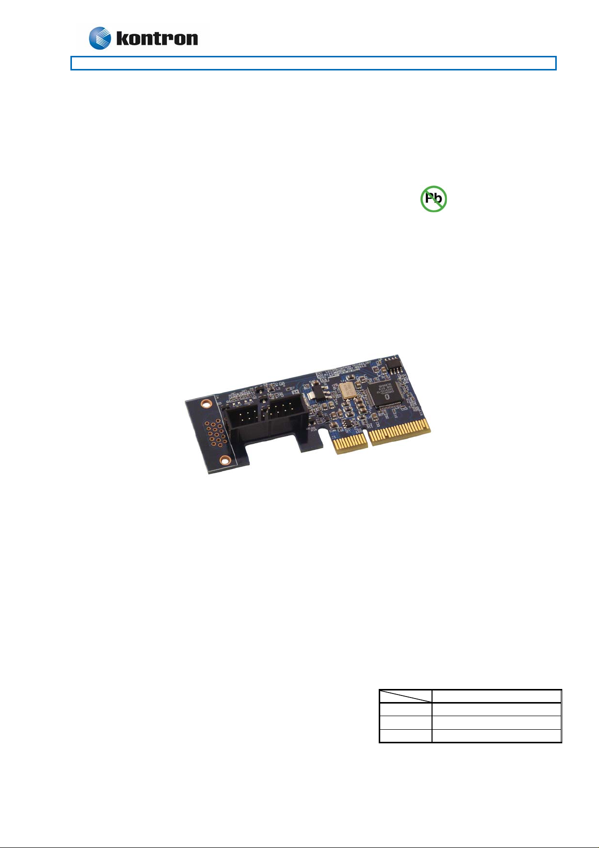
820954 ADD2-CRT
AGP Digital Display second generation card with Analogue RGB (CRT) output
Designed primarily for 986LCD-M family and KT965/Flex motherboards
820954 ADD2-CRT
ADD2-CRT
Part no. 820954
PCB no. 30103301
Ass. no. 68310000
Page 2
ADD2-CRT
KTD-00735-C Public User Manual Date: 2009-05-18 Page 2 of 7
Document revision history.
Revision Date By Comment
C May 18th 2009 MLA Text corrected on front page.
B Nov. 25th 2008 MLA BIOS version info added.
A Sep. 24th , 2007 MLA Minor corrections.
0 Sep. 17th , 2007 MLA Preliminary version.
Copyright Notice:
Copyright © 2007, KONTRON Technology A/S, ALL RIGHTS RESERVED.
No part of this document may be reproduced or transmitted in any form or by any means, electronically or
mechanically, for any purpose, without the express written permission of KONTRON Technology A/S.
Trademark Acknowledgement:
Brand and product names are trademarks or registered trademarks of their respective owners.
Disclaimer:
KONTRON Technology A/S reserves the right to make changes, without notice, to any product, including
circuits and/or software described or contained in this manual in order to improve design and/or performance.
Specifications listed in this manual are subject to change without notice. KONTRON Technology assumes no
responsibility or liability for the use of the described product(s), conveys no license or title under any patent,
copyright, or mask work rights to these products, and makes no representations or warranties that these
products are free from patent, copyright, or mask work right infringement, unless otherwise specified.
Applications that are described in this manual are for illustration purposes only. KONTRON Techn ology A/S
makes no representation or warranty that such application will be suitable for the specified use without
further testing or modification.
Page 3

ADD2-CRT
KTD-00735-C Public User Manual Date: 2009-05-18 Page 3 of 7
Life Support Policy
KONTRON Technology’s PRODUCTS ARE NOT FOR USE AS CRITICAL COMPONENTS IN LIFE
SUPPORT DEVICES OR SYSTEMS WITHOUT EXPRESS WRITTEN APPROVAL OF THE GENERAL
MANAGER OF KONTRON Technology A/S.
As used herein:
1. Life support devices or systems are devices or systems which, (a) are intended for surgical implant into
body, or (b) support or sustain life and whose failure to perform, when properly used in accordance with
instructions for use provided in the labeling, can be reasonably expected to result in significant injury to
the user.
2. A critical component is any component of a life support device or system whose failure to perform can be
reasonably expected to cause the failure of the life support device or system, or to affect its safety or
effectiveness.
KONTRON Technology Technical Support and Services
If you have questions about installing or using your KONTRON Technology Product, check this User’s
Manual first – you will find answers to most questions here. To obtain support, please contact your local
Distributor or Field Application Engineer (FAE).
Before Contacting Support: Please be prepared to provide as much information as possible:
ADD-On Board
1. Type.
2. Part-number (Number starting with “68”).
Configuration
1. Motherboard Type
2. BIOS Revision (Find the Version Info (BIOS ID) in the BIOS Setup Menu)
3. BIOS Settings different than Default Settings (Display related settings).
4. O/S Make and Version.
5. Graphic Driver Version numbers.
6. Attached Monitors etc.
Page 4

ADD2-CRT
KTD-00735-C Public User Manual Date: 2009-05-18 Page 4 of 7
Table of contents:
INTRODUCTION................................................................................................................................................5
MECHANICAL DRAWING.................................................................................................................................5
FUNCTIONAL DIAGRAM..................................................................................................................................6
CONNECTOR/CABLE KIT DESCRIPTIONS....................................................................................................6
INSTALLATION GUIDE.....................................................................................................................................7
ELECTRICAL SPECIFICATION........................................................................................................................7
Page 5

ADD2-CRT
KTD-00735-C Public User Manual Date: 2009-05-18 Page 5 of 7
Introduction
• Output Analogue RGB generated by three 10-bit video DAC’s
• Output to HDDB15 standard CRT RGB connector via pin-row connector and cable kit (821516)
• 821516 CRT Bracket cable is included
• PCB is prepared for optional onboard HDDB15 connector
• Input is SDVO via ADD2 interface (Intel multiplexed dual SDVO and PCIex16 interface)
• The SDVO is high-speed serial DVO (1G~2Gbps) at clock rates u p to 165Mpixels/s
• Complete Windows driver support
• Panel resolution up to 1600x1200 (frame rate 60 Hz)
• Monitor Detection supported through Hot Plug
The ADD2-CRT card is based on the Chrontel CH7317A Analogue RGB transmitter. The ADD2-CRT
supports resolutions up to 1600x1200 at 60 Hz frame rate. The card is designed for the PCI-Expressx16
connector which on the 986LCD-M family of motherboards and on the KT965/Flex motherboard is
multiplexed PCI-Expressx16 and SDVO. When the ADD2-DVI card is plugged into the PCI-Expressx16
connector then the motherboard automatically detects the card and select SDVO output.
Mechanical Drawing
The ADD2-CRT includes CRT Bracket cable (item no. 821516), see picture below.
CRT pin row J3
42.4
ADD2-CRT
Measures in mm
96.4
MB PCI-Expressx16
39.5
MB PCB
Page 6

ADD2-CRT
pply
)
A
KTD-00735-C Public User Manual Date: 2009-05-18 Page 6 of 7
Functional Diagram
DD2-CRT
VBIOS
I2C PROM
HDDB15 CRT connectorJ4(option
Pin-Row connector J3
SDVO to CRT
Converter #1
SDVO-B
PCI-Expressx16 connector
SDVO
5V Current limited
su
Motherboard with multiplexed PCI-Expressx16/SDVO connector
Note that VBIOS located in I2C is not used as default. The reason is that the BIOS used in the Kontron
Motherboards of 986LCD-M and KT965 families are supporting the ADD2-DVI card directly.
Connector/Cable kit descriptions
The 821516 CRT Bracket cable kit is 140mm long and is based on a pin socket connector (16 terminals) and
a HDDB15 standard VGA CRT connector. Optionally the ADD2-CRT card has a HDDB15 connector (J4)
having the same pinning as the cable kit HDDB15 connector.
821516 cable wiring:
Pin-Row J3 HDDB15 J4 and cable kit
Pin No. Pin No. Signal
1 11 NC
2 15 DDC Clock
3 10 GND
4 8 GND
5 14 Vsync
6 4 NC
7 9 +5V (55mA)
8 13 Hsync
9 3 Blue
10 7 GND
11 12 DDC Data
12 2 Green
13 6 GND
14 - NC
15 1 Red
16 5 GND
Page 7

ADD2-CRT
KTD-00735-C Public User Manual Date: 2009-05-18 Page 7 of 7
Installation Guide
Connect 821516 CRT Bracket cable to the ADD2-CRTcard
Plug in the ADD2-CRT card to the PCIe-x16 slot (nearest CPU)
Fix the ADD2-DVI card by bracket etc (not included)
Boot and enter BIOS
For the 986LCD-M BIOS 986LCD18 or above:
Select Chipset > North Bridge Configuration > Video Function Configuration >
Boot Type = [CRT+CRT2]
SDVO = [CRT]
For the KT965 BIOS KT965009 or above:
Select Chipset > North Bridge Configuration > Video Function Configuration >
Boot Type = [CRT+CRT2]
Select Exit menu.
Hint: Using also Secure CMOS = [Enabled] will make sure that Windows will not change Boot Type in BIOS.
Save Changes and Exit.
Boot into OS and load Intel Graphics Media Driver. For Windows install version 6.14.10.4859
(win2K_xp1431.exe) or newer.
Select output to Monitor 2 (or another configuration as requested).
Electrical Specification
Power consumption:
The +5V available on the CRT connector can deliver minimum 55mA continuously and 1A peak. The output
is protected by thermal shutdown circuit.
3.3V 0.8W max.
12V 0.5W max.
Operating temperature: 0-60ºC
 Loading...