

Page 1
KTAM3874/pITX
KTD-S0057-I
The pulse of innovation
Page 2

User Information
Table of Contents
» Table of Contents «
1 User Information .............................................................................1
1.1 About This Document.................................................................................................... 1
1.2 Copyright Notice.......................................................................................................... 1
1.3 Trademarks................................................................................................................. 1
1.4 Standards................................................................................................................... 1
1.5 Warranty .................................................................................................................... 1
1.6 Life Support Policy ....................................................................................................... 2
1.7 Technical Support ........................................................................................................ 2
2 U-Boot Setup ..................................................................................3
2.1 Setup Command .......................................................................................................... 3
2.2 Setup Usage................................................................................................................ 3
2.3 Display Menu .............................................................................................................. 4
2.3.1 Boot Display .............................................................................................................................4
2.3.2 Mirror Mode.............................................................................................................................. 4
2.3.3 LCD Panel Resolution.................................................................................................................. 5
2.3.4 LCD Panel Mapping ....................................................................................................................5
2.3.5 Backlight Output Control............................................................................................................. 5
2.3.6 Backlight Output Level ...............................................................................................................5
2.3.7 Backlight Brightness.................................................................................................................. 5
2.4 Devices Menu .............................................................................................................. 6
2.4.1 mPCI Express® Port .................................................................................................................... 6
2.4.2 Audio Device............................................................................................................................. 6
2.4.3 LAN Devices.............................................................................................................................. 6
2.4.4 S-ATA® Device........................................................................................................................... 6
2.4.5 CAN Port 0................................................................................................................................ 7
2.4.6 CAN Port 1................................................................................................................................ 7
2.4.7 UART Port 5 ..............................................................................................................................7
2.4.8 First GPIO Port .......................................................................................................................... 7
2.4.9 Second GPIO Port....................................................................................................................... 7
2.5 Password Command...................................................................................................... 8
2.6 Defaults Command ....................................................................................................... 8
2.7 Save Command ............................................................................................................ 9
2.8 Summary Command...................................................................................................... 9
2.9 ShowDID Command ...................................................................................................... 9
3 U-Boot Environment....................................................................... 10
KTAM3874/pITX Software Guide
Page 3

User Information
Table of Contents
4 VESA® DisplayIDTM.......................................................................... 12
4.1 LCD/LVDS Technology Overview .....................................................................................12
4.1.1 Detailed Timing Descriptor ........................................................................................................ 12
4.1.2 24 Bit Color Mapping Tips.......................................................................................................... 14
4.2 EDID 1.3 Specification (VESA®) ......................................................................................15
4.3 DisplayID
4.3.1 DisplayIDTM Parameter Summary ................................................................................................. 15
4.3.2 DisplayIDTM Restrictions ............................................................................................................ 16
4.3.3 LCD Panel Selection ................................................................................................................. 16
4.3.4 DisplayID
4.3.5 Building DisplayIDTM File ........................................................................................................... 18
4.3.6 Erasing DisplayIDTM Record ........................................................................................................ 18
4.3.7 U-Boot EEPROM Update Tool ...................................................................................................... 18
TM
Specification (VESA
TM
Windows
®
Tool ........................................................................................................ 17
®
)...................................................................................15
5 U-Boot Bootloader ......................................................................... 20
5.1 UART Bootloader ........................................................................................................20
5.2 Ethernet Bootloader....................................................................................................22
5.3 SPITM Bootloader.........................................................................................................23
5.4 MMC Bootloader .........................................................................................................25
6 DebianTM Linux® BSP ....................................................................... 26
6.1 User Login Arguments..................................................................................................26
6.2 Video Decoding ..........................................................................................................26
6.3 Audio Support ............................................................................................................26
6.4 KEAPI Interface ..........................................................................................................26
6.5 CAN Bus Utilities (SocketCAN) .......................................................................................27
6.6 S-ATA® Interface.........................................................................................................27
6.7 Suspend Mode............................................................................................................27
6.8 Screensaver ...............................................................................................................27
6.9 Sysfs Support .............................................................................................................28
7 Ethernet Switch ............................................................................. 29
8 Kernel Boot from SPITM Flash ............................................................ 30
9 Root File System Boot from S-ATA® Drive............................................. 31
10 Linux® Programming Examples (DebianTM) .......................................... 32
10.1 TI® AM3874 Register Access ..........................................................................................32
10.1.1 Register Access Restrictions....................................................................................................... 34
10.2 SPITM Interface Examples ..............................................................................................35
10.2.1 SPITM Loopback Test Utility ........................................................................................................ 35
10.2.2 SPITM Display Interface.............................................................................................................. 39
KTAM3874/pITX Software Guide
Page 4

User Information
Table of Contents
10.3 I
10.3.1 I
10.3.2 I
2CTM
Interface Examples...............................................................................................42
2CTM
Detection Utility............................................................................................................... 42
2CTM
Display Interface .............................................................................................................. 48
10.4 UART Interface Examples ..............................................................................................51
10.4.1 UART Loopback Test Utility ........................................................................................................ 51
10.4.2 UART Display Interface ............................................................................................................. 53
10.5 Timer Example............................................................................................................55
10.6 GPIO Example.............................................................................................................60
10.7 Watchdog Example ......................................................................................................69
10.8 CAN Bus Examples .......................................................................................................71
10.8.1 CAN Loopback Test Utility.......................................................................................................... 71
10.8.2 Single CAN Controller Usage ...................................................................................................... 78
10.8.3 CAN Wiring ............................................................................................................................. 79
10.9 Backlight Example ......................................................................................................80
10.10 RS485 Interface Example..............................................................................................83
10.11 Sound Programming with ALSA......................................................................................88
10.12 Graphic Programming ................................................................................................116
10.12.1 X11TM ................................................................................................................................116
10.12.2 Cairo ................................................................................................................................140
10.12.3 GTK+ 3.x ...............................................................................................................................156
10.12.4 QtTM 4.8 ................................................................................................................................170
10.12.5 QtTM Quick 1.x / QML................................................................................................................211
10.13 Interprocess Communication (Root/User)...................................................................... 259
Appendix A: Linux® on microSDTM Card ....................................................... 273
A.1 UbuntuTM 12.04 LTS ...................................................................................................273
A.2 UbuntuTM 14.04 LTS ...................................................................................................277
Appendix B: User Space on Onboard Flash .................................................. 283
Appendix C: Reference Documents ............................................................ 288
Appendix D: Document Revision History ..................................................... 289
KTAM3874/pITX Software Guide
Page 5

KTD-S0057-I Page 1 User Information
1 User Information
1.1 About This Document
This document provides information about products from KONTRON Technology A/S and/or its subsidiaries.
No warranty of suitability, purpose or fitness is implied. While every attempt has been made to ensure that
the information in this document is accurate the information contained within is supplied “as-is” - no
liability is taken for any inaccuracies. Manual is subject to change without prior notice.
KONTRON assumes no responsibility for the circuits, descriptions and tables indicated as far as patents or
other rights of third parties are concerned.
1.2 Copyright Notice
Copyright © 2013-2014, KONTRON Technology A/S, ALL RIGHTS RESERVED.
No part of this document may be reproduced or transmitted in any form or by any means, electronically or
mechanically, for any purpose without the express written permission of KONTRON Technology A/S.
1.3 Trademarks
Brand and product names are trademarks or registered trademarks of their respective owners.
1.4 Standards
KONTRON Technology A/S is certified to ISO 9000 standards.
1.5 Warranty
This product is warranted against defects in material and workmanship for the warranty period from the
date of shipment. During the warranty period KONTRON Technology A/S will at its discretion decide to
repair or replace defective products.
Within the warranty period the repair of products is free of charge as long as warranty conditions are
observed.
The warranty does not apply to defects resulting from improper or inadequate maintenance or handling by
the buyer, unauthorized modification or misuse, operation outside of the product’s environmental specifications or improper installation or maintenance.
KONTRON Technology A/S will not be responsible for any defects or damages to third party products that
are caused by a faulty KONTRON Technology A/S product.
KTAM3874/pITX Software Guide
Page 6

KTD-S0057-I Page 2 User Information
1.6 Life Support Policy
KONTRON Technology's products are not for use as critical components in life support devices or systems
without express written approval of the general manager of KONTRON Technology A/S.
As used herein:
Life support devices or systems are devices or systems which
a) are intended for surgical implant into body or
b) support or sustain life and whose failure to perform, when properly used in accordance with instructions
for use provided in the labelling, can be reasonably expected to result in significant injury to the user.
A critical component is any component of a life support device or system whose failure to perform can be
reasonably expected to cause the failure of the life support device or system or to affect its safety or
effectiveness.
1.7 Technical Support
Please consult our web site at http://www.kontron.com/support for the latest product documentation,
utilities, drivers and support contacts
or use the special e-mail address sbc-support@kontron.com for a
technical problem. In any case you can always contact your board supplier for technical support.
Before contacting support please be prepared to provide as much information as possible:
Board identification:
System environment:
Type
Part number (find PN on label)
Serial number (find SN on label)
O/S type and version
Driver origin and version
Attached hardware (drives, USB devices, LCD panels ...)
KTAM3874/pITX Software Guide
Page 7

KTD-S0057-I Page 3 U-Boot Setup
2 U-Boot Setup
The sense of a special Setup part is to avoid expendable changes in the proper operating systems. The
®
Setup entries are valid for all supported operating systems (e.g. Linux
®
bedded Compact). For example if you switch from Linux
to AndroidTM or vice versa in the ideal case no
changes will be necessary. The Setup data records are stored in a non-volatile memory (EEPROM) and not in
an erasable script. A possible password input protects from unauthorized access.
The KONTRON Setup provides two configurable main menus:
display
devices
The display menu allows to define one or more boot displays, resolution and mapping of a LCD panel and
backlight parameters. The
devices part involves some hardware device settings, e.g. audio controller
enabled or disabled.
ATTENTION
Only the original KONTRON BSPs guarantee the realization of the U-Boot Setup features.
, AndroidTM and Windows® Em-
2.1 Setup Command
For a help screen type the command without an argument
setup
Now you can see all the supported sub-commands (menus). Normally the following entries are displayed
display display settings
devices onboard device configuration
password password input
defaults reset all settings to the default values
summary show all actual settings
save save all settings to EEPROM
showdid show the DisplayIDTM settings
Syntax example: setup display <Enter>
2.2 Setup Usage
After the execution of a sub-command (e.g. setup devices) the selection of a submenu only requires a
numeric value. Thereafter the real settings are visible. Now you can choose between an alphanumeric
(default) or a numeric input. The alphanumeric presentation illustrates intuitive the right choice. If you
favor the numeric input delete all chars with the <Backspace> key, type the number and then press the
<Enter> key.
After the completion of all changes it is reasonable to control the settings with the summary command.
Syntax:
setup summary <Enter>
KTAM3874/pITX Software Guide
Page 8

KTD-S0057-I Page 4 U-Boot Setup
2.3 Display Menu
This menu part includes several display settings:
First boot display
Second boot display
Boot display mirror mode
LCD panel resolution
LCD panel mapping
Backlight output control
Backlight enable level
Backlight brightness
2.3.1 Boot Display
The TI® AM3874 implies a graphics subsystem with two independent HD display controllers. Without a
restriction (except duplicate usage but 'none' on both settings is possible) each controller interface can be
configured as:
none switch off the display controller
lcd
hdmi
Examples:
First boot display hdmi
Second boot display none
or
First boot display none
Second boot display lcd
or
First boot display hdmi
Second boot display lcd
or
First boot display lcd
Second boot display hdmi
2.3.2 Mirror Mode
This feature is only meaningful if both boot displays are active. In enabled state always the first boot
display determines the real resolution. In this case it would be advisable to use the LCD panel (setting
'lcd') as first boot display. If mirror mode is disabled the second boot display remains black but it can be
used with custom programs.
KTAM3874/pITX Software Guide
Page 9

KTD-S0057-I Page 5 U-Boot Setup
2.3.3 LCD Panel Resolution
You have the choice to select a panel resolution with a fixed timing or a special setting 'auto' for a free
®
definable timing based on the VESA
®
chapter 'VESA
DisplayIDTM'. The KTAM3874/pITX supports following resolutions:
auto free timing based on VESA® DisplayIDTM
vga fixed timing 640x480 pixel, 18 bit color depth, single channel
wvga fixed timing 800x480 pixel, 18 bit color depth, single channel
svga fixed timing 800x600 pixel, 18 bit color depth, single channel
xga fixed timing 1024x768 pixel, 24 bit color depth, single channel
sxga fixed timing 1280x1024 pixel, 24 bit color depth, dual channel
uxga fixed timing 1600x1200 pixel, 24 bit color depth, dual channel
fullhd fixed timing 1920x1080 pixel, 24 bit color depth, dual channel
DisplayIDTM specification. For further details about DisplayIDTM see the
2.3.4 LCD Panel Mapping
There are two interface modes existing at 24-bit color depth: FPDI (Flat Panel Display Interface) or LDI
VDS Display Interface). For 18-bit color depth this setting has no validity. More information can be found
(L
®
in chapter ' VESA
DisplayIDTM/24 Bit Color Mapping Tips'.
fpdi
ldi
2.3.5 Backlight Output Control
Almost all LCD panels support either analog or PWM backlight brightness, therefore two options are available.
analog
pwm frequency approx. 600 Hz
2.3.6 Backlight Output Level
Some backlight inverters need a low level for the enable signal, other inverters a high level. Use this
submenu to configure the right enable output level.
low voltage = 0V
high voltage = +3.3V
2.3.7 Backlight Brightness
This submenu allows the definition of the analog backlight brightness (voltage range: 0V to +5V). The input
format is represented by a decimal number with maximal three digits.
KTAM3874/pITX Software Guide
Page 10

KTD-S0057-I Page 6 U-Boot Setup
Examples:
Brightness: 0 minimal value = 0V
or
Brightness: 255 maximal value = +5V
2.4 Devices Menu
This menu part defines several hardware device settings:
mPCIe port settings
Audio settings
LAN ports settings
SATA settings
CAN port 0 settings
CAN port 1 settings
UART port 5 settings
First GPIO port settings
Second GPIO port settings
2.4.1 mPCI Express® Port
The selection is limited to the enable respectively disable feature.
disabled
enabled
2.4.2 Audio Device
The selection is limited to the enable respectively disable feature.
This setting only concerns the audio codec and not the HDMI® audio part.
Note:
disabled
enabled
2.4.3 LAN Devices
The selection is limited to the enable respectively disable feature.
This setting affects both LAN controllers.
Note:
disabled
enabled
2.4.4 S-ATA® Device
The selection is limited to the enable respectively disable feature.
disabled
enabled
KTAM3874/pITX Software Guide
Page 11

KTD-S0057-I Page 7 U-Boot Setup
2.4.5 CAN Port 0
The selection is limited to the enable respectively disable feature.
disabled
enabled
2.4.6 CAN Port 1
The selection is limited to the enable respectively disable feature.
disabled
enabled
2.4.7 UART Port 5
You can choose between three modes:
rs232
rs422
rs485
2.4.8 First GPIO Port
All interface signals can be defined as GPIOs (General Purpose Input Output) or some special signals have
another function (Timer 4 to 7). For a detailed overview about these signals see the KTAM3874/pITX User's
Guide chapter 'Digital I/O Interface'. The signals are named GPIO21 to 24.
the operating systems do not support these special functions because the possible applications can
Note:
be too different.
The main menu shows following options:
Multiplexed GPIO/TIMER4+6 part
The submenu allows the selection between:
Multiplexed GPIO/TIMER5+7 part
gpio
timer
2.4.9 Second GPIO Port
All interface signals can be defined as GPIOs (General Purpose Input Output) or some special signals have
another function (UART2, UART4 or SPI3). For a detailed overview about these signals see the KTAM3874/
pITX User's Guide chapter 'Digital I/O Interface'. The signals are named GPIO12 to 18 resp. GPIO4 to 7.
The main menu shows following options:
Multiplexed GPIO/UART2 part
Multiplexed GPIO/UART4 part
Multiplexed GPIO/SPI3 part
KTAM3874/pITX Software Guide
Page 12

KTD-S0057-I Page 8 U-Boot Setup
The submenu for UART2 and UART4 allows the selection between:
gpio
uart
and the submenu for SPI3:
gpio
spi
2.5 Password Command
If you want to control the access to the Setup settings it is possible to use a password protection. Maximal
eight alphanumeric chars, numbers or special characters are admissible. You can delete an old password
respectively cancel the password protection with the input of an empty string.
Syntax:
Example:
New password: ******** e.g. 12%&fgWQ
Verify password: ******** the same input
setup password <Enter>
2.6 Defaults Command
In some cases it can be useful to reset quickly the Setup settings. For an example there is a problem with
driving of a single
Syntax:
First boot display hdmi
Second boot display none
Boot display mirror mode enabled
LCD panel resolution auto
LCD panel mapping fpdi
Backlight output control pwm
Backlight enable level high
Backlight brightness 128
mPCI Express interface enabled
Audio interface enabled
LAN interfaces enabled
SATA interface enabled
CAN interface 0 enabled
CAN interface 1 enabled
UART interface 5 rs232
GPIO/TIMER4+6 interface gpio
GPIO/TIMER5+7 interface gpio
GPIO/UART2 interface gpio
GPIO/UART4 interface gpio
GPIO/SPI3 interface gpio
setup defaults <Enter>
display - preferably a LCD panel - and the connection of a HDMI® monitor is possible.
KTAM3874/pITX Software Guide
Page 13

KTD-S0057-I Page 9 U-Boot Setup
2.7 Save Command
This is one of the most important sub-commands. Without this calling all Setup changes are lost after
power off. The save instruction writes the temporary Setup settings into the non-volatile memory device
(EEPROM).
Syntax:
setup save <Enter>
2.8 Summary Command
This Setup command gives a quick overview about all actual settings.
Syntax:
Example:
DISPLAY PART:
First boot display : hdmi
Second boot display : lcd
Boot display mirror mode : enabled
LCD panel resolution : sxga
LCD panel mapping : ldi
Backlight output control : pwm
Backlight enable level : high
Backlight brightness : 255
DEVICES PART:
mPCI Express interface : enabled
Audio interface : disabled
LAN interfaces : enabled
SATA interface : disabled
CAN interface 0 : enabled
CAN interface 1 : enabled
UART interface 5 : rs485
GPIO/TIMER4+6 interface : gpio
GPIO/TIMER5+7 interface : gpio
GPIO/UART2 interface : uart
GPIO/UART4 interface : gpio
GPIO/SPI3 interface : gpio
setup summary <Enter>
2.9 ShowDID Command
The showdid command provides the necessary information for checking the DisplayIDTM values. Some additional messages are possible, for example:
No DisplayID record present !
ATTENTION: DisplayID record is not activated !
Syntax: setup showdid <Enter>
KTAM3874/pITX Software Guide
Page 14

KTD-S0057-I Page 10 U-Boot Environment
Example:
DisplayID data:
----------------------------
Type I Timing Data Block
Pixel clock : 83500000 Hz
Horizontal active : 1280 clocks
Horizontal sync start : 1430 clocks
Horizontal sync end : 1530 clocks
Horizontal total : 1680 clocks
Horizontal sync pol. : positive
Vertical active : 800 lines
Vertical sync start : 815 lines
Vertical sync end : 816 lines
Vertical total : 831 lines
Vertical sync pol. : positive
Display Device Data Block
Color depth : 24 bit
Display Interface Data Block
Number of channels : 1
Color mapping : FPDI
3 U-Boot Environment
You can use the U-Boot environment to configure the behavior of U-Boot as you like. Default settings:
autoload=yes
baudrate=115200
bootcmd=run sdboot;run mmcboot;run spiboot;ru n nfsboot
bootdelay=3
bootfile=uImage
bootmmc=setenv root_bootargs root=/dev/mmcblk${device}p${rootpart} rw rootwait;setenv interface mmc;
mmc rescan ${device} && run fsdetect
cpuspeed=cpu_maxfreq=800
cputype=AM3874
debug_bootargs=earlyprink
default_bootargs=console=ttyO0,115200n8 vram=50M notifyk.vpssm3_sva=0xBF900000 ti814xfb.vram=0:16M,1:16M
noinitrd --no-log
doboot=run setmemarg;run loadscript;run setbootarg;run loadkernel;
ethaddr=xx:xx:xx:xx:xx:xx
eth1addr=xx:xx:xx:xx:xx:xx
ethact=cpsw
extra_bootargs=bootdisp1=hdmi bootdisp2=none mirrordisp=1 pcie=1 audio=1 lan=1 sata=1 can0=1 can1=1
uart5_mode=rs232 tm46_enable=0 tm57_enable=0
uart2_enable=0 uart4_enable=0 spi3_enable=0
fsdetect=setenv fsloader ext2load ${interface} ${device};fatinfo ${interface} ${device} && setenv fsloader fatload ${interface}
${device};run doboot
lcdmode=0,0,0,0,0,0,0
loadaddr=0x80009000
loadkernel=${fsloader} ${loadaddr} ${bootfile} && bootm ${loadaddr}
loadscript=${fsloader} ${scriptaddr} ${scriptfile} && source ${scriptaddr}
mmcboot=setenv device 1; setenv rootpart 1; run bootmmc
memsize=2048
nfsboot=setenv autoload no; dhcp;sete nv root_bootargs root=/dev/nfs ${nfsroot} ip=${ipaddr}:${serverip}:${gatewayip}:
${netmask}:${hostname}:eth0:off;setenv f sl oader tftp;run doboot;
nfsroot=nfsroot=192.168.1.1:/nfsroot
KTAM3874/pITX Software Guide
Page 15
KTD-S0057-I Page 11 U-Boot Environment
ramdisk_file=ramdisk.gz
rootpart=2
scriptaddr=0x80900000
scriptfile=boot.scr
sdboot=setenv device 0; setenv rootpart 2; run bootmmc
setbootarg=setenv lcd_bootargs lcdmode=${lcdmode} videomode=${videomode};setenv bootargs ${default_bootargs}
${lowmem} ${highmem} ${debug_bootargs} ${root_bootargs}
${lcd_bootargs} ${extra_bootargs} ${cpuspeed}
eth0=${ethaddr} eth1=${eth1addr}
setmemarg=setenv lowmem mem=417M;test ${cputype} = DM8148 && setenv lowmem mem=364M;setenv highmem
mem=320M@0x9FC00000;test ${memsize} = 2048 &&
setenv highmem ${highmem} mem=1023M@0xC0000000;
setenv highmem ${highmem} vmalloc=512M
spiboot=setenv root_bootargs root=/dev/mmcbl k0p${rootpart} rw rootwait;run setbootarg;sf probe 0 && sf read ${load ad d r }
0xE2000 0x31E000 && bootm ${loadaddr}
verify=yes
videomode=25180000,640,656,752,800,480,490,492,525,0,1,1
ATTENTION
Do not change the arguments in red color because U-Boot generates these parameters itself.
The U-Boot command 'printenv' lists all variables, 'setenv' modifies the values and 'saveenv' stores the
new environment.
KTAM3874/pITX Software Guide
Page 16

KTD-S0057-I Page 12 VESA® DisplayIDTM
4 VESA
®
DisplayIDTM
4.1 LCD/LVDS Technology Overview
4.1.1 Detailed Timing Descriptor
The input fields Pixel Clock, Horizontal Active, Horizontal Blank, Horizontal Sync Offset, Horizontal Sync
Width, Vertical Active, Vertical Blank, Vertical Sync Offset and Vertical Sync Width must be filled in with the
correct values according to the panel’s data sheet. In many cases the value for Horizontal/Vertical Blank
cannot be read directly from the data sheet. Instead terms such as Display Period (active pixels/lines) or
Horizontal/Vertical Total appear.
In this case the following calculation can be made:
⇒ Blank Value = Total Value – Active Value.
Sometimes the datasheet does not specify Sync Offset and/or Sync Width. In this case the permissible
values can only be determined through testing. However the rule is:
⇒ The sum of Sync Offset and Sync Width must not exceed the value for Horizontal/Vertical Blank.
Also datasheets are often different for displays with double pixel clock. If Pixel Clock and Horizontal Values
seem to be halved this must be corrected for input:
⇒ The values must always be entered as though it were a panel with single pixel clock.
Example 1:
PRIMEVIEW PM070WL4 (single pixel clock)
Data sheet specifications:
Clock Frequency [typ.] 32 MHz
HSync Period [typ.] 1056 Clocks (equivalent to Horizontal Total)
HSync Display Period [typ.] 800 Clocks (equivalent to Horizontal Active)
HSync Pulse Width [typ.] 128 Clocks
HSync Front Porch [typ.] 42 Clocks
HSync Back Porch [typ.] 86 Clocks
VSync Period [typ.] 525 Lines (equivalent to Vertical Total)
VSync Display Period 480 Lines (equivalent to Vertical Active)
VSync Pulse Width [typ.] 2 Lines
VSync Front Porch [typ.] 10 Lines
VSync Back Porch [typ.] 33 Lines
Result:
Pixel Clock 32
Horizontal Active 800
Horizontal Blank 256 ((128 + 42 + 86) → H. Pulse Width + H. Front Porch + H.
Back Porch)
Horizontal Sync Offset 42 (H. Front Porch)
Horizontal Sync Width 128 (H. Pulse Width)
Vertical Active 480
Vertical Blank 45 ((2 + 10 + 33) → V. Pulse Width + V. Front Porch + V. Back
Porch)
Vertical Sync Offset 10 (V. Front Porch)
Vertical Sync Width 3 (V. Pulse Width)
KTAM3874/pITX Software Guide
Page 17
KTD-S0057-I Page 13 VESA® DisplayIDTM
Example 2:
SHARP LQ190E1LW01 (double pixel clock)
Data sheet specifications (no definition of Sync Offset and Sync Width):
Clock Frequency [typ.] 54 MHz
Horizontal Period (1) [typ.] 844 Clocks (equivalent to Horizontal Total)
Horizontal Display Period 640 Clocks (equivalent to Horizontal Active)
Vertical Period [typ.] 1066 Lines (equivalent to Vertical Total)
Vertical Display Period 1024 Lines (equivalent to Vertical Active)
Result:
Pixel Clock 108 (2 x 54 MHz)
Horizontal Active 1280 (2 x 640 Clocks)
Horizontal Blank 408 ((844 – 640) x 2 Clocks)
Horizontal Sync Offset 45 (normally approx. 10 – 15 % of Horizontal Blank)
Horizontal Sync Width 140 (normally approx. 30 – 70 % of Horizontal Blank)
Vertical Active 1024
Vertical Blank 42 (1066 – 1024 Lines)
Vertical Sync Offset 1 (normally approx. 1 – 3 Lines)
Vertical Sync Width 3 (normally approx. 1 – 15 Lines)
Example 3:
LG-PHILIPS LM170E01-TLA1 (double pixel clock)
Data sheet specifications:
Clock Frequency [typ.] 54 MHz
Hsync Period [typ.] 844 Clocks
Horiz. Valid [typ.] 640 Clocks
Horiz. Back Porch [typ.] 124 Clocks
Horiz. Front Porch [typ.] 24 Clocks
Vsync Period [typ.] 1066 Lines
Vert. Valid [typ.] 1024 Lines
Vert. Back Porch [typ.] 38 Lines
Vert. Front Porch [typ.] 1 Line
Result:
Pixel Clock 108 (2 x 54 MHz)
Horizontal Active 1280 (2 x 640 Clocks → Horizontal Addr. Time)
Horizontal Blank 408 ((844 – 640) x 2 Clocks)
Horizontal Sync Offset 48 (2 x 24 Clocks → Horizontal Front Porch)
Horizontal Sync Width 112 (((408/2 – 124 – 24) x 2) → H. Blank – H. Back Porch – H.
Front Porch)
Vertical Active 1024 (Vertical Addr. Time)
Vertical Blank 42 (1066 – 1024 Lines)
Vertical Sync Offset 1 (Vertical Front Porch)
Vertical Sync Width 3 (Vertical Blank – Vertical Back Porch – Vertical Front Porch)
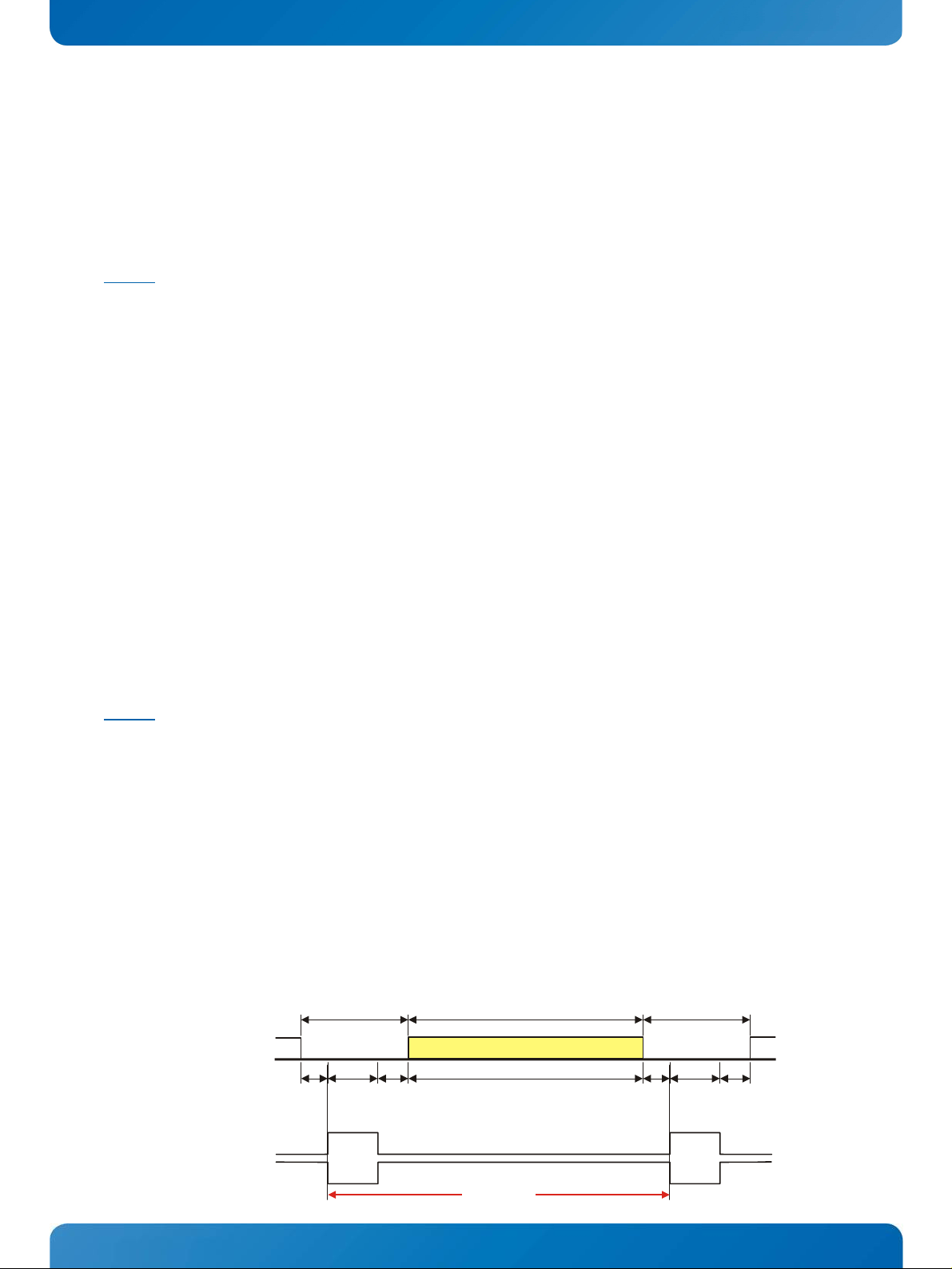
The following picture shows the typical video timing.
Timing Parameter Definitions
Blanking
Active Part
Blanking
H-/V-Video
Front
Porch
H-/V-Sync
Sync
Pulse
Width
pos.
Sync
neg.
Sync
Back
Porch
Address Time
Total
KTAM3874/pITX Software Guide
Front
Porch
Sync
Pulse
Width
pos.
Sync
neg.
Sync
Back
Porch
Page 18
KTD-S0057-I Page 14 VESA® DisplayIDTM
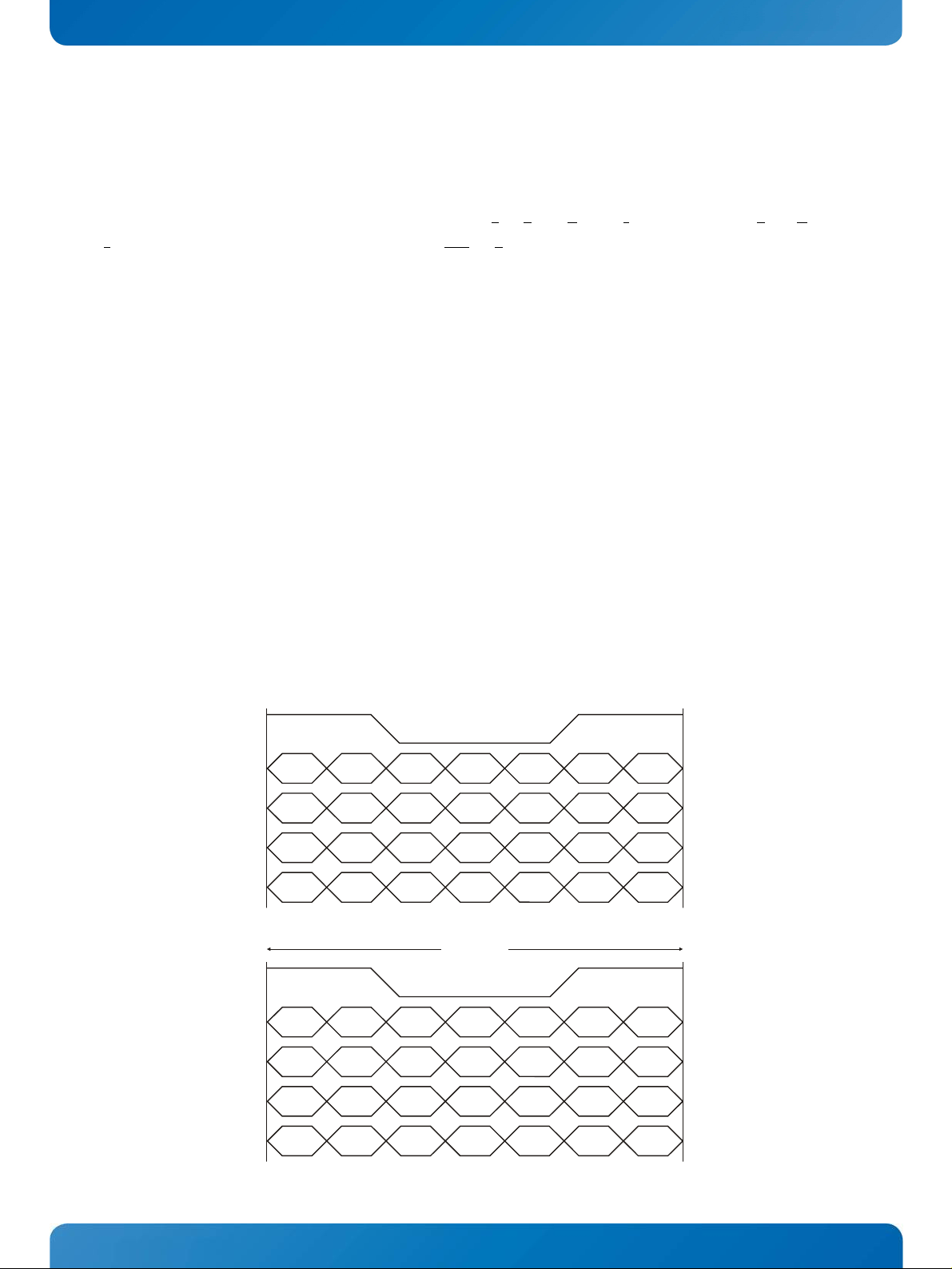
4.1.2 24 Bit Color Mapping Tips
The double pixel clock or 24-bit color depth can generally be taken from the datasheet. There are two
interface modes existing at 24-bit color depth: FPDI (F
nterface). Some panels use the line SELL LVDS (SELect Lvds data order). The LVDS data assignment in the
I
lat Panel Display Interface) or LDI (LVDS Display
datasheet can give you an indication by the last channel (e.g. RX3/TX3 – SELL LVDS = low) wether it is a LDI
panel (contains the lowest bits).
Example:
FPDI data assignment (LVDS channel 3 even or odd):
Tx/Rx27 Red 6 (e.g. even: RE6 or ER6)
Tx/Rx5 Red 7
Tx/Rx10 Green 6 (e.g. even: GE6 or EG6)
Tx/Rx11 Green 7
Tx/Rx16 Blue 6 (e.g. even: BE6 or EB6)
Tx/Rx17 Blue 7
Tx/Rx23 not used
LDI data assignment (LVDS channel 3 even or odd):
Tx/Rx27 Red 0 (e.g. even: RE0 or ER0)
Tx/Rx5 Red 1
Tx/Rx10 Green 0 (e.g. even: GE0 or EG0)
Tx/Rx11 Green 1
Tx/Rx16 Blue 0 (e.g. even: BE0 or EB0)
Tx/Rx17 Blue 1
Tx/Rx23 not used
TxClk
TxOut0
G0
R5
R4
R3
R2 R1
R0
FPDI
TxOut1
TxOut2
B1
DE
B0
VS
G5 G4 G3 G2 G1
HS
B5
B4
B3
B2
TxOut3
B7
B6
G7 G6 R7
R6
t
cycle
LDI
TxClk
TxOut0
TxOut1
G2 R7 R6 R5
B3
R4
R3
R2
G3G4G5G6G7B2
TxOut2
TxOut3
DE VS HS B7 B6 B5
B1
B0 G1 G0
R1
B4
R0
KTAM3874/pITX Software Guide
Page 19

KTD-S0057-I Page 15 VESA® DisplayIDTM
4.2 EDID 1.3 Specification (VESA
®
)
The EDID (Extended Display Identification Data) record has a fixed structure. The first 8 bytes contain the
distinctive identification 0x00, 0xFF, 0xFF, 0xFF, 0xFF, 0xFF, 0xFF, 0x00. The end of the record is marked by
the checksum (1 byte). The result of the addition of all bytes including the checksum has to be zero.
For a comprehensive support of the majority of available panels you don't need all fields of the EDID
record. The Detailed Timing Descriptor (18 bytes) is the most important field. No 24bit panels (FPDI/LDI)
are supported though. This means EDID should only be used for 18bit panels.
®
For further information please consult the official EDID specification from the VESA
comitee which has to
be payed.
4.3 DisplayID
TM
Specification (VESA®)
Intended as a replacement for all previous EDID versions DisplayIDTM contains many new features. It's a
structure with several well defined elements (tags). Not every element that is listed in the specification has
to be part of the resulting data set (basic section).
KONTRON has decided to use this selection of tags (mandatory presence).
Tag Description
0x00 Product Identification Data Block (Vendor ID, Product Code, Manufacturing Date ...)
0x03 Type I Detailed Timing Data Block (Pixel Clock, Horizontal/Vertical Data ...)
0x0C Display Device Data Block (Device Technology, Operating Mode, Color Depth ...)
0x0D Interface Power Sequencing Data Block (Power On/Off Timing)
0x0F Display Interface Data Block (Interface Type, Interface Attribute ...)
4.3.1 DisplayIDTM Parameter Summary
Only a part of the parameters used in the DisplayIDTM Windows® tool are interpreted by a specific board. The
following table shows a summary of the used parameters (valid for KTAM3874/pITX).
Group Parameter Comment
Type I Timing Pixel Clock
Type I Timing Horizontal Active
Type I Timing Horizontal Blank
Type I Timing Horizontal Sync Offset Front porch
Type I Timing Horizontal Sync Width
Type I Timing Vertical Active
Type I Timing Vertical Blank
Type I Timing Vertical Sync Offset Front porch
Type I Timing Vertical Sync Width
Display Interface 1 Bits per Pixel Color depth (18 or 24bit)
Display Interface 1 Pixel per Clock Single or dual channel
Display Interface 1 24 Bit Color Mapping FPDI or LDI
KTAM3874/pITX Software Guide
Page 20

KTD-S0057-I Page 16 VESA® DisplayIDTM
4.3.2 DisplayIDTM Restrictions
Depending on the graphic controller not all features can be used. The following table shows the most important restrictions.
Restrictions for KTAM3874/pITX
Variable power sequencing not supported
4.3.3 LCD Panel Selection
The choice of a LCD display is basically defined by two parameters.
Parameter Value
Pixel per Clock (Channels) 1 or 2
Pixel Clock Range 165 MHz
Currently this leads to a maximum resolution of
With TIs® graphic driver it is not guaranteed that every resolution can be achieved. KONTRON does not
guarantee the correct function of the board for untypical resolution. In principal the use of DisplayID
allows realizing every special display resolution. For this a valid DisplayID
onboard EEPROM. Additionally the U-Boot Setup entry
setup display x submenu [3] x Set LCD panel resolution
must be set to auto.
1920 x 1080 Pixel
TM
dataset must be written to the
TM
KTAM3874/pITX Software Guide
Page 21
KTD-S0057-I Page 17 VESA® DisplayIDTM
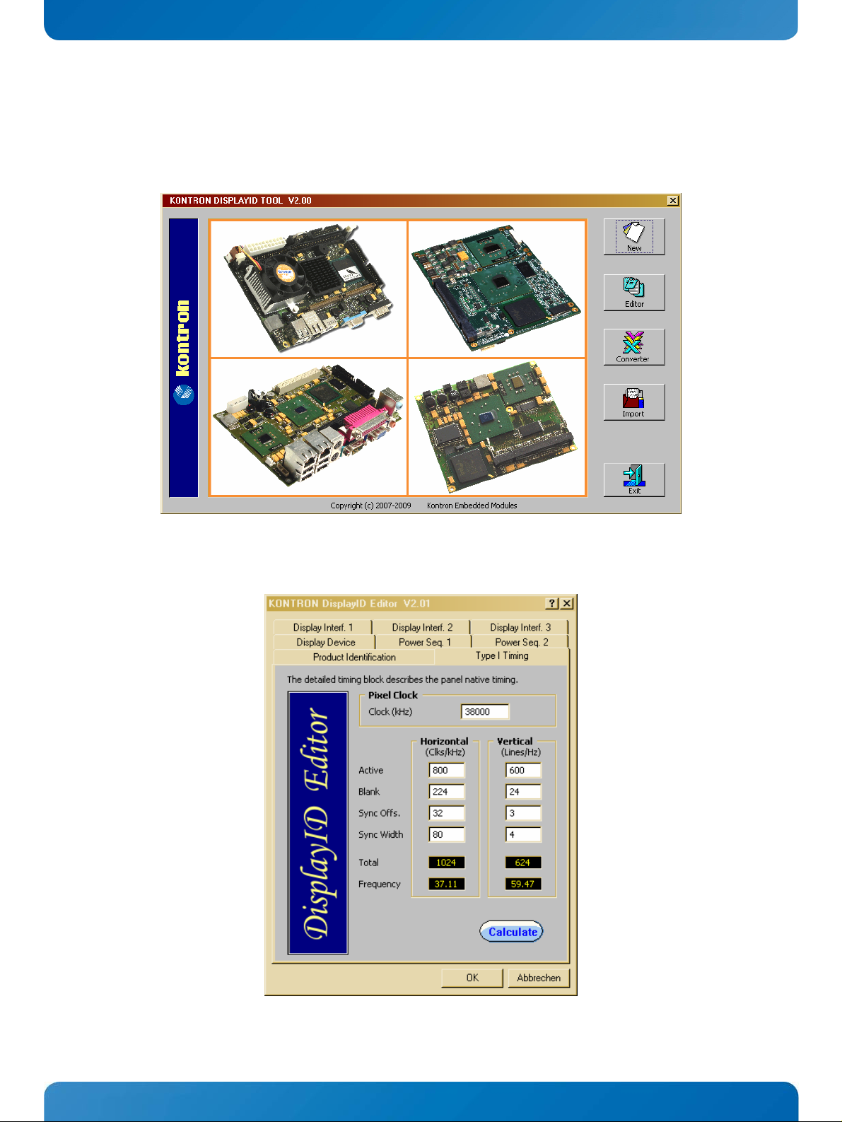
4.3.4 DisplayIDTM Windows® Tool
The DisplayIDTM parameter can be modified with the DisplayIDTM Windows® tool.
For an example the following picture shows the input fields for the Detailed Timing parameters.
For more information see the documentation of the DisplayID
kontron.com).
KTAM3874/pITX Software Guide
TM
tool (software can be downloaded from
Page 22

KTD-S0057-I Page 18 VESA® DisplayIDTM
TM
The DisplayID
isplayIDTM Data). This file format cannot be used to program the onboard EEPROM.
tron D
Editor saves the parameters in a intermediate file format. The file extension is 'KDD' (Kon-
For transferring this file format into the binary file format for the EEPROM apply the Converter.
4.3.5 Building DisplayIDTM File
Start the Windows® tool DisplayID.exe.
Use the Editor if you want to modify an existing DisplayIDTM file or select New to create a
complete new record.
Change respectively enter new parameters.
Save the parameters in a file with the extension 'KDD'.
Open the saved 'KDD'-file using the Converter.
Save the binary file with the extension 'KDB' (Kontron DisplayIDTM Binary).
Program the onboard EEPROM using the board specific update tool.
4.3.6 Erasing DisplayIDTM Record
Create a dummy file with a size of 128 bytes filled with the value 0xFFh and program this file using the U-
TM
Boot update tool. This treatment deletes a valid DisplayID
record.
4.3.7 U-Boot EEPROM Update Tool
The update tool is a new component of the U-Boot bootloader. You need two commands to program a
TM
DisplayID
file into the EEPROM:
ext2load, fatload, loadb or loady
writedid
File Operation
The following example gives an overview:
TM
The storage medium is a microSD
is located in the root directory. The file size of wvga.kdb amounts 81 bytes.
For loading the file into memory type the following standard U-Boot command lines
mmc rescan 0
ext2load mmc 0 81000000 wvga.kdb
The memory address (0x81000000) is free selectable. With the md command you can control the result
md.b 81000000 80
Now you can load the memory content into the EEPROM. Type the new KONTRON U-Boot command
writedid 81000000 51
The 'count' respectively the size argument is a very important parameter. Do not use another value as the
TM
file size of your DisplayID
file.
card formatted with a Linux® partition and the DisplayIDTM file wvga.kdb
KTAM3874/pITX Software Guide
Page 23

KTD-S0057-I Page 19 VESA® DisplayIDTM
Serial Download
The following example demonstrates a serial download via the ymodem protocol:
The KTAM3874/pITX board is connected to a desktop computer with a suitable terminal program (e.g.
Hyper-Terminal or TeraTerm). The file size of wvga.kdb amounts 81 bytes.
For downloading the file into memory type the following standard U-Boot command line
loady
Now U-Boot waits for reply. User input to the desktop terminal program starts the download session. After
the download of wvga.kdb ends you can control the result with the
md.b 80009000 80
Now you can load the memory content into the EEPROM. Type the new KONTRON U-Boot command
writedid 80009000 51
The 'count' respectively the size argument is a very important parameter. Do not use another value as the
TM
file size of your DisplayID
file.
The memory parameter of md.b and writedid depends on the environment entry loadaddr because
Note:
loady uses this definition as base address, for example if loadaddr equals 0x81000000 the new KONTRON U-
Boot command changes to
writedid 81000000 51
md command
KTAM3874/pITX Software Guide
Page 24
KTD-S0057-I Page 20 U-Boot Bootloader
5 U-Boot Bootloader
TI® requires a two-part U-Boot version. The ROM code loads the first part (named U-Boot-MIN) into the onchip prozessor RAM and starts automatically this part. After setting up the clocks and initializing all
necessary peripherals U-Boot-MIN loads the final version. The KTAM3874/pITX board offers four different
TM
load mechanisms: SPI
(default, see chapter 'SPI
For development purposes the UART and Ethernet methods promise some advantages.
5.1 UART Bootloader
The first serial port (UART0) on connector J1304 provides the serial console interface. For communication
a standard terminal program on a desktop computer is necessary (e.g. TeraTerm). The next line shows the
default serial console settings:
The UART method strictly needs a jumper on pin header J1101 (see User's Guide chapter 'Serial Console').
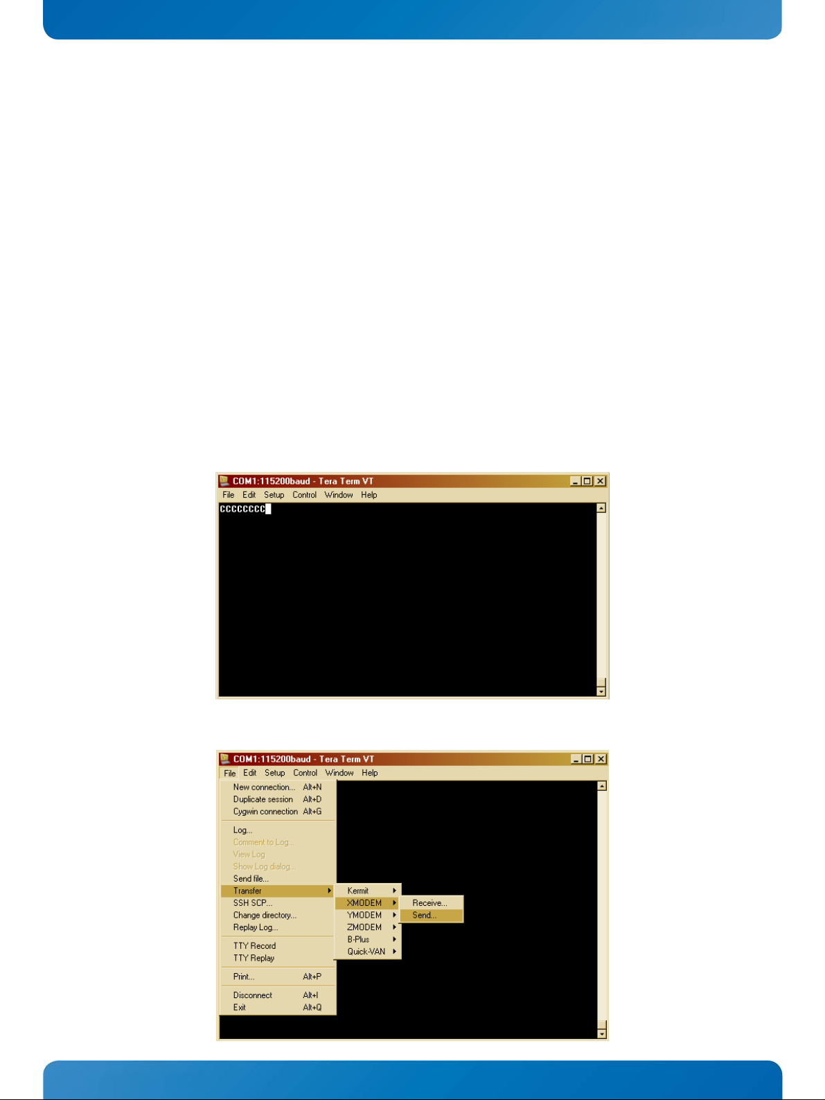
After power on the following screen appears:
115 kBaud / 8 data bits / 1 stop bit / no parity
TM
Bootloader'), MMC, Ethernet and UART.
Now you have to select the XMODEM transfer mode.
KTAM3874/pITX Software Guide
Page 25
KTD-S0057-I Page 21 U-Boot Bootloader
Note: Do not start the transmission before all eight C's are visible - otherwise the download can be confused.
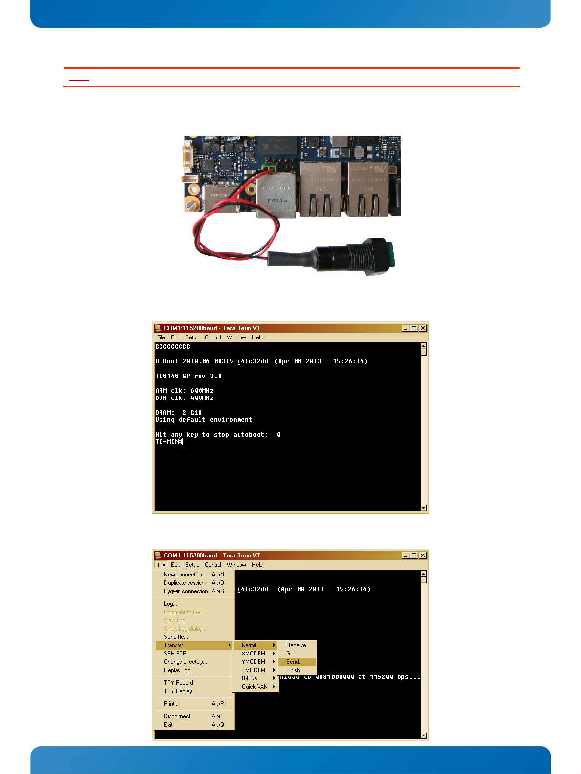
Thereafter select the U-Boot-MIN file (normally named 'u-boot.min.uart') and immediately press the Reset
button to start the download process.
The terminal program shows the following result:
Type 'loadb 81000000' at the 'TI-MIN#' prompt and press 'Enter'. Then choose the Kermit transfer mode.
KTAM3874/pITX Software Guide
Page 26
KTD-S0057-I Page 22 U-Boot Bootloader
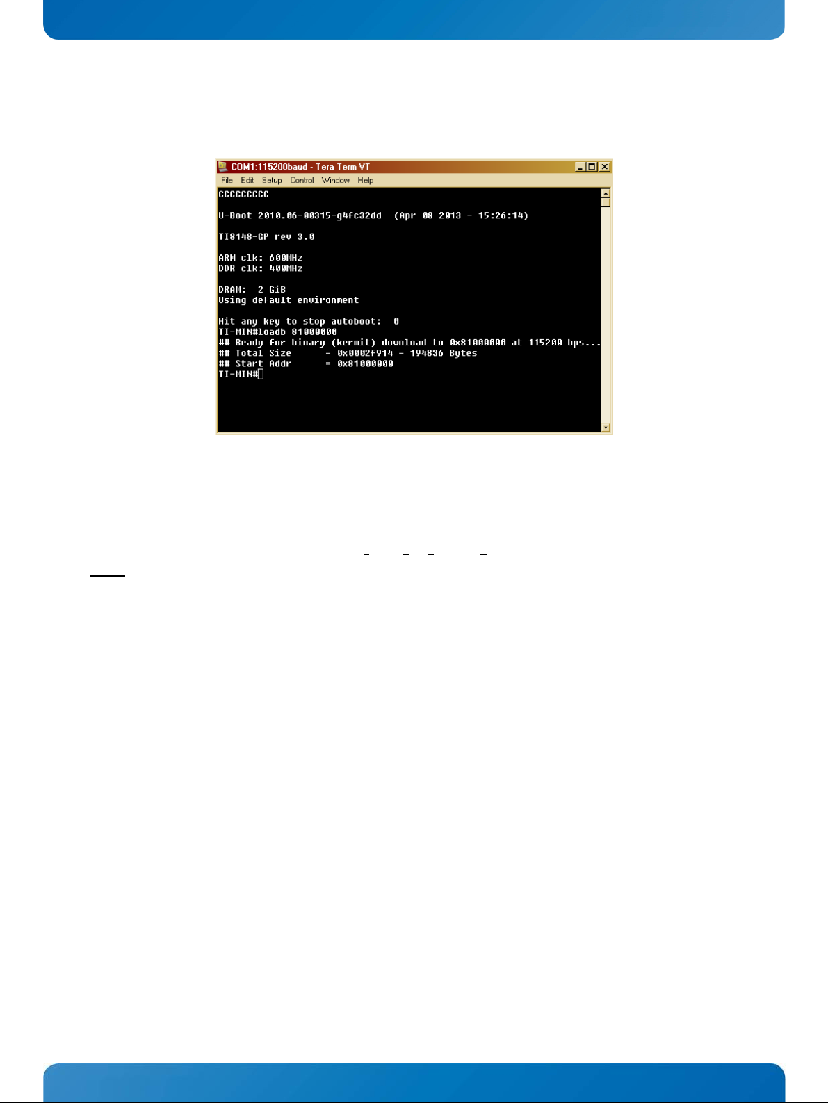
The next step is to load the final U-Boot version (normally named 'u-boot.bin'). This time the transfer
starts automatically. The result looks as follows:
Now you can start the final U-Boot version with 'go 81000000'.
5.2 Ethernet Bootloader
For download over Ethernet you need a TFTP (Trivial File Transfer Protocol) server with DHCP ability.
Use only the first Ethernet port (J1600).
Note:
Some preference changes are necessary:
This method strictly needs a jumper on pin header J1101 (see User's Guide chapter 'Serial
Console').
Rename the U-Boot-MIN file named 'u-boot.min.eth' in 'MLO'.
The ROM code tries first to load the U-Boot-MIN part over the serial interface but this approach fails.
Afterwards the ROM code etablish the Ethernet connection and loads MLO and subsequently the real UBoot version. As a result of the serial interface timeout the network connection is rather slowly.
Copy 'MLO' and u-boot.bin' into the same directory.
KTAM3874/pITX Software Guide
Page 27
KTD-S0057-I Page 23 U-Boot Bootloader
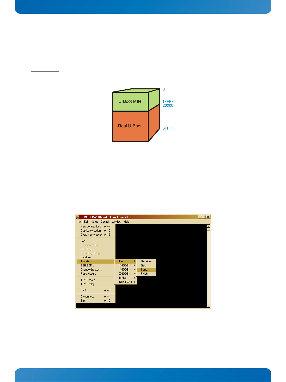
5.3 SPI
TM
Bootloader
This chapter describes the programming of the SPITM flash with the serial interface. Alternative you can load
TM
both U-Boot versions for example from the microSD
Assumption:
the default boot order is active (SPITM flash first boot device).
card.
The picture shows the fixed address ranges within the SPITM flash.
After power on U-Boot starts from SPITM. Hit any key to stop the autoboot process. As a first step you should
TM
erase the bootloader part of the SPI
flash with the following commands:
sf probe 0:0
sf erase 0 60000
Thereafter type 'loadb 81000000' at the 'KTAM3874#' prompt and press 'Enter'. Then choose the Kermit
transfer mode. Before the download you can clear the memory with
mw.b 81000000 ff 20000
Load the U-Boot-MIN file (normally named 'u-boot.min.spi') and then type
sf write 81000000 0 20000
KTAM3874/pITX Software Guide
Page 28
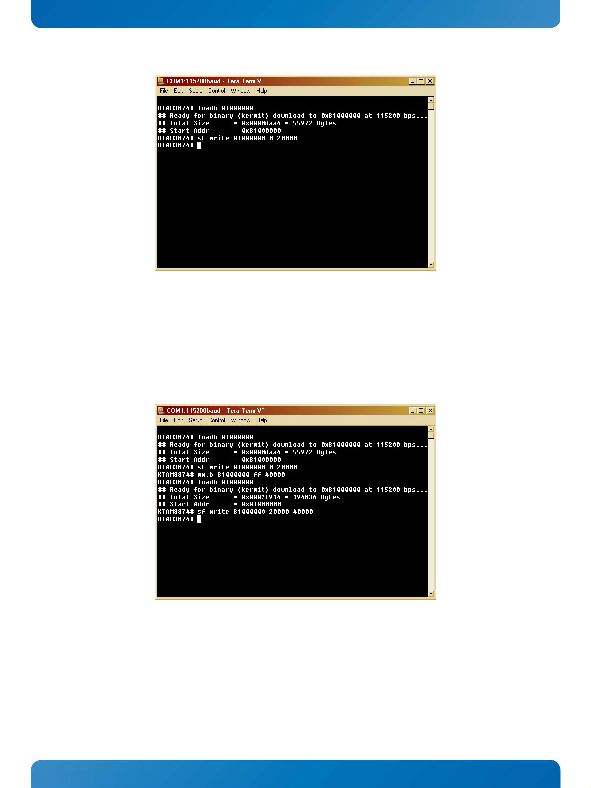
KTD-S0057-I Page 24 U-Boot Bootloader
Now the first update part is finished. For the second part type again 'loadb 81000000' at the 'KTAM3874#'
prompt and press 'Enter'. Then choose the Kermit transfer mode. Before the download you can clear the
memory with
mw.b 81000000 ff 40000
Load the real U-Boot file (normally named 'u-boot.bin') and then input with another offset and size
sf write 81000000 20000 40000
After power off and power on U-Boot-MIN loads automatically the second part. No additional steps are
necessary.
KTAM3874/pITX Software Guide
Page 29

KTD-S0057-I Page 25 U-Boot Bootloader
5.4 MMC Bootloader
For booting from the microSDTM card you have to change some preferences:
Replug the boot order jumper to MMC x SPI x ... (see User's Guide chapter 'Boot Order').
Rename the U-Boot-MIN file named 'u-boot.min.sd' in 'MLO'.
Format the microSDTM card with FAT16 or FAT32 (Linux® partitions are not accepted). For
®
previous Linux
Disk Storage Format Tool' otherwise the detection can fail.
You need an active FAT partition.
Note:
Copy 'MLO' and u-boot.bin' to the microSDTM card.
After power on U-Boot-MIN (MLO) loads automatically the second part.
formatted cards it would be advisable to use for example the 'HP® USB
KTAM3874/pITX Software Guide
Page 30

KTD-S0057-I Page 26 DebianTM Linux® BSP
6 Debian
TM
Linux® BSP
6.1 User Login Arguments
For both, serial remote system or terminal root privileges with 'sudo', the arguments are the same
(necessary input in green color):
ktam3874 login: ktam3874
Password: ktam3874
6.2 Video Decoding
The KTAM3874/pITX is not qualified for video decoding, the major focus lies on industrial applications. If
you still want to apply a video player use
MPlayer ('sudo apt-get install mplayer'). Other deployable
programs (e.g. Totem Movie Player or SMPlayer, VLC does not work with the default settings) show strong
dropouts.
For measuring the graphics performance use the
glmark2-es2 benchmark.
6.3 Audio Support
If you have trouble with audio input/output please check the 'alsamixer' settings.
Examples with the command line tool 'amixer':
First select a card with amixer -c KTAM3874 (WM8903 codec) or use amixer -c HDMI
®
(HDMI
For an overview type amixer contents
To change a value type e.g. amixer cset numid=27 on
You can find some audio files in the directory
example
aplay login.wav.
monitor). Card names are readable in the directory /proc/asound/
/usr/share/sounds/. Play these files with the 'aplay' tool, for
6.4 KEAPI Interface
The menu item 'Applications x System Tools x KEAPI' offers the practical KEAPI GUI tool. A password is
needed (default:
mentation but rather hidden.
The KEAPI GUI includes four important components: SerialBus, GPIO, Perf(ormance) and Misc(ellaneous).
TM
Three I2C
busses are selectable in the SerialBus tab:
For GPIO pin assignment see the KTAM3874/pITX User's Guide (chapter 'Digital I/O Interface'). The Perf
tab only allows the switch between 600 and 800 MHz (all available frequencies are listed in the file '/sys/
devices/system/cpu/cpu0/cpufreq/scaling_available_frequencies'). Finally the Misc tab includes the
Watchdog and System State control (only RESTART possible - TURN OFF and HIBERNATE without function).
Kontron) - this information can also be detected in the 'Kontron EAPI for Linux' docu-
#0 for onboard devices. Normally the access to these devices should be avoided - further
information on request.
#1 for the HDMI
#2 provides free access to the I2C
®
DDC EEPROM. The graphic driver blocks the access.
TM
bus at J2105 (pins 3 and 4).
KTAM3874/pITX Software Guide
Page 31

KTD-S0057-I Page 27 DebianTM Linux® BSP
6.5 CAN Bus Utilities (SocketCAN)
The directory /usr/bin contains all necessary CAN bus utilities you may need. An overview:
Utility Short Description
canbusload statistic tool
can-calc-bit-timing CAN baudrate calculation
candump shows the received message from the CAN bus, e.g. candump can0
canfdtest full-duplex test program (slave and host part)
cangen CAN frames generator for testing purpose
cangw CAN-to-CAN gateway to route (and modify) messages between multiple buses
canlogserver capture data as ASCII logfile format
canplayer send CAN frames from a file to a CAN interface
cansend send CAN-frames via CAN_RAW sockets, e.g. cansend can0 500#1E.10.10 (500 = CAN ID)
cansniffer capture and analyze CAN traffic
Additional information can be retrieved in the directory /proc/net/can. If you want to overwrite the default
baudrate of 500 kbps change the value in the file
mands (example, requires root rights):
sudo ifconfig can0 down
sudo ip link set can0 up type can bitrate 125000
After boot up it is not necessary to enter the command ifconfig can0/can1 up because this is already done.
More information about SocketCAN can be found on following webpage:
http://www.mjmwired.net/kernel/Documentation/networking/can.txt
/etc/default/can0 resp. can1 or use the following com-
6.6 S-ATA
®
Interface
The S-ATA® port supports two interfaces: either the standard L-type connector J903 or the mSATA® inter-
®
face on the mini PCI Express
tically from the connector J903 to J900 and disables the mini PCI Express
connector J900. After plug in a mSATA® card the hardware switches automa-
®
lanes.
6.7 Suspend Mode
Some of TI's® graphics drivers do not support the suspend/resume feature. Due to this limitation the board
cannot be put into suspend mode if graphics output is enabled and active.
To work around this limitation you must stop the X session and unload the graphics driver modules before
entering the suspend mode. When resuming load the modules first and start the X session afterwards.
6.8 Screensaver
The X screensaver overlays the Gnome
mode and press Enter.
TM
screensaver. In order to solve this issue type xset s off in terminal
KTAM3874/pITX Software Guide
Page 32

KTD-S0057-I Page 28 DebianTM Linux® BSP
6.9 Sysfs Support
Alternative to the KEAPI interface you can use Sysfs to manipulate the GPIOs or the backlight. The example
reads the content and direction of GPIO0 (GP0[10]) and sets the direction to 'output' and the content to
'high'.
Comment:
root@ubuntu:# echo 10 > /sys/class/gpio/export enable GP0[10] access
root@ubuntu:# cat /sys/class/gpio/gpio10/value read content
1 value = high
root@ubuntu:# cat /sys/class/gpio/gpio10/direction read direction
in direction = inpu t
root@ubuntu:# echo "out" > /sys/class/gpio/gpio10/direction set direction to output
root@ubuntu:# echo 1 > /sys/class/gpio/gpio10/value set content to high
root@ubuntu:# echo 10 > /sys/class/gpio/unexport disable GP0[10] access
KTAM3874/pITX Software Guide
Page 33

KTD-S0057-I Page 29 Ethernet Switch
7 Ethernet Switch
TI®'s AM3874 SoC knows two different Ethernet operating modes: the normal dual port and the optional
three port switch
brought out externally on connector J1600 respectively J1601. You can choose between both modes with
an additional U-Boot environment variable (default: dual port mode if the variable is absent).
The environment argument default_bootargs represents a good place for attachment with the U-Boot
command
editenv. Do not forget to save this setting using the command saveenv.
The following picture shows an example with three boards which have at least one free port. There is no
difference between the connectors J1600 and J1601.
setting. The switch contains one port with internal connection and two ports which are
dual_emac=0 $ Three port switch mode
dual_emac=1
Dual port mode
$
For detection of the actual mode use the command ifconfig within Linux
see only
eth0 and for dual port mode eth0/eth1.
®
. As a result for switch mode you
There are no restrictions regarding the connection of other computer boards for example an x86 board with
®
the Windows
operating system.
KTAM3874/pITX Software Guide
Page 34

KTD-S0057-I Page 30 Kernel Boot from SPITM Flash
8 Kernel Boot from SPI
TM
Flash
In some cases it is necessary to program the Linux® kernel into the SPITM flash. U-Boot cannot boot the
®
kernel from the S-ATA
or USB interface (for S-ATA® example see next chapter). The most obvious option
insists in the use of the U-Boot flash command 'sf'.
# sf probe 0:0
4096 KiB SST25VF032B at 0:0 is now current device
# mw.b 81000000 ff 320000
# loadb 81000000
Ready for binary (kermit) download to 0x81000000 at 115200 bps...
Total Size = ... = ... Bytes
Start Addr = 0x81000000
# sf write 81000000 e2000 31e000
The following picture shows the SPITM flash structure:
Note:
The SPITM flash boot requires an additional modification in the U-Boot environment.
loadaddr = 0x81000000
Another option represents the programming of the SPITM flash within the Linux® operating system (e.g.
TM
boot from microSD
# cat /proc/partitions
major minor #blocks name
31 0 128 mtdblock0
31 1 256 mtdblock1
31 2 8 mtdblock2
31 3 512 mtdblock3
31 4 3192 mtdblock4
179 0 7761920 mmcblk0
179 1 7757824 mmcblk0p1
.........
card). First check the partition layout with
KTAM3874/pITX Software Guide
Page 35

KTD-S0057-I Page 31 Root File System Boot from S-ATA® Drive
Thereafter type the following line
# sudo dd if=/boot/uImage of=/dev/mtdblock4
4626+1 records in
4626+1 records out
... bytes (... MB) copied, ... s, 46.0 kB/s
9 Root File System Boot from S-ATA
®
Drive
The S-ATA® part (mSATA® or standard S-ATA® connector) offers the fastest board interface. This is the only
way of achieving transfer rates about 150 MB/s, normally only with SSD drives. The kernel does not
automatically mount the drive therefore you have to modify the configuration file
etc/fstab (per default
this file is empty). The example uses a freely chosen drive identifier (sda1) and target directory.
# UNCONFIGURED FSTAB FOR BASE SYSTEM
/dev/sda1 /media/sata ext4 defaults 0 1
After update you should create the new directory /media/sata. But this method has a serious disadvantage:
if you remove the drive the kernel stops with an error message.
Furthermore the U-Boot environment needs an additional modification:
spiboot =setenv root_bootargs root=/dev/sda1 rw rootwait;run setbootarg;sf probe 0 && sf read ${loadaddr}
0xE2000 0x31E000 && bootm ${loadaddr}
KTAM3874/pITX Software Guide
Page 36

KTD-S0057-I Page 32 Linux® Programming Examples (DebianTM)
10 Linux
10.1 TI
®
®
Programming Examples (DebianTM)
AM3874 Register Access
With the simple known program devmem2 you can read and write all registers of TI
following sourcecode for
TM
distribution).
tu
/*
* devmem2.c: Simple program to read/write from/to any location in memory.
* Copyright (C) 2000, Jan-Derk Bakker (J.D.Bakker@its.tudelft.nl)
* This software has been developed for the LART computing board
* (http://www.lart.tudelft.nl/). The development has been sponsored by
* the Mobile MultiMedia Communications (http://www.mmc.tudelft.nl/)
* and Ubiquitous Communications (http://www.ubicom.tudelft.nl/)
* projects.
* The author can be reached at:
* Jan-Derk Bakker
* Information and Communication Theory Group
* Faculty of Information Technology and Systems
* Delft University of Technology
* P.O. Box 5031
* 2600 GA Delft
* The Netherlands
* This program is free software; you can redistribute it and/or modify
* it under the terms of the GNU General Public License as published by
* the Free Software Foundation; either version 2 of the License, or
* (at your option) any later version.
* This program is distributed in the hope that it will be useful,
* but WITHOUT ANY WARRANTY; without even the implied warranty of
* MERCHANTABILITY or FITNESS FOR A PARTICULAR PURPOSE. See the
* GNU General Public License for more details.
* You should have received a copy of the GNU General Public License
* along with this program; if not, write to the Free Software
* Foundation, Inc., 59 Temple Place, Suite 330, Boston, MA 02111-1307 USA
*/
#include <stdio.h>
#include <stdlib.h>
#include <string.h>
#include <errno.h>
#include <fcntl.h>
#include <sys/mman.h>
#define FATAL do { fprintf(stderr, "Error at line %d, file %s (%d) [%s]\n", \
__LINE__, __FILE__, errno, strerror(errno)); exit(1); } while(0)
#define MAP_SIZE 4096UL
#define MAP_MASK (MAP_SIZE - 1)
devmem2 contains some differences to the original program (compiled on Ubun-
®
's AM3874 SoC. The
KTAM3874/pITX Software Guide
Page 37

KTD-S0057-I Page 33 Linux® Programming Examples (DebianTM)
int main (int argc, char **argv)
{
int fd;
void *map_base, *virt_addr;
unsigned long read_result, writeval;
off_t target;
int access_type = 'd';
if (argc < 2)
{
fprintf (stderr, "\nUsage:\t%s {address} [type [data]]\n"
"\taddress : memory address to act upon\n"
"\ttype : access operation type : [b]yte, [w]ord, [d]word\n"
"\tdata : data to be written\n\n", argv[0]);
exit (1);
}
target = strtoul (argv[1], NULL, 16);
if (argc > 2)
access_type = tolower (argv[2][0]);
if ((fd = open ("/dev/mem", O_RDWR | O_SYNC)) == -1) FATAL;
map_base = mmap (0, MAP_SIZE, PROT_READ | PROT_WRITE, MAP_SHARED, fd, target & ~MAP_MASK);
if (map_base == (void *) -1) FATAL;
virt_addr = map_base + (target & MAP_MASK);
switch (access_type)
{
case 'b': read_result = *((unsigned char *) virt_addr); break;
case 'w': read_result = *((unsigned short *) virt_addr); break;
case 'd': read_result = *((unsigned long *) virt_addr); break;
default : fprintf (stderr, "Illegal data type '%c'.\n", access_type); exit (2);
}
printf ("Value at address 0x%lX: 0x%lX\n", target, read_result);
fflush (stdout);
if (argc > 3)
{
writeval = strtoul (argv[3], NULL, 16);
switch (access_type)
{
case 'b': *((unsigned char *) virt_addr) = writeval;
read_result = *((unsigned char *) virt_addr);
break;
case 'w': *((unsigned short *) virt_addr) = writeval;
read_result = *((unsigned short *) virt_addr);
break;
case 'd': *((unsigned long *) virt_addr) = writeval;
read_result = *((unsigned long *) virt_addr);
break;
}
printf ("Written: 0x%lX - Readback: 0x%lX\n", writeval, read_result);
fflush (stdout);
}
K
KTAM3874/pITX Software Guide
Page 38

KTD-S0057-I Page 34 Linux® Programming Examples (DebianTM)
if (munmap (map_base, MAP_SIZE) == -1) FATAL;
close (fd);
return 0;
}
The following lines demonstrate the access to an AM3874 register (all values are hexadecimal):
Read the GPIO port 0 debounce register ./devmem2 48032150
Enable debouncing of GP0[10] (write access) ./devmem2 48032150 d 400
You need root rights for use of 'devmem2'.
ATTENTION
10.1.1 Register Access Restrictions
The functionality of the GPIO connectors deserves special interest. You can use the respective device driver
interface or for more flexibility direct register access (e.g. with 'devmem2'). The table shows two cases
where the register access fails.
Function Short Desciption Memory Address Direct Access
I2C2
SPI2
SPI3
UART2
UART4
TIM4
TIM5
TIM6
TIM7
I2CTM - 3rd controller 0x4819C000
SPITM - 3rd controller 0x481A2000
SPITM - 4th controller 0x481A4000
UART - 3rd controller 0x48024000
UART - 5th controller 0x481A8000
Timer 4 0x48044000
Timer 5 0x48046000
Timer 6 0x48048000
Timer 7 0x4804A000
YES
NO
NO
YES
YES
YES
YES
YES
YES
TM
The problem with the SPI
disabled. You can solve this issue with the following register programming (needed root rights):
Enable clock domain in CM_ALWON_SPI_CLKCTRL ./devmem2 48181590 d 30002
interface resides in the fact that outside of the device driver the clock domain is
Now all SPITM registers are fully accessible.
KTAM3874/pITX Software Guide
Page 39

KTD-S0057-I Page 35 Linux® Programming Examples (DebianTM)
10.2 SPI
TM
Interface Examples
10.2.1 SPITM Loopback Test Utility
A simple way to check the SPITM interface consists in shorting of the data lines (MISO, MOSI). After that you
TM
can use the following program with root rights (compiled on Ubuntu
/*
* SPI testing utility (using spidev driver)
* Copyright (c) 2007 MontaVista Software, Inc.
* Copyright (c) 2007 Anton Vorontsov
* This program is free software; you can redistribute it and/or modify
* it under the terms of the GNU General Public License as published by
* the Free Software Foundation; either version 2 of the License.
*/
#include <stdint.h>
#include <stdio.h>
#include <stdlib.h>
#include <getopt.h>
#include <fcntl.h>
#include <sys/ioctl.h>
#include <linux/spi/spidev.h>
#define ARRAY_SIZE(a) (sizeof(a) / sizeof((a)[0]))
static const char *device = "/dev/spidev3.0"; /* Connector J2105 pin 5 to 8 */
/****** Do not forget to enable SPI3 (= spidev4.0) in U-Boot Setup ******/
/*static const char *device = "/dev/spidev4.0";*/ /* Connector J2105 pin 23 to 26 */
static uint8_t mode = 0;
static uint8_t bits = 8;
static uint32_t speed = 1000000;
static uint16_t delay;
static void pabort (const char *s)
{
perror (s);
abort ();
}
static void transfer (int fd)
{
int ret;
uint8_t tx[] = {
0xFF, 0xFF, 0xFF, 0xFF, 0xFF, 0xFF,
0x40, 0x00, 0x00, 0x00, 0x00, 0x95,
0xFF, 0xFF, 0xFF, 0xFF, 0xFF, 0xFF,
0xFF, 0xFF, 0xFF, 0xFF, 0xFF, 0xFF,
0xFF, 0xFF, 0xFF, 0xFF, 0xDE, 0xAD,
0xBE, 0xEF, 0xBA, 0xAD, 0xF0, 0x0D };
distribution):
KTAM3874/pITX Software Guide
Page 40

KTD-S0057-I Page 36 Linux® Programming Examples (DebianTM)
uint8_t rx[ARRAY_SIZE(tx)] = {0, };
struct spi_ioc_transfer tr = {
.tx_buf = (unsigned long) tx,
.rx_buf = (unsigned long) rx,
.len = ARRAY_SIZE(tx),
.delay_usecs = delay,
.speed_hz = 0,
.bits_per_word = 0 };
ret = ioctl (fd, SPI_IOC_MESSAGE (1), &tr);
if (ret == 1)
pabort ("Cannot send SPI message");
for (ret = 0; ret < ARRAY_SIZE(tx); ret++)
{
if (! (ret % 6))
puts ("");
printf ("%.2X ", rx[ret]);
}
puts ("");
}
void print_usage (const char *prog)
{
printf ("Usage: %s [-DsbdHOC]\n", prog);
puts (" -D --device device to use (default /dev/spidev1.1)\n"
" -s --speed max speed (Hz)\n"
" -d --delay delay (usec)\n"
" -b --bpw bits per word \n"
" -H --cpha clock phase\n"
" -O --cpol clock polarity\n"
" -C --cs-high chip select active high\n");
exit (1);
}
void parse_opts (int argc, char *argv[])
{
while (1)
{
static const struct option lopts[] = {
{ "device", 1, 0, 'D' },
{ "speed", 1, 0, 's' },
{ "delay", 1, 0, 'd' },
{ "bpw", 1, 0, 'b' },
{ "cpha", 0, 0, 'H' },
{ "cpol", 0, 0, 'O' },
{ "cs-high", 0, 0, 'C' },
{ NULL, 0, 0, 0 }};
int c;
c = getopt_long (argc, argv, "D:s:d:b:HOC", lopts, NULL);
if (c == -1) break;
KTAM3874/pITX Software Guide
Page 41

KTD-S0057-I Page 37 Linux® Programming Examples (DebianTM)
switch (c)
{
case 'D': device = optarg; break;
case 's': speed = atoi (optarg); break;
case 'd': delay = atoi (optarg); break;
case 'b': bits = atoi (optarg); break;
case 'H': mode |= SPI_CPHA; break;
case 'O': mode |= SPI_CPOL; break;
case 'C': mode |= SPI_CS_HIGH; break;
default: print_usage (argv[0]); break;
}
}
}
int main (int argc, char *argv[])
{
int ret = 0;
int fd;
parse_opts (argc, argv);
fd = open (device, O_RDWR);
if (fd < 0)
pabort ("Cannot open device");
/* SPI mode */
ret = ioctl (fd, SPI_IOC_WR_MODE, &mode);
if (ret == -1)
pabort ("Cannot set SPI mode");
ret = ioctl (fd, SPI_IOC_RD_MODE, &mode);
if (ret == -1)
pabort ("Cannot get SPI mode");
/* Bits per word */
ret = ioctl (fd, SPI_IOC_WR_BITS_PER_WORD, &bits);
if (ret == -1)
pabort ("Cannot set bits per word");
ret = ioctl (fd, SPI_IOC_RD_BITS_PER_WORD, &bits);
if (ret == -1)
pabort ("Cannot get bits per word");
/* Max speed in Hz */
ret = ioctl (fd, SPI_IOC_WR_MAX_SPEED_HZ, &speed);
if (ret == -1)
pabort ("Cannot set max speed in Hz");
ret = ioctl (fd, SPI_IOC_RD_MAX_SPEED_HZ, &speed);
if (ret == -1)
pabort ("Cannot get max speed in Hz");
printf ("SPI mode: %d\n", mode);
printf ("Bits per word: %d\n", bits);
printf ("Max speed: %d Hz (%d kHz)\n", speed, speed/1000);
KTAM3874/pITX Software Guide
Page 42

KTD-S0057-I Page 38 Linux® Programming Examples (DebianTM)
transfer (fd);
close (fd);
return ret;
}
You should consider following parameter limits:
Parameter MIN MAX Units
Databits (Bits per Word) 4
Transmission Speed 2000
Transmission Mode Only full duplex possible (driver restriction)
Bit Transfer Mode Only MSB first mode possible
The test array of the original sourcecode contains 38 bytes but this number can cause a crash if you
Note:
use 32 data bits (number should be 36 bytes).
Further information is available on
Examples:
Using default values ./spi
Set speed to 10 MHz ./spi -s 10000000
Set mode to 3 ./spi -H -O
https://www.kernel.org/doc/Documentation/spi/spi-summary.
As result you should see this screen output:
32
48000000
Bits
Hz
KTAM3874/pITX Software Guide
Page 43

KTD-S0057-I Page 39 Linux® Programming Examples (DebianTM)
10.2.2 SPITM Display Interface
The SPITM interface is well suited to connect uncomplicated intelligent small graphic modules for example
The schematic below shows the connection to I/O connector J2105 pin 5 to 8 (SPI2). Please notice that this
draft only serves for demonstration purposes but not for real applications.
Electronic Assembly eDIP128-6.
In general the following pinout applies for all SPITM interfaces:
D0 $ MISO (Master In Slave Out = Receive)
D1 $ MOSI (Master Out Slave In = Transmit)
Note: Please perform a RESET before you execute the test program.
KTAM3874/pITX Software Guide
Page 44

KTD-S0057-I Page 40 Linux® Programming Examples (DebianTM)
Now the corresponding test program (needs root rights):
/* SPI test program for
* Electronic Assembly graphic module eDIP128-6
* Copyright (c) 2013 Kontron Technology A/S
* This program is free software; you can redistribute it and/or modify
* it under the terms of the GNU General Public License as published by
* the Free Software Foundation; either version 2 of the License.
*/
#include <stdint.h>
#include <stdio.h>
#include <stdlib.h>
#include <getopt.h>
#include <fcntl.h>
#include <sys/ioctl.h>
#include <linux/spi/spidev.h>
#define ARRAY_SIZE(a) (sizeof(a) / sizeof((a)[0]))
#define SPI_OPEN_ERROR 0x10
#define SPI_MODE_ERROR 0x11
#define SPI_BITS_ERROR 0x12
#define SPI_SPEED_ERROR 0x13
static const char *device = "/dev/spidev3.0";
/****** Do not forget to enable SPI3 (= spidev4.0) in U-Boot Setup ******/
/*static const char *device = "/dev/spidev4.0";*/
static uint8_t mode = 3;
static uint8_t bits = 8;
static uint32_t speed = 100000;
static uint16_t delay = 10;
static int fd;
static int transmit_spi_test_string (void)
{
uint8_t tx[] = {
0x11, /* DC1 */
0x05, /* Data len */
0x48, 0x65, 0x6C, 0x6C, 0x6F, /* Data = 'Hello' */
0x0A /* Checksum */
};
struct spi_ioc_transfer xfer = {
.tx_buf = (unsigned long) tx,
.rx_buf = (unsigned long) NULL,
.len = ARRAY_SIZE(tx),
.delay_usecs = delay,
.speed_hz = 0,
.bits_per_word = 0 };
if (ioctl (fd, SPI_IOC_MESSAGE (1), &xfer) == 1)
return -1;
return 0;
}
KTAM3874/pITX Software Guide
Page 45

KTD-S0057-I Page 41 Linux® Programming Examples (DebianTM)
int init_spi_interface (void)
{
fd = open (device, O_RDWR);
if (fd < 0)
return SPI_OPEN_ERROR;
if (ioctl (fd, SPI_IOC_WR_MODE, &mode) == -1)
return SPI_MODE_ERROR;
if (ioctl (fd, SPI_IOC_WR_BITS_PER_WORD, &bits) == -1)
return SPI_BITS_ERROR;
if (ioctl (fd, SPI_IOC_WR_MAX_SPEED_HZ, &speed) == -1)
return SPI_SPEED_ERROR;
return 0;
}
int main (void)
{
int ret;
printf ("\nSPI Test for eDIP128-6\n");
if ((ret = init_spi_interface ()))
{
close (fd);
printf ("SPI init error: 0x%02X\n\n", ret);
return -1;
}
if (transmit_spi_test_string ())
{
close (fd);
printf ("SPI transmission fails!\n\n");
return -1;
}
close (fd);
printf ("SPI transmission successfully finished.\n\n");
return 0;
}
KTAM3874/pITX Software Guide
Page 46

KTD-S0057-I Page 42 Linux® Programming Examples (DebianTM)
10.3 I
2CTM
Interface Examples
10.3.1 I2CTM Detection Utility
The following sourcecode represents an optimized lean version of the standard I2CTM detection program
TM
without unnecessary overhead (compiled on Ubuntu
/*
i2cdetect.c - a user-space program to scan for I2C devices
Copyright (C) 1999-2004 Frodo Looijaard <frodol@dds.nl>, and
Mark D. Studebaker <mdsxyz123@yahoo.com>
Copyright (C) 2004-2012 Jean Delvare <khali@linux-fr.org>
This program is free software; you can redistribute it and/or modify
it under the terms of the GNU General Public License as published by
the Free Software Foundation; either version 2 of the License, or
(at your option) any later version.
This program is distributed in the hope that it will be useful,
but WITHOUT ANY WARRANTY; without even the implied warranty of
MERCHANTABILITY or FITNESS FOR A PARTICULAR PURPOSE. See the
GNU General Public License for more details.
You should have received a copy of the GNU General Public License
along with this program; if not, write to the Free Software
Foundation, Inc., 51 Franklin Street, Fifth Floor, Boston,
MA 02110-1301 USA.
*/
#include <errno.h>
#include <string.h>
#include <stdio.h>
#include <stdlib.h>
#include <fcntl.h>
#include <linux/types.h>
#define MODE_AUTO 0
#define MODE_QUICK 1
#define MODE_READ 2
#define MODE_FUNC 3
#define I2C_FUNC_I2C 0x00000001
#define I2C_FUNC_10BIT_ADDR 0x00000002
#define I2C_FUNC_PROTOCOL_MANGLING 0x00000004
#define I2C_FUNC_SMBUS_PEC 0x00000008
#define I2C_FUNC_SMBUS_BLOCK_PROC_CALL 0x00008000
#define I2C_FUNC_SMBUS_QUICK 0x00010000
#define I2C_FUNC_SMBUS_READ_BYTE 0x00020000
#define I2C_FUNC_SMBUS_WRITE_BYTE 0x00040000
#define I2C_FUNC_SMBUS_READ_BYTE_DATA 0x00080000
#define I2C_FUNC_SMBUS_WRITE_BYTE_DATA 0x00100000
#define I2C_FUNC_SMBUS_READ_WORD_DATA 0x00200000
#define I2C_FUNC_SMBUS_WRITE_WORD_DATA 0x00400000
#define I2C_FUNC_SMBUS_PROC_CALL 0x00800000
distribution, needs root rights).
KTAM3874/pITX Software Guide
Page 47

KTD-S0057-I Page 43 Linux® Programming Examples (DebianTM)
#define I2C_FUNC_SMBUS_READ_BLOCK_DATA 0x01000000
#define I2C_FUNC_SMBUS_WRITE_BLOCK_DATA 0x02000000
#define I2C_FUNC_SMBUS_READ_I2C_BLOCK 0x04000000
#define I2C_FUNC_SMBUS_WRITE_I2C_BLOCK 0x08000000
#define I2C_SMBUS_READ 1
#define I2C_SMBUS_BYTE 1
#define I2C_SLAVE 0x0703
#define I2C_FUNCS 0x0705
#define I2C_SMBUS 0x0720
#define I2C_SMBUS_BLOCK_MAX 32
struct func
{
long value;
const char* name;
};
union i2c_smbus_data
{
__u8 byte;
__u16 word;
__u8 block[I2C_SMBUS_BLOCK_MAX + 2];
};
struct i2c_smbus_ioctl_data
{
char read_write;
__u8 command;
int size;
union i2c_smbus_data *data;
};
static void help (void)
{
fprintf (stderr, "Usage: i2cdetect [I2CBUS] [FIRST LAST]\n"
}
static inline __s32 i2c_smbus_access (int file, char read_write, __u8 command,
int size, union i2c_smbus_data *data)
{
struct i2c_smbus_ioctl_data args;
args.read_write = read_write;
args.command = command;
args.size = size;
args.data = data;
return ioctl (file, I2C_SMBUS, &args);
}
" i2cdetect -F [I2CBUS]\n"
" I2CBUS is an integer or an I2C bus name\n"
" If provided, FIRST and LAST limit the probing range.\n");
KTAM3874/pITX Software Guide
Page 48

KTD-S0057-I Page 44 Linux® Programming Examples (DebianTM)
static inline __s32 i2c_smbus_read_byte (int file)
{
union i2c_smbus_data data;
if (i2c_smbus_access (file, I2C_SMBUS_READ, 0, I2C_SMBUS_BYTE, &data))
return -1;
else
return 0x0FF & data.byte;
}
static int scan_i2c_bus (int file, int mode, int first, int last)
{
int i, j;
printf (" 0 1 2 3 4 5 6 7 8 9 a b c d e f\n");
for (i = 0; i < 128; i += 16)
{
printf ("%02x: ", i);
for (j = 0; j < 16; j++)
{
fflush (stdout);
/* Skip unwanted addresses */
if (i+j < first || i+j > last)
{
printf (" "); continue;
}
/* Set slave address */
if (ioctl (file, I2C_SLAVE, i+j) < 0)
{
if (errno == EBUSY)
{
printf ("UU "); continue;
}
else
{
/* ERROR: Could not set address */
printf ("** "); continue;
}
}
/* Probe this address */
/* This is known to lock SMBus on various write-only chips (mainly clock chips) */
if (i2c_smbus_read_byte (file) < 0)
printf ("-- ");
else
printf ("%02x ", i+j);
}
printf ("\n");
}
return 0;
}
KTAM3874/pITX Software Guide
Page 49

KTD-S0057-I Page 45 Linux® Programming Examples (DebianTM)
static const struct func all_func[] = {
{ .value = I2C_FUNC_I2C,
.name = "I2C" },
{ .value = I2C_FUNC_SMBUS_QUICK,
.name = "SMBus Quick Command" },
{ .value = I2C_FUNC_SMBUS_WRITE_BYTE,
.name = "SMBus Send Byte" },
{ .value = I2C_FUNC_SMBUS_READ_BYTE,
.name = "SMBus Receive Byte" },
{ .value = I2C_FUNC_SMBUS_WRITE_BYTE_DATA,
.name = "SMBus Write Byte" },
{ .value = I2C_FUNC_SMBUS_READ_BYTE_DATA,
.name = "SMBus Read Byte" },
{ .value = I2C_FUNC_SMBUS_WRITE_WORD_DATA,
.name = "SMBus Write Word" },
{ .value = I2C_FUNC_SMBUS_READ_WORD_DATA,
.name = "SMBus Read Word" },
{ .value = I2C_FUNC_SMBUS_PROC_CALL,
.name = "SMBus Process Call" },
{ .value = I2C_FUNC_SMBUS_WRITE_BLOCK_DATA,
.name = "SMBus Block Write" },
{ .value = I2C_FUNC_SMBUS_READ_BLOCK_DATA,
.name = "SMBus Block Read" },
{ .value = I2C_FUNC_SMBUS_BLOCK_PROC_CALL,
.name = "SMBus Block Process Call" },
{ .value = I2C_FUNC_SMBUS_PEC,
.name = "SMBus PEC" },
{ .value = I2C_FUNC_SMBUS_WRITE_I2C_BLOCK,
.name = "I2C Block Write" },
{ .value = I2C_FUNC_SMBUS_READ_I2C_BLOCK,
.name = "I2C Block Read" },
{ .value = 0, .name = "" }
};
static void print_functionality (unsigned long funcs)
{
int i;
for (i = 0; all_func[i].value; i++)
{
printf ("%-32s %s\n", all_func[i].name, (funcs & all_func[i].value) ? "yes" : "no");
}
}
KTAM3874/pITX Software Guide
Page 50

KTD-S0057-I Page 46 Linux® Programming Examples (DebianTM)
int open_i2c_dev (const int i2cbus, char *filename, const int quiet)
{
int file;
sprintf (filename, "/dev/i2c-%d", i2cbus);
file = open (filename, O_RDWR);
if (file < 0 && !quiet)
{
if (errno == ENOENT)
fprintf (stderr, "Error: Could not open file `/dev/i2c-%d': %s\n", i2cbus, strerror (ENOENT));
else
{
fprintf (stderr, "Error: Could not open file `%s': %s\n", filename, strerror (errno));
if (errno == EACCES)
fprintf (stderr, "Run as root?\n");
}
}
return file;
}
int main (int argc, char *argv[])
{
int i2cbus = 3; /* Default I2C bus on J2105 */
int file, res;
char filename[20];
unsigned long funcs;
int mode = MODE_READ; /* Quick mode not supported */
int first = 0x03, last = 0x77;
int flags = 0;
/* Handle (optional) flags first */
while (1+flags < argc && argv[1+flags][0] == '-')
{
switch (argv[1+flags][1])
{
case 'F': mode = MODE_FUNC; break;
default
help ();
return -1;
}
flags++;
}
if (argc >= flags + 2)
{
i2cbus = atoi (argv[flags+1]);
if ((i2cbus < 1) || (i2cbus > 4))
{
fprintf (stderr, "Error: No valid number for i2c-bus!\n");
return -1;
}
}
: fprintf (stderr, "Error: Unsupported option \"%s\"!\n", argv[1+flags]);
KTAM3874/pITX Software Guide
Page 51

KTD-S0057-I Page 47 Linux® Programming Examples (DebianTM)
/* Read address range if present */
if (argc == flags + 4 && mode != MODE_FUNC)
{
int tmp;
tmp = (int) strtoul (argv[flags+2], NULL, 16);
if ((tmp < first) || (tmp > last))
{
fprintf (stderr, "Error: FIRST argument out of range (0x%02x-0x%02x)!\n", first, last);
return -1;
}
first = tmp;
tmp = (int) strtoul (argv[flags+3], NULL, 16);
if ((tmp < first) || (tmp > last))
{
fprintf (stderr, "Error: FIRST argument out of range (0x%02x-0x%02x)!\n", first, last);
return -1;
}
last = tmp;
}
file = open_i2c_dev (i2cbus, filename, 0);
if (file < 0)
return -1;
/* Special case, we only list the implemented functionalities */
if (mode == MODE_FUNC)
{
if (ioctl (file, I2C_FUNCS, &funcs) < 0)
{
fprintf (stderr, "Error: Could not get the adapter functionality matrix: %s\n", strerror (errno));
close (file);
return -1;
}
close (file);
printf ("Functionalities implemented by %s:\n", filename);
print_functionality (funcs);
return 0;
}
res = scan_i2c_bus (file, mode, first, last);
close (file);
exit (res?1:0);
}
2CTM
Further information about the I
dev-interface
.
bus is available on https://www.kernel.org/doc/Documentation/i2c/
KTAM3874/pITX Software Guide
Page 52

KTD-S0057-I Page 48 Linux® Programming Examples (DebianTM)
10.3.2 I2CTM Display Interface
The graphic module from Electronic Assembly can also be driven via the I2CTM bus. The schematic is a bit
different. Please notice that this draft only serves for demonstration purposes but not for real applications.
Note: Please perform a RESET before you execute the test program.
The sourcecode is based on the SPI
/* I2C test program for
* Electronic Assembly graphic module eDIP128-6
* Copyright (c) 2013 Kontron Technology A/S
* This program is free software; you can redistribute it and/or modify
* it under the terms of the GNU General Public License as published by
* the Free Software Foundation; either version 2 of the License.
*/
#include <errno.h>
#include <string.h>
#include <stdio.h>
#include <stdlib.h>
#include <fcntl.h>
#include <linux/types.h>
TM
example (needs root rights):
KTAM3874/pITX Software Guide
Page 53

KTD-S0057-I Page 49 Linux® Programming Examples (DebianTM)
#define ARRAY_SIZE(a) (sizeof(a) / sizeof((a)[0]))
#define I2C_SMBUS_WRITE 0
#define I2C_SMBUS_BYTE 1
#define I2C_SLAVE 0x0703
#define I2C_SMBUS 0x0720
#define I2C_SMBUS_BLOCK_MAX 32
#define EDIP128_ADDR 0x6F
static const char *device = "/dev/i2c-3";
static int fd;
union i2c_smbus_data
{
__u8 byte;
__u16 word;
__u8 block[I2C_SMBUS_BLOCK_MAX + 2];
};
struct i2c_smbus_ioctl_data
{
char read_write;
__u8 command;
int size;
union i2c_smbus_data *data;
};
static inline __s32 i2c_smbus_access (int file, char read_write, __u8 command,
int size, union i2c_smbus_data *data)
{
struct i2c_smbus_ioctl_data args;
args.read_write = read_write;
args.command = command;
args.size = size;
args.data = data;
return ioctl (file, I2C_SMBUS, &args);
}
static inline __s32 i2c_smbus_write_byte (int file, __u8 value)
{
return i2c_smbus_access (file, I2C_SMBUS_WRITE, value, I2C_SMBUS_BYTE, NULL);
}
static int transmit_i2c_test_string (void)
{
int i;
__u8 tx[] = {
0x11, /* DC1 */
0x05, /* Data len */
0x48, 0x65, 0x6C, 0x6C, 0x6F, /* Data = 'Hello' */
0x0A /* Checksum */
};
KTAM3874/pITX Software Guide
Page 54

KTD-S0057-I Page 50 Linux® Programming Examples (DebianTM)
for (i = 0; i < ARRAY_SIZE(tx); i++)
{
if (i2c_smbus_write_byte (fd, tx[i]))
return -1;
}
return 0;
}
int init_i2c_interface (int dev_addr)
{
fd = open (device, O_RDWR);
if (fd < 0)
return -1;
/* Set slave address */
return ioctl (fd, I2C_SLAVE, dev_addr);
}
int main (void)
{
int ret;
printf ("\nI2C Test for eDIP128-6\n");
if (init_i2c_interface (EDIP128_ADDR))
{
close (fd);
printf ("I2C init error!\n\n");
return -1;
}
if (transmit_i2c_test_string ())
{
close (fd);
printf ("I2C transmission fails!\n\n");
return -1;
}
close (fd);
printf ("I2C transmission successfully finished.\n\n");
return 0;
}
KTAM3874/pITX Software Guide
Page 55

KTD-S0057-I Page 51 Linux® Programming Examples (DebianTM)
10.4 UART Interface Examples
10.4.1 UART Loopback Test Utility
A simple way to check the UART interface consists in shorting of the data lines (TXD, RXD). After that you
TM
can use the following program with root rights (compiled on Ubuntu
/* UART loopback test program
* Copyright (c) 2013 Kontron Technology A/S
* This program is free software; you can redistribute it and/or modify
* it under the terms of the GNU General Public License as published by
* the Free Software Foundation; either version 2 of the License. */
#include <termios.h>
#include <stdio.h>
#include <stdlib.h>
#include <string.h>
#include <fcntl.h>
#include <errno.h>
#include <sys/types.h>
#define ARRAY_SIZE(a) (sizeof(a) / sizeof((a)[0]))
/****** Do not forget to enable UART2 and/or UART4 in U-Boot Setup ******/
static const char *device = "/dev/ttyO4"; /* Connector J2105 pin 11 to 14 */
/*static const char *device = "/dev/ttyO2";*/ /* Connector J2105 pin 29 to 32 */
static int fd;
int init_uart_interface (int baudrate)
{
struct termios new_values;
fd = open (device, O_RDWR);
if (fd < 0 )
return -1;
if (tcflush (fd, TCIOFLUSH))
return -1;
switch (baudrate)
{
case 300 : baudrate = B300; break;
case 600 : baudrate = B600; break;
case 1200 : baudrate = B1200; break;
case 2400 : baudrate = B2400; break;
case 4800 : baudrate = B4800; break;
case 9600 : baudrate = B9600; break;
case 19200 : baudrate = B19200; break;
case 38400 : baudrate = B38400; break;
case 57600 : baudrate = B57600; break;
case 115200 : baudrate = B115200; break;
default : return -1;
}
KTAM3874/pITX Software Guide
distribution):
Page 56

KTD-S0057-I Page 52 Linux® Programming Examples (DebianTM)
memset (&new_values, 0, sizeof (new_values));
new_values.c_cflag = CS8 | CLOCAL | CREAD;
new_values.c_iflag = IGNBRK;
new_values.c_cc[VMIN] = 1;
if (cfsetispeed (&new_values, baudrate))
return -1;
if (cfsetospeed (&new_values, baudrate))
return -1;
return tcsetattr (fd, TCSANOW, &new_values);
}
int uart_loopback (void)
{
char out_str[] = "the quick brown fox jumps over the lazy dog";
char in_str [64] = "\0";
if (write (fd, out_str, sizeof (out_str)) != sizeof (out_str))
return -1;
if (tcdrain (fd))
return -1;
read (fd, in_str, sizeof (out_str));
return memcmp (out_str, in_str, sizeof (out_str));
}
int main (void)
{
int baud[] = { 9600, 38400, 115200 };
int i;
printf ("\nUART loopback test program\n");
for (i = 0; i < ARRAY_SIZE(baud); i++)
{
if (init_uart_interface (baud[i]))
{
close (fd);
printf ("UART init error!\n\n");
return -1;
}
if (uart_loopback ())
{
close (fd);
printf ("UART loopback test fails with baudrate %d!\n\n", baud[i]);
return -1;
}
close (fd);
}
printf ("UART loopback test successfully finished.\n\n");
return 0;
}
KTAM3874/pITX Software Guide
Page 57

KTD-S0057-I Page 53 Linux® Programming Examples (DebianTM)
10.4.2 UART Display Interface
The last possible interface of the graphic module from Electronic Assembly represents the standard UART
interface with 115.2 kBaud, 8 data bits, 1 stop bit and no parity. Please notice that this draft only serves for
demonstration purposes but not for real applications.
Note: Please perform a RESET before you execute the test program.
Below you will find the already known varied sourcecode (needs root rights).
/* UART test program for
* Electronic Assembly graphic module eDIP128-6
*
* Copyright (c) 2013 Kontron Technology A/S
*
* This program is free software; you can redistribute it and/or modify
* it under the terms of the GNU General Public License as published by
* the Free Software Foundation; either version 2 of the License.
*/
#include <errno.h>
#include <string.h>
#include <stdio.h>
#include <stdlib.h>
#include <fcntl.h>
#include <termios.h>
#include <linux/types.h>
KTAM3874/pITX Software Guide
Page 58

KTD-S0057-I Page 54 Linux® Programming Examples (DebianTM)
#define ARRAY_SIZE(a) (sizeof(a) / sizeof((a)[0]))
/****** Do not forget to enable UART2 and/or UART4 in U-Boot Setup ******/
static const char *device = "/dev/ttyO4"; /* Connector J2105 pin 11 to 14 */
/*static const char *device = "/dev/ttyO2";*/ /* Connector J2105 pin 29 to 32 */
static int fd;
static int transmit_uart_test_string (void)
{
__u8 tx[] = {
0x11, /* DC1 */
0x05, /* Data len */
0x48, 0x65, 0x6C, 0x6C, 0x6F, /* Data = 'Hello' */
0x0A /* Checksum */
};
if (write (fd, tx, ARRAY_SIZE(tx)) != ARRAY_SIZE(tx))
return -1;
return 0;
}
int init_uart_interface (void)
{
struct termios new_values;
fd = open (device, O_RDWR);
if (fd < 0)
return -1;
memset (&new_values, 0, sizeof (new_values));
new_values.c_cflag = CS8 | CLOCAL;
if (cfsetospeed (&new_values, B115200))
return -1;
return tcsetattr (fd, TCSANOW, &new_values);
}
int main (void)
{
printf ("\nUART Test for eDIP128-6\n");
if (init_uart_interface ())
{
close (fd);
printf ("UART init error!\n\n");
return -1;
}
if (transmit_uart_test_string ())
{
close (fd);
printf ("UART transmission fails!\n\n");
return -1;
}
KTAM3874/pITX Software Guide
Page 59

KTD-S0057-I Page 55 Linux® Programming Examples (DebianTM)
close (fd);
printf ("UART transmission successfully finished.\n\n");
return 0;
}
10.5 Timer Example
The timer module offers a variety of possibilities, for example realization of PWM outputs. The demonstration program only shows an easy (simple) implementation to start and stop the PWM interface and
cannot be called twice without a reboot process. The frequency range is well suited for motor control
applications (5 to 30 kHz).
The picture demonstrates the use of several different duty cycle values.
There is a problem with the maximum value of 255. The equation for val in routine start_pwm gives the
right result of 0xFFFFFFFF but the PWM output level approaches zero. You can avoid this issue with following additional lines
val = (FREQ_VAL * duty_cycle) / DUTY_MAX;
if (duty_cycle == 255)
write_timer_reg (TMAR, 0xFFFFFFFE);
else
write_timer_reg (TMAR, RELOAD_VAL + val);
or alternative with
val = ((FREQ_VAL * duty_cycle) / DUTY_MAX) - 1;
write_timer_reg (TMAR, RELOAD_VAL + val);
but one fact remains: both limits (0 and 255) are generating short spikes. For a zero value it is possible to
TM
stop the timer. The program execution needs root rights (compiled on Ubuntu
/* Timer test program
* Copyright (c) 2013 Kontron Technology A/S
* This program is free software; you can redistribute it and/or modify
* it under the terms of the GNU General Public License as published by
* the Free Software Foundation; either version 2 of the License.
*/
distribution).
KTAM3874/pITX Software Guide
Page 60

KTD-S0057-I Page 56 Linux® Programming Examples (DebianTM)
#include <errno.h>
#include <string.h>
#include <stdio.h>
#include <stdlib.h>
#include <fcntl.h>
#include <sys/mman.h>
/****** Do not forget to enable TIMER4 to TIMER7 in U-Boot Setup ******/
#define TIMER4_BASE_ADDR 0x48044000
#define TIMER5_BASE_ADDR 0x48046000
#define TIMER6_BASE_ADDR 0x48048000
#define TIMER7_BASE_ADDR 0x4804A000
#define TIMER_BASE TIMER4_BASE_ADDR
/* Register definitions */
#define TIOCP_CFG 0x10
#define TCLR 0x38
#define TCRR 0x3C
#define TLDR 0x40
#define TTGR 0x44
#define TMAR 0x4C
#define TSICR 0x54
/* Register bits */
#define TIOCP_SOFTRES 0x01
#define TIOCP_SMARTIDLE 0x08
#define TCLR_ST 0x01
#define TCLR_AR 0x02
#define TCLR_CE 0x40
#define TCLR_SCPWM 0x80
#define TCLR_TRGOVFLMAT 0x800
#define TCLR_TRG 0xC00
#define TCLR_PT 0x1000
#define TCLR_GPOCFG 0x4000
#define TSICR_SFT 0x02
#define TSICR_POSTED 0x04
#define RESET_TIMEOUT 100000
#define STOP_TIMEOUT 2000000
/* Frequency related definitions */
#define FREQ_VAL 1024 /* VAL = 128 approx. 155 kHz - VAL = 1024 approx. 20 kHz */
#define RELOAD_VAL 0xFFFFFFFF - FREQ_VAL
#define DUTY_MAX 255
#define MAP_SIZE 4096UL
#define MAP_MASK (MAP_SIZE - 1)
static int fd;
static void *virt_addr;
static void *map_base;
KTAM3874/pITX Software Guide
Page 61

KTD-S0057-I Page 57 Linux® Programming Examples (DebianTM)
int open_reg_range (void)
{
fd = open ("/dev/mem", O_RDWR | O_SYNC);
if (fd < 0)
return -1;
map_base = mmap (0, MAP_SIZE, PROT_READ | PROT_WRITE, MAP_SHARED, fd,
TIMER_BASE & ~MAP_MASK);
if (map_base == (void *) -1)
return -1;
virt_addr = map_base + (TIMER_BASE & MAP_MASK);
return 0;
}
void close_reg_range (void)
{
munmap (map_base, MAP_SIZE);
close (fd);
}
inline unsigned long read_timer_reg (unsigned long reg)
{
return *((unsigned long *) (virt_addr + reg));
}
inline void write_timer_reg (unsigned long reg, unsigned long val)
{
*((unsigned long *) (virt_addr + reg)) = val;
}
int timer_reset (void)
{
int i;
/* Reset the timer */
write_timer_reg (TSICR, TSICR_SFT | TSICR_POSTED);
for (i = 0; i < RESET_TIMEOUT; i++)
if (! (read_timer_reg (TIOCP_CFG) & TIOCP_SOFTRES)) break;
if (i >= RESET_TIMEOUT)
return -1;
/* Set to smart-idle mode */
write_timer_reg (TIOCP_CFG, read_timer_reg (TIOCP_CFG) | 0x200 | TIOCP_SMARTIDLE);
/* Match hardware reset default of posted mode */
write_timer_reg (TSICR, TSICR_POSTED);
KTAM3874/pITX Software Guide
Page 62

KTD-S0057-I Page 58 Linux® Programming Examples (DebianTM)
/* Set PWM mode */
write_timer_reg (TCLR, (read_timer_reg (TCLR) &
~(TCLR_GPOCFG | TCLR_PT | TCLR_TRG | TCLR_SCPWM)) |
(TCLR_PT | TCLR_TRGOVFLMAT));
return 0;
}
int start_pwm (unsigned long duty_cycle)
{
unsigned long val;
/* Check the duty cycle value */
if ((duty_cycle < 0) || (duty_cycle > DUTY_MAX))
return -1;
/* Set the reload value */
write_timer_reg (TCLR, read_timer_reg (TCLR) | TCLR_AR);
write_timer_reg (TLDR, RELOAD_VAL);
write_timer_reg (TTGR, 0);
/* Set the match value */
write_timer_reg (TCLR, read_timer_reg (TCLR) | TCLR_CE);
val = (FREQ_VAL * duty_cycle) / DUTY_MAX;
write_timer_reg (TMAR, RELOAD_VAL + val);
/* Write the counter value */
write_timer_reg (TCRR, -1);
/* Start the timer */
if (! (read_timer_reg (TCLR) & TCLR_ST))
write_timer_reg (TCLR, read_timer_reg (TCLR) | TCLR_ST);
return 0;
}
int stop_pwm (void)
{
int i;
if (read_timer_reg (TCLR) & TCLR_ST)
{
/* Stop the timer */
write_timer_reg (TCLR, read_timer_reg (TCLR) & ~TCLR_ST);
/* Check if timer off */
for (i = 0; i < STOP_TIMEOUT; i++)
if (! (read_timer_reg (TCLR) & TCLR_ST)) break;
if (i >= STOP_TIMEOUT)
return -1;
}
return 0;
}
KTAM3874/pITX Software Guide
Page 63

KTD-S0057-I Page 59 Linux® Programming Examples (DebianTM)
int main (void)
{
printf ("\nTIMER test program\n");
if (open_reg_range ())
{
printf ("Cannot open register range !\n\n");
return -1;
}
if (timer_reset ())
{
close_reg_range ();
printf ("TIMER init error !\n\n");
return -1;
}
/* Use only values from 0 to 255 to define the duty cycle, 127 generates a duty cycle of 50% */
if (start_pwm (127))
{
close_reg_range ();
printf ("Wrong duty cycle value !\n\n");
return -1;
}
close_reg_range ();
printf ("\n");
return 0;
}
KTAM3874/pITX Software Guide
Page 64

KTD-S0057-I Page 60 Linux® Programming Examples (DebianTM)
10.6 GPIO Example
An easy way to design an application with GPIO access consists in use of the sysfs interface. The directory
/sys/class/gpio contains the following entries:
export
gpiochip0 TI® AM3874 SoC 32 GPIOs
gpiochip32 TI® AM3874 SoC 32 GPIOs
gpiochip64 TI® AM3874 SoC 32 GPIOs
gpiochip96 TI® AM3874 SoC 32 GPIOs
gpiochip128 PMU 9 GPIOs
unexport
ATTENTION
Do not use other GPIO pins as are described in
the User's Guide chapter 'Digital I/O Interface'.
The kernel occupies some GPIO pins but not all are declared (for example GP1[0] and GP1[1] comprise the
first CAN bus interface). The command line below shows incomplete information (debugfs is already
mounted):
# cat /sys/kernel/debug/gpio
GPIOs 0-31, gpio:
GPIOs 32-63, gpio:
gpio-38 (mmc_cd ) in lo irq-198 edge-both
GPIOs 64-95, gpio:
GPIOs 96-127, gpio:
gpio-111 (PWR_RS485 ) out hi
gpio-112 (EN_RS485 ) out lo
gpio-113 (HALF_DUPLEX ) out lo
GPIOs 128-136, i2c/1-002d, tps65911, can sleep:
gpio-129 (tps65910:led1 ) out lo
gpio-131 (tps65910:led2 ) out lo
Further information about GPIO programming is available on
gpio.txt
https://www.kernel.org/doc/Documentation/
KTAM3874/pITX Software Guide
Page 65

KTD-S0057-I Page 61 Linux® Programming Examples (DebianTM)
The following table gives an overview about the numeration of GPIO pins.
I/O Pin TI® Label
GPIO0
GPIO1
GPIO2
GPIO3
GPIO4
GPIO5
GPIO6
GPIO7
GPIO8
GPIO9
GPIO10
GPIO11
GPIO12
GPIO13
GPIO14
GPIO15
GPIO16
GPIO17
GPIO18
GPIO19
GPIO20
GPIO21
GPIO22
GPIO23
GPIO24
GPIO25
GPIO26
GPIO27
GPIO28
GPIO29
GPIO30
GPIO31
GPIO32
GPIO33
GPIO34
GPIO35
GPIO36
GPIO37
GPIO38
GPIO39
GP0[10]
GP0[11]
GP0[12]
GP0[13]
GP0[14]
GP0[15]
GP0[16]
GP0[17]
GP0[18]
GP0[19]
GP0[20]
GP0[21]
GP0[22]
GP0[23]
GP0[24]
GP0[25]
GP0[26]
GP0[27]
GP0[28]
GP2[02]
GP2[16]
GP2[17]
GP2[18]
GP2[19]
GP2[20]
GP1[09]
GP1[11]
GP1[12]
GP1[27]
GP1[28]
GP1[29]
GP1[30]
GP2[00]
GP2[02]
GP2[07]
GP2[08]
GP2[09]
GP2[10]
GP2[11]
GP2[12]
Number
(decimal)
10 J2105
11 J2105
12 J2105
13 J2105
14 J2105
15 J2105
16 J2105
17 J2105
18 J2105
19 J2105
20 J2105
21 J2105
22 J2105
23 J2105
24 J2105
25 J2105
26 J2105
27 J2105
28 J2105
66 J2105
80 J2105
81 J2105
82 J2105
83 J2105
84 J2105
41 J2105
43 J2104
44 J2104
59 J2104
60 J2104
61 J2104
62 J2104
64 J2104
66 J2104
71 J2104
72 J2104
73 J2104
74 J2104
75 J2104
76 J2104
Connector
KTAM3874/pITX Software Guide
Page 66

KTD-S0057-I Page 62 Linux® Programming Examples (DebianTM)
The program below generates a square wave (ratio of 1:1) as an output demonstration and subsequently it
TM
reads the voltage level from the same pin as an input example (compiled on Ubuntu
root rights).
/* GPIO test program
* Copyright (c) 2013 Kontron Technology A/S
* This program is free software; you can redistribute it and/or modify
* it under the terms of the GNU General Public License as published by
* the Free Software Foundation; either version 2 of the License.
*/
#include <errno.h>
#include <string.h>
#include <stdio.h>
#include <stdlib.h>
#include <fcntl.h>
#define MAX_GPIO 136
#define GPIO_IN 0
#define GPIO_OUT 1
#define DIR_OUT "out"
#define DIR_IN "in"
#define GP2_17 81 /* J2105 Pin 38 */
#define MAX_CNT 1000
#define SLP_TIME 100
static const char *dev_export = "/sys/class/gpio/export";
static const char *dev_unexport = "/sys/class/gpio/unexport";
static const char *dev_dir = "/sys/class/gpio/gpio%d/direction";
static const char *dev_val = "/sys/class/gpio/gpio%d/value";
static int fd [MAX_GPIO];
int gpio_export (int gpio_pin)
{
int fd_tmp;
char str[8];
fd_tmp = open (dev_export, O_WRONLY);
if (fd_tmp < 0)
return -1;
sprintf (str, "%d", gpio_pin);
if (write (fd_tmp, str, strlen (str)) != strlen (str))
{
close (fd_tmp);
return -1;
}
close (fd_tmp);
return 0;
}
distribution, needs
KTAM3874/pITX Software Guide
Page 67

KTD-S0057-I Page 63 Linux® Programming Examples (DebianTM)
int gpio_unexport (int gpio_pin)
{
int fd_tmp;
char str[8];
fd_tmp = open (dev_unexport, O_WRONLY);
if (fd_tmp < 0)
return -1;
sprintf (str, "%d", gpio_pin);
if (write (fd_tmp, str, strlen (str)) != strlen (str))
{
close (fd_tmp);
return -1;
}
close (fd_tmp);
return 0;
}
int gpio_set_direction (int gpio_pin, int out_in)
{
int fd_tmp;
char str[128];
sprintf (str, dev_dir, gpio_pin);
fd_tmp = open (str, O_WRONLY);
if (fd_tmp < 0)
return -1;
if (out_in)
{
if (write (fd_tmp, DIR_OUT, sizeof(DIR_OUT)-1) != sizeof(DIR_OUT)-1)
{
close (fd_tmp);
return -1;
}
}
else
{
if (write (fd_tmp, DIR_IN, sizeof(DIR_IN)-1) != sizeof(DIR_IN)-1)
{
close (fd_tmp);
return -1;
}
}
close (fd_tmp);
return 0;
}
KTAM3874/pITX Software Guide
Page 68

KTD-S0057-I Page 64 Linux® Programming Examples (DebianTM)
int gpio_open_write (int gpio_pin)
{
char str[128];
sprintf (str, dev_val, gpio_pin);
fd [gpio_pin] = open (str, O_WRONLY);
if (fd [gpio_pin] < 0)
return -1;
return 0;
}
int gpio_write (int gpio_pin, int value)
{
char str[8];
if ((value < 0) || (value > 1))
return -1;
sprintf (str, "%d", value);
if (write (fd [gpio_pin], str, strlen (str)) != strlen (str))
return -1;
return lseek (fd [gpio_pin], 0, SEEK_SET);
}
void gpio_close_write (int gpio_pin)
{
close (fd [gpio_pin]);
}
int gpio_open_read (int gpio_pin)
{
char str[128];
sprintf (str, dev_val, gpio_pin);
fd [gpio_pin] = open (str, O_RDONLY);
if (fd [gpio_pin] < 0)
return -1;
return 0;
}
int gpio_read (int gpio_pin, int *value)
{
char str[8];
if (read (fd [gpio_pin], str, sizeof (str)) < 0)
return -1;
str [1] = '\0';
*value = atoi (str);
return lseek (fd [gpio_pin], 0, SEEK_SET);
}
KTAM3874/pITX Software Guide
Page 69

KTD-S0057-I Page 65 Linux® Programming Examples (DebianTM)
void gpio_close_read (int gpio_pin)
{
close (fd [gpio_pin]);
}
int main (void)
{
int i, value;
printf ("\nGPIO test program\n");
if ((! gpio_export (GP2_17)) && (! gpio_set_direction (GP2_17, GPIO_OUT)))
{
if (! gpio_open_write (GP2_17))
{
for (i = 0; i < MAX_CNT; i++)
{
gpio_write (GP2_17, 1);
usleep (SLP_TIME);
gpio_write (GP2_17, 0);
usleep (SLP_TIME);
}
gpio_close_write (GP2_17);
}
else
{
printf ("\nCannot open GPIO !\n");
gpio_unexport (GP2_17);
return -1;
}
gpio_unexport (GP2_17);
}
else
{
printf ("\nGPIO init error !\n");
gpio_unexport (GP2_17);
return -1;
}
printf ("GPIO output part successfully finished. Please press Enter.");
getchar ();
if ((! gpio_export (GP2_17)) && (! gpio_set_direction (GP2_17, GPIO_IN)))
{
if (! gpio_open_read (GP2_17))
{
if (! gpio_read (GP2_17, &value))
printf ("Input value on GP2[17] is %d\n", value);
gpio_close_read (GP2_17);
}
KTAM3874/pITX Software Guide
Page 70

KTD-S0057-I Page 66 Linux® Programming Examples (DebianTM)
else
{
printf ("\nCannot open GPIO !\n");
gpio_unexport (GP2_17);
return -1;
}
gpio_unexport (GP2_17);
}
else
{
printf ("\nGPIO init error !\n");
gpio_unexport (GP2_17);
return -1;
}
printf ("\n");
return 0;
}
You can add interrupt support with a simple extension (only an extract):
#include <poll.h>
#define IRQ_FALL 0
#define IRQ_RISE 1
#define EDGE_RISE "rising"
#define EDGE_FALL "falling"
#define POLL_TIMEOUT 20000
static const char *dev_edge = "/sys/class/gpio/gpio%d/edge";
int gpio_set_edge (int gpio_pin, int rise_fall)
{
int fd_tmp;
char str[128];
sprintf (str, dev_edge, gpio_pin);
fd_tmp = open (str, O_WRONLY);
if (fd_tmp < 0)
return -1;
if (rise_fall)
{
if (write (fd_tmp, EDGE_RISE, sizeof(EDGE_RISE)-1) != sizeof(EDGE_RISE)-1)
{
close (fd_tmp);
return -1;
}
}
KTAM3874/pITX Software Guide
Page 71

KTD-S0057-I Page 67 Linux® Programming Examples (DebianTM)
else
{
if (write (fd_tmp, EDGE_FALL, sizeof(EDGE_FALL)-1) != sizeof(EDGE_FALL)-1)
{
close (fd_tmp);
return -1;
}
}
close (fd_tmp);
return 0;
}
int main (void)
{
int i, ret, value;
struct pollfd poll_fd;
printf ("\nGPIO IRQ test program\n");
if ((! gpio_export (GP2_17)) && (! gpio_set_direction (GP2_17, GPIO_IN)))
{
if ((! gpio_set_edge (GP2_17, IRQ_RISE)) && (! gpio_open_read (GP2_17)))
{
poll_fd.fd
poll_fd.events = POLLPRI;
poll_fd.revents = 0;
printf ("Waiting for interrupt ...\n");
/* Read before Poll is necessary */
gpio_read (GP2_17, &value);
ret = poll (&poll_fd, 1, POLL_TIMEOUT);
switch (ret)
{
case -1: printf ("Interrupt routine fails !\n"); break;
case
case
printf ("IRQ successfully detected.\n");
printf ("Unexpected problem !\n");
break;
default : printf ("Unexpected problem !\n"); break;
}
gpio_close_read (GP2_17);
}
else
{
printf ("\nCannot set edge or open GPIO !\n");
gpio_unexport (GP2_17);
return -1;
}
gpio_unexport (GP2_17);
}
= fd [GP2_17];
0: printf ("Timeout has occured !\n"); break;
1: if (poll_fd.revents & POLLPRI)
else
KTAM3874/pITX Software Guide
Page 72

KTD-S0057-I Page 68 Linux® Programming Examples (DebianTM)
else
{
printf ("\nGPIO init error !\n");
gpio_unexport (GP2_17);
return -1;
}
printf ("\n");
return 0;
}
KTAM3874/pITX Software Guide
Page 73

KTD-S0057-I Page 69 Linux® Programming Examples (DebianTM)
10.7 Watchdog Example
The watchdog option represents a nice feature for industrial applications. You can also download a watchdog daemon with 'sudo apt-get install watchdog' for additional features.
Further information about watchdog programming is available on
tation/watchdog/watchdog-api.txt
. The demonstration program needs root rights (compiled on UbuntuTM
distribution).
/* Watchdog test program
* Copyright (c) 2013 Kontron Technology A/S
* This program is free software; you can redistribute it and/or modify
* it under the terms of the GNU General Public License as published by
* the Free Software Foundation; either version 2 of the License.
*/
#include <stdio.h>
#include <fcntl.h>
#include <errno.h>
#include <asm/types.h>
#include <linux/watchdog.h>
#define WDT_TIMEOUT 20 /* Seconds */
#define WDT_TRIG_TIME 3
#define WDT_DELAY 10 /* Seconds */
#define WDT_MARKUP ((WDT_TIMEOUT - WDT_DELAY) + 10)
static const char *device = "/dev/watchdog";
int main (void)
{
int fd, i;
/*int bootstat;*/
int wdt_time = WDT_TIMEOUT;
fd = open (device, O_WRONLY);
if (fd < 0)
{
printf ("\nWatchdog init error !\n\n");
return -1;
}
/* Check if last boot is caused by watchdog - NOT WORKING PROPERLY */
/*if (ioctl (fd, WDIOC_GETBOOTSTATUS, &bootstat))
printf ("\nCannot read watchdog status !\n");
else
printf ("\nLast boot is caused by : %s\n", (bootstat != 0) ? "Watchdog" : "Power-On-Reset"); */
if (ioctl (fd, WDIOC_SETTIMEOUT, &wdt_time))
printf ("\nSetting of watchdog timeout fails !\n");
else
printf ("\nNew timeout value is : %d seconds\n", wdt_time);
https://www.kernel.org/doc/Documen-
KTAM3874/pITX Software Guide
Page 74

KTD-S0057-I Page 70 Linux® Programming Examples (DebianTM)
for (i = 0; i < WDT_TRIG_TIME; i++)
{
if (write (fd, "\0", 1) != 1) /* Trigger watchdog */
break;
sleep (WDT_DELAY);
}
/* Should be reboot after 40 seconds from program start */
if (i >= WDT_TRIG_TIME)
sleep (wdt_time + WDT_MARKUP); /* Cause a timeout */
else
printf ("Trigger process fails !\n\n");
/* Should never be reached */
write (fd, "V", 1); /* Magic stop */
close (fd); /* Deactivates watchdog */
return 0;
}
KTAM3874/pITX Software Guide
Page 75

KTD-S0057-I Page 71 Linux® Programming Examples (DebianTM)
10.8 CAN Bus Examples
10.8.1 CAN Loopback Test Utility
The following picture shows a simple wiring plan for the loopback test. With very short cables you need no
termination resistors.
It is possible that the program does not work correctly after start-up. In this case you should execute the
commands below (naturally you can use another baudrate than 125 kBaud):
sudo ifconfig can0 down
sudo ifconfig can1 down
sudo ip link set can0 up type can bitrate 125000
sudo ip link set can1 up type can bitrate 125000
Further details about CAN bus and socket programming is available on https://www.kernel.org/doc/Docu-
mentation/networking/can.txt
As an exception this program can run with user and root rights (compiled on Ubuntu
/* CAN bus test program
* Copyright (c) 2013 Kontron Technology A/S
* This program is free software; you can redistribute it and/or modify
* it under the terms of the GNU General Public License as published by
* the Free Software Foundation; either version 2 of the License.
*/
#include <stdio.h>
#include <fcntl.h>
#include <errno.h>
#include <string.h>
and also on http://www.can-cia.org/fileadmin/cia/files/icc/13/hartkopp.pdf.
TM
distribution).
KTAM3874/pITX Software Guide
Page 76

KTD-S0057-I Page 72 Linux® Programming Examples (DebianTM)
#include <net/if.h>
#include <sys/types.h>
#include <sys/socket.h>
#include <sys/ioctl.h>
#include <linux/can.h>
#include <linux/can/raw.h>
#define CAN0_INDEX 0
#define CAN1_INDEX 1
#define MAX_CAN_DEV 1
#define MAX_CAN_LEN 8
#define MAX_CAN_SSF 0x7FFUL /* CAN 2.0A */
#define DEF_ERR_MASK 0x1FFUL
#define WAIT_TIME 10000 /* 10 ms */
#define MAX_NAME_LEN 8
static int skt;
static const char *dev_name = "can%d";
int init_can_bus (canid_t id_min, canid_t id_max)
{
can_err_mask_t err_mask = DEF_ERR_MASK;
struct sockaddr_can addr;
struct can_filter rfilter;
if ((skt = socket (PF_CAN, SOCK_RAW, CAN_RAW)) < 0)
return -1;
if (setsockopt (skt, SOL_CAN_RAW, CAN_RAW_ERR_FILTER, &err_mask, sizeof (err_mask)) < 0)
return -1;
if (id_min && id_max)
{
/* Define an identifier filter */
if ((id_min > id_max) || (id_min > MAX_CAN_SSF) || (id_max > MAX_CAN_SSF))
return -1;
rfilter.can_id = id_min;
rfilter.can_mask = (~ (id_max - id_min)) & MAX_CAN_SSF;
if (setsockopt (skt, SOL_CAN_RAW, CAN_RAW_FILTER, &rfilter, sizeof (rfilter)) < 0)
return -1;
}
addr.can_family = AF_CAN;
addr.can_ifindex = 0; /* Bind all controllers */
return bind (skt, (struct sockaddr *) &addr, sizeof (addr));
}
int close_can_bus (void)
{
close (skt);
}
KTAM3874/pITX Software Guide
Page 77

KTD-S0057-I Page 73 Linux® Programming Examples (DebianTM)
int disable_id_filter (void)
{
return setsockopt (skt, SOL_CAN_RAW, CAN_RAW_FILTER, NULL, 0);
}
int send_can_frame (int device, canid_t can_id, unsigned char data[], int data_len)
{
int i, nbytes;
struct ifreq ifr;
struct sockaddr_can addr;
struct can_frame frame;
char str[MAX_NAME_LEN];
if ((device < 0) || (device > MAX_CAN_DEV) ||
(data_len < 0) || (data_len > MAX_CAN_LEN) ||
(can_id < 0) || (can_id > MAX_CAN_SSF))
return -1;
sprintf (str, dev_name, device);
memset (&ifr, 0, sizeof (struct ifreq));
strcpy (ifr.ifr_name, str);
if (ioctl (skt, SIOCGIFINDEX, &ifr) < 0)
return -1;
frame.can_id = can_id;
frame.can_dlc = (unsigned char) data_len;
for (i = 0; i < data_len; i++)
frame.data[i] = data[i];
addr.can_family = AF_CAN;
addr.can_ifindex = ifr.ifr_ifindex;
if ((nbytes = sendto (skt, &frame, sizeof (struct can_frame), 0, (struct sockaddr *) &addr, sizeof (addr))) < 0)
return -1;
if (nbytes != sizeof (frame))
return -1;
return 0;
}
int recv_can_frame (char name[], unsigned char data[], int *data_len)
{
int i;
struct ifreq ifr;
struct sockaddr_can addr;
struct can_frame frame;
socklen_t skt_len = sizeof (addr);
if (recvfrom (skt, &frame, sizeof (struct can_frame), MSG_WAITALL, (struct sockaddr *) &addr, &skt_len) < 0)
return -1;
KTAM3874/pITX Software Guide
Page 78

KTD-S0057-I Page 74 Linux® Programming Examples (DebianTM)
for (i = 0; i < frame.can_dlc; i++)
data[i] = frame.data[i];
*data_len = frame.can_dlc;
/* Search for name */
memset (&ifr, 0, sizeof (struct ifreq));
ifr.ifr_ifindex = addr.can_ifindex;
if (ioctl (skt, SIOCGIFNAME, &ifr) < 0)
return -1;
strncpy (name, ifr.ifr_name, MAX_NAME_LEN);
name[MAX_NAME_LEN-1] = '\0';
for (i = 0; i < strlen (name); i++)
name[i] = toupper (name[i]);
return 0;
}
int main (void)
{
int data_len;
char name [MAX_NAME_LEN];
unsigned char data [MAX_CAN_LEN];
printf ("\nCAN bus test program\n");
/* For example only the identifier range from 0x200 to 0x2FF is valid.
If there are no restrictions regarding identifiers use init_can_bus (0, 0) */
if (init_can_bus (0x200UL, 0x2FFUL))
{
close_can_bus ();
printf ("Cannot initialize the CAN interface !\n\n");
return -1;
}
memset (&data, 0, sizeof (data));
data[0] = 0x11;
data[1] = 0x22;
data[2] = 0x33;
data[3] = 0x44;
data[4] = 0x55;
data[5] = 0x66;
data[6] = 0x77;
data[7] = 0x88;
data_len = 8;
if (send_can_frame (CAN0_INDEX, 0x201UL, data, data_len))
{
close_can_bus ();
printf ("Cannot transmit CAN bus data !\n\n");
return -1;
}
printf ("\nSome data are successfully transmitted from: CAN0\n");
usleep (WAIT_TIME);
KTAM3874/pITX Software Guide
Page 79

KTD-S0057-I Page 75 Linux® Programming Examples (DebianTM)
memset (&data, 0, sizeof (data));
if (recv_can_frame (name, data, &data_len))
{
close_can_bus ();
printf ("CAN bus receive function fails !\n\n");
return -1;
}
else
{
printf ("Some data are successfully received from: %s\n", name);
printf ("Data: 0x%02X 0x%02X 0x%02X 0x%02X 0x%02X 0x%02X 0x%02X 0x%02X\n\n",
data[0], data[1], data[2], data[3], data[4], data[5], data[6], data[7]);
}
close_can_bus ();
return 0;
}
If problems occur then you can try the following commands:
Reset network interfaces with
# sudo service networking restart
Get more information with
# sudo ifconfig can0
can0 Link encap:UNSPEC HWaddr 00-00-00-00-00-00-00-00-00-00-00-00-00-00-00-00
UP RUNNING NOARP MTU:16 Metric:1
RX packets:0 errors:0 dropped:0 overruns:0 frame:0
TX packets:4 errors:0 dropped:0 overruns:0 carrier:0
collisions:0 txqueuelen:10
RX bytes:0 (0.0 B) TX bytes:32 (32.0 B)
# sudo ifconfig can1
can1 Link encap:UNSPEC HWaddr 00-00-00-00-00-00-00-00-00-00-00-00-00-00-00-00
or with (example with 'can0' for general interface information)
# ip -details link show can0
2: can0: <NOARP,UP,LOWER_UP,ECHO> mtu 16 qdisc pfifo_fast state UNKNOWN mode DEFAULT ...
Interrupt:52
UP RUNNING NOARP MTU:16 Metric:1
RX packets:4 errors:0 dropped:0 overruns:0 frame:0
TX packets:0 errors:0 dropped:0 overruns:0 carrier:0
collisions:0 txqueuelen:10
RX bytes:32 (32.0 B) TX bytes:0 (0.0 B)
Interrupt:55
link/can
can <TRIPLE-SAMPLING> state ERROR-ACTIVE (berr-counter tx 0 rx 0) restart-ms 0
bitrate 125000 sample-point 0.875
tq 500 prop-seg 6 phase-seg1 7 phase-seg2 2 sjw 1
d_can: tseg1 1..16 tseg2 1..8 sjw 1..4 brp 1..1024 brp-inc 1
clock 20000000
KTAM3874/pITX Software Guide
Page 80

KTD-S0057-I Page 76 Linux® Programming Examples (DebianTM)
or with (transmit part shortened, 'lo' implies 'Local Loopback')
# cat /proc/net/dev
Inter-| Receive |Transmit
| bytes packets errs drop fifo frame compr. multicast |bytes packets ..
face
lo: ??? ??? 0 0 0 0 0 0 ??? ??? ....
can0: 0 0 0 0 0 0 0 0 32 4 ....
can1: 32 4 0 0 0 0 0 0 0 0 ....
eth0: 0 0 0 0 0 0 0 0 0 0 ....
eth1: 0 0 0 0 0 0 0 0 0 0 ....
The socket interface offers an REC(EI)V(E)_OWN_MSGS option which does not work properly. The call of the
following routine has no effect.
int enable_own_msgs (void)
{
int own_msgs = 1;
return setsockopt (skt, SOL_CAN_RAW, CAN_RAW_RECV_OWN_MSGS, &own_msgs, sizeof (own_msgs));
}
After entering some commands this option is still available.
sudo ifconfig can0 down
sudo ip link set can0 type can loopback on
sudo ip link set can0 up type can bitrate 125000
Now you can expand/change the previous example (extract):
#define DELAY_TIME 100 /* 100 us */
#define MAX_LOOPS 10000 /* Overall 1 second */
int detect_can_frame (void)
{
struct sockaddr_can addr;
struct can_frame frame;
socklen_t skt_len = sizeof (addr);
if (recvfrom (skt, &frame, sizeof (struct can_frame), MSG_DONTWAIT | MSG_PEEK,
(struct sockaddr *) &addr, &skt_len) < 0)
return -1;
if (frame.can_dlc > 0)
return 0;
return -1;
}
int main (void)
{
int i, data_len;
char name [MAX_NAME_LEN];
unsigned char data [MAX_CAN_LEN];
KTAM3874/pITX Software Guide
Page 81

KTD-S0057-I Page 77 Linux® Programming Examples (DebianTM)
printf ("\nCAN bus test program\n");
/* For example only the identifier range from 0x200 to 0x2FF is valid.
If there are no restrictions regarding identifiers use init_can_bus (0, 0) */
if (init_can_bus (0x200UL, 0x2FFUL))
{
close_can_bus ();
printf ("Cannot initialize the CAN interface !\n\n");
return -1;
}
memset (&data, 0, sizeof (data));
data[0] = 0x11;
data[1] = 0x22;
data[2] = 0x33;
data[3] = 0x44;
data[4] = 0x55;
data[5] = 0x66;
data[6] = 0x77;
data[7] = 0x88;
data_len = 8;
if (send_can_frame (CAN0_INDEX, 0x201UL, data, data_len))
{
close_can_bus ();
printf ("Cannot transmit CAN bus data !\n\n");
return -1;
}
printf ("\nSome data are successfully transmitted from: CAN0\n\n");
for (i = 0; i < MAX_LOOPS; i++)
{
usleep (DELAY_TIME);
if (! detect_can_frame ())
{
memset (&data, 0, sizeof (data));
if (recv_can_frame (name, data, &data_len))
{
close_can_bus ();
printf ("CAN bus receive function fails !\n\n");
return -1;
}
else
{
printf ("Some data are successfully received from: %s\n", name);
printf ("Data: 0x%02X 0x%02X 0x%02X 0x%02X 0x%02X 0x%02X 0x%02X 0x%02X\n\n",
data[0], data[1], data[2], data[3], data[4], data[5], data[6], data[7]);
}
}
}
close_can_bus ();
return 0;
}
KTAM3874/pITX Software Guide
Page 82

KTD-S0057-I Page 78 Linux® Programming Examples (DebianTM)
10.8.2 Single CAN Controller Usage
You can replace the 'sendto' and 'recvfrom' calls in single CAN controller applications with the standard
'write' and 'read' commands. For example (sourcecode simplified):
/********************** * INIT ROUTINE ***** ***************/
int init_can_bus (canid_t id_min, canid_t id_max)
{
struct sockaddr_can addr;
struct ifreq ifr;
if ((skt = socket (PF_CAN, SOCK_RAW, CAN_RAW)) < 0)
return -1;
memset (&ifr, 0, sizeof (struct ifreq));
strcpy (ifr.ifr_name, "can0");
if (ioctl (skt, SIOCGIFINDEX, &ifr) < 0)
return -1;
addr.can_family = AF_CAN;
addr.can_ifindex = ifr.ifr_ifindex; /* Bind only CAN0 controller */
return bind (skt, (struct sockaddr *) &addr, sizeof (addr));
}
/*********************** TRANSMIT ROUTINE ********************/
int send_can_frame (canid_t can_id, unsigned char data[], int data_len)
{
int i, nbytes;
struct can_frame frame;
frame.can_id = can_id;
frame.can_dlc = (unsigned char) data_len;
for (i = 0; i < data_len; i++)
frame.data[i] = data[i];
if (write (skt, &frame, sizeof (struct can_frame)) < 0)
return -1;
return 0;
}
/*********************** RECEIVE ROUTINE ********************/
int recv_can_frame (unsigned char data[], int *data_len)
{
int i;
struct can_frame frame;
if (read (skt, &frame, sizeof (struct can_frame)) < 0)
return -1;
KTAM3874/pITX Software Guide
Page 83

KTD-S0057-I Page 79 Linux® Programming Examples (DebianTM)
for (i = 0; i < frame.can_dlc; i++)
data[i] = frame.data[i];
*data_len = frame.can_dlc;
return 0;
}
10.8.3 CAN Wiring
For longer distances it is recommended to terminate the CAN bus at both ends by terminating resistors.
Another important measure: all GND contacts (pin 3) should be tied together.
KTAM3874/pITX Software Guide
Page 84

KTD-S0057-I Page 80 Linux® Programming Examples (DebianTM)
10.9 Backlight Example
An easy way to modify the backlight brightness value consists in use of the sysfs interface. The directory
/sys/class/backlight/ktam3874-lcd/ contains the following entries (please note - this directory appears
only if an LCD panel is enabled):
actual_brightness Actual brightness value (read only)
brightness Changeable brightness value
max_brightness Maximal brightness value (read only)
bl_power Changeable power state (on/off)
The program below gives an overview regarding the possible setting options.
/* Backlight test program
* Copyright (c) 2013 Kontron Technology A/S
* This program is free software; you can redistribute it and/or modify
* it under the terms of the GNU General Public License as published by
* the Free Software Foundation; either version 2 of the License.
*/
#include <stdio.h>
#include <fcntl.h>
#include <errno.h>
#include <string.h>
#define MAX_BKL_VAL 255
#define MAX_BKL_POW 1 /* 0 = enable, 1 = disable */
#define WRITE_DELAY 20
#define POWER_DELAY 100
static const char *dev_pow = "/sys/class/backlight/ktam3874-lcd/bl_power";
static const char *dev_val = "/sys/class/backlight/ktam3874-lcd/brightness";
static const char *dev_act = "/sys/class/backlight/ktam3874-lcd/actual_brightness";
int write_bkl_val (int val)
{
int fd;
char str[8];
if ((val < 0) || (val > MAX_BKL_VAL))
return -1;
fd = open (dev_val, O_WRONLY);
if (fd < 0)
return -1;
sprintf (str, "%d", val);
if (write (fd, str, strlen (str)) != strlen (str))
{
close (fd);
return -1;
}
close (fd);
return 0;
}
KTAM3874/pITX Software Guide
Page 85

KTD-S0057-I Page 81 Linux® Programming Examples (DebianTM)
int read_bkl_val (int *val)
{
int fd;
char str[8];
fd = open (dev_act, O_RDONLY);
if (fd < 0)
return -1;
if (read (fd, str, sizeof (str)) < 0)
{
close (fd);
return -1;
}
str [3] = '\0'; /* Maximal value is 255 */
*val = atoi (str);
close (fd);
return 0;
}
int write_bkl_power (int pow_state)
{
int fd;
char str[8];
if ((pow_state < 0) || (pow_state > MAX_BKL_POW))
return -1;
fd = open (dev_pow, O_WRONLY);
if (fd < 0)
return -1;
sprintf (str, "%d", pow_state);
if (write (fd, str, strlen (str)) != strlen (str))
{
close (fd);
return -1;
}
close (fd);
return 0;
}
int main (void)
{
int value;
printf ("\nBacklight test program\n");
if (! read_bkl_val (&value))
printf ("Actual backlight value: %d\n", value);
else
printf ("Backlight read function fails !\n");
KTAM3874/pITX Software Guide
Page 86

KTD-S0057-I Page 82 Linux® Programming Examples (DebianTM)
value = 96;
if (! write_bkl_val (value))
printf ("New backlight value : %d\n", value);
else
printf ("Backlight write function fails !\n");
usleep (WRITE_DELAY);
if (! read_bkl_val (&value))
printf ("Check backlight value : %d\n", value);
else
printf ("Backlight read function fails !\n");
if (! write_bkl_power (1))
printf ("-- Disable backlight --\n");
else
printf ("Backlight power function fails !\n");
usleep (POWER_DELAY);
if (! read_bkl_val (&value))
printf ("Check backlight value : %d\n", value);
else
printf ("Backlight read function fails !\n");
if (! write_bkl_power (0))
printf ("-- Enable backlight --\n");
else
printf ("Backlight power function fails !\n");
usleep (POWER_DELAY);
if (! read_bkl_val (&value))
printf ("Check backlight value : %d\n\n", value);
else
printf ("Backlight read function fails !\n\n");
return 0;
}
KTAM3874/pITX Software Guide
Page 87

KTD-S0057-I Page 83 Linux® Programming Examples (DebianTM)
10.10 RS485 Interface Example
The application programming of the RS485 interface can be a little tricky (up to Kernel version 1.03).
Normally the RTS status line should switch between transmit and receive mode but after initialization of the
serial interface the status line does not work correctly. If you use the
boot process with
sudo ./devmem2 481AA010 d 2 resp. sudo ./devmem2 481AA010 d 0
you can toggle the RTS status line without a problem but the same approach fails after initialization by an
application program (auto-RTS and auto-CTS not enabled, clearing the complete EFR = E
egister also has no effect). If you want to control the RTS pin by calling ioctl() with TIOCMGET/TIOCMSET
R
parameters the result belies over the true state. The only way out of this situation is to redefine the RTS pin
as a GPIO pin. The program below uses the
sysfs interface to modify the pin multiplexing and initialize the
GPIO part.
/* RS485 test program
* This program is free software; you can redistribute it and/or modify
* it under the terms of the GNU General Public License as published by
* the Free Software Foundation; either version 2 of the License. */
#include <termios.h>
#include <stdio.h>
#include <string.h>
#include <fcntl.h>
#define ARRAY_SIZE(a) (sizeof(a) / sizeof((a)[0]))
#define FALSE 0
#define TRUE 1
#define DEF_BAUDRATE 115200
#define PIN138_GPIO "E0080"
#define PIN138_RTS "E0020"
#define GP2_3 67
#define DIR_OUT "out"
#define MIN_RCV_CHARS 8
static const char *device = "/dev/ttyO5";
static const char *pin_138 = "/sys/kernel/debug/omap_mux/vin0_hsync0";
static const char *dev_export = "/sys/class/gpio/export";
static const char *dev_unexport = "/sys/class/gpio/unexport";
static const char *dev_dir = "/sys/class/gpio/gpio%d/direction";
static const char *dev_val = "/sys/class/gpio/gpio%d/value";
static int fd;
int update_device (const char *dev, char *str, int seek_ctrl)
{
int fd_tmp;
fd_tmp = open (dev, O_WRONLY);
if (fd_tmp < 0)
return -1;
devmem2 utility directly after the
nhanced Feature
KTAM3874/pITX Software Guide
Page 88

KTD-S0057-I Page 84 Linux® Programming Examples (DebianTM)
if (write (fd_tmp, str, strlen (str)) != strlen (str))
{
close (fd_tmp);
return -1;
}
if (seek_ctrl)
lseek (fd_tmp, 0, SEEK_SET);
close (fd_tmp);
return 0;
}
int rts_as_gpio_open (void)
{
char dev [64];
char str [16];
strcpy (str, PIN138_GPIO);
if (update_device (pin_138, str, FALSE))
return -1;
sprintf (str, "%d", GP2_3);
if (update_device (dev_export, str, FALSE))
return -1;
sprintf (dev, dev_dir, GP2_3);
strcpy (str, DIR_OUT);
if (update_device (dev, str, FALSE))
return -1;
return 0;
}
int rts_as_gpio_close (void)
{
char str [16];
sprintf (str, "%d", GP2_3);
if (update_device (dev_unexport, str, FALSE))
return -1;
strcpy (str, PIN138_RTS);
if (update_device (pin_138, str, FALSE))
return -1;
return 0;
}
KTAM3874/pITX Software Guide
Page 89

KTD-S0057-I Page 85 Linux® Programming Examples (DebianTM)
int rts_transmit_control (int tx_enable)
{
char dev [64];
char str [16];
sprintf (dev, dev_val, GP2_3);
sprintf (str, "%d", tx_enable);
if (update_device (dev, str, TRUE))
return -1;
return 0;
}
int init_uart_interface (int baudrate)
{
struct termios new_values;
fd = open (device, O_RDWR | O_NOCTTY);
if (fd < 0 )
return -1;
if (tcflush (fd, TCIOFLUSH))
return -1;
switch (baudrate)
{
case 300 : baudrate = B300; break;
case 600 : baudrate = B600; break;
case 1200 : baudrate = B1200; break;
case 2400 : baudrate = B2400; break;
case 4800 : baudrate = B4800; break;
case 9600 : baudrate = B9600; break;
case 19200 : baudrate = B19200; break;
case 38400 : baudrate = B38400; break;
case 57600 : baudrate = B57600; break;
case 115200 : baudrate = B115200; break;
default : return -1;
}
memset (&new_values, 0, sizeof (new_values));
new_values.c_cflag = CS8 | CLOCAL | CREAD;
new_values.c_iflag = IGNBRK | ICRNL;
new_values.c_lflag = ICANON;
new_values.c_cc[VMIN] = 1;
if (cfsetispeed (&new_values, baudrate))
return -1;
if (cfsetospeed (&new_values, baudrate))
return -1;
return tcsetattr (fd, TCSANOW, &new_values);
}
KTAM3874/pITX Software Guide
Page 90

KTD-S0057-I Page 86 Linux® Programming Examples (DebianTM)
int rs485_outgoing_msg (void)
{
char out_str[] = "the quick brown fox jumps over the lazy dog";
if (rts_transmit_control (TRUE))
return -1;
if (write (fd, out_str, sizeof (out_str)) != sizeof (out_str))
return -1;
if (tcdrain (fd))
return -1;
if (rts_transmit_control (FALSE))
return -1;
return 0;
}
int rs485_incoming_msg (void)
{
int i;
unsigned char data [MIN_RCV_CHARS];
if (tcflush (fd, TCIFLUSH))
return -1;
memset (&data, 0, sizeof (data));
if (read (fd, data, MIN_RCV_CHARS) < 0)
return -1;
printf ("Received data = ");
for (i = 0; i < MIN_RCV_CHARS; i++)
printf ("0x%02X ", data [i]);
printf ("\n");
return 0;
}
int main (void)
{
printf ("\nRS485 test program\n");
if (init_uart_interface (DEF_BAUDRATE))
{
close (fd);
printf ("UART init error!\n\n");
return -1;
}
if (rts_as_gpio_open () || rts_transmit_control (FALSE))
{
rts_as_gpio_close (); close (fd);
printf ("RTS control error!\n\n");
return -1;
}
KTAM3874/pITX Software Guide
Page 91

KTD-S0057-I Page 87 Linux® Programming Examples (DebianTM)
if (rs485_outgoing_msg ())
{
rts_as_gpio_close (); close (fd);
printf ("Error during transmit operation!\n\n");
return -1;
}
if (rs485_incoming_msg ())
{
rts_as_gpio_close (); close (fd);
printf ("Error during receive operation!\n\n");
return -1;
}
rts_as_gpio_close ();
close (fd);
printf ("RS485 test successfully finished.\n\n");
return 0;
}
KTAM3874/pITX Software Guide
Page 92

KTD-S0057-I Page 88 Linux® Programming Examples (DebianTM)
10.11 Sound Programming with ALSA
The following examples assume that the compilation runs on an x86 Desktop PC using a cross compiler. One
TM
possible Makefile might look like this (Ubuntu
CC := arm-linux-gnueabihf-gcc -march=armv7
LDFLAGS := -l asound -l c -l m
all: pcm
pcm.o: pcm.c
pcm: pcm.o
$(CC) -o $@ pcm.o $(LDFLAGS)
clean:
rm pcm pcm.o
You can see the special shared library libasound.so (libc and libm are standard libraries and referenced by
libasound) which is typically not available. The library package also contains some necessary Include-files.
One possible way to install the binary library consists in the download of
hardware
with
sudo apt-get install libasound2-dev
and copy it from the Archive-directory to a storage medium
sudo cp /var/cache/apt/archives/libasound2-dev_..._armhf.deb <storage medium>
On the x86 Desktop PC extract the files to a temporary directory with
sudo dpkg -x libasound2-dev_..._armhf.deb
Now you can find out the library search paths by adding the -v option into the Makefile:
LDFLAGS := -l asound -l c -l m -v
and then copy libasound.so into a search path.
The easiest way to install the Include-files is to install libasound2-dev also on the x86 Desktop PC (no dif-
®
ferences between x86 and ARM
Include-files, likely the compiler uses the x86 search paths). The cross
compiler ignores the x86 library file.
There are some interesting sourcecode examples on the webpage
http://www.alsa-project.org/alsa-doc/alsa-lib/examples.html
The PCM demo provides a comprehensive playback program (sinus frequency range 50 - 22000 Hz).
/***************************************************************
* This small demo sends a simple sinusoidal wave to your audio output
* This program is free software; you can redistribute it and/or modify
* it under the terms of the GNU General Public License as published by
* the Free Software Foundation; either version 2 of the License, or
* (at your option) any later version.
* This program is distributed in the hope that it will be useful,
* but WITHOUT ANY WARRANTY; without even the implied warranty of
* MERCHANTABILITY or FITNESS FOR A PARTICULAR PURPOSE. See the
* GNU General Public License for more details.
* You should have received a copy of the GNU General Public License
* along with this program; if not, write to the Free Software
* Foundation, Inc., 59 Temple Place, Suite 330, Boston, MA 02111-1307 USA
****************************************************************/
environment):
libasound2-dev on the target
KTAM3874/pITX Software Guide
Page 93

KTD-S0057-I Page 89 Linux® Programming Examples (DebianTM)
#include <stdio.h>
#include <getopt.h>
#include <math.h>
#include <alsa/asoundlib.h>
static char *device = "plughw:0,0"; /* playback device */
static snd_pcm_format_t format = SND_PCM_FORMAT_S16; /* sample format */
static unsigned int rate = 44100; /* stream rate */
static unsigned int channels = 2; /* count of channels */
static unsigned int buffer_time = 500000; /* ring buffer length in us */
static unsigned int period_time = 100000; /* period time in us */
static double freq = 440; /* sinusoidal wave frequency in Hz */
static int verbose = 0; /* verbose flag */
static int resample = 1; /* enable alsa-lib resampling */
static int period_event = 0; /* produce poll event after each period */
static snd_pcm_sframes_t buffer_size;
static snd_pcm_sframes_t period_size;
static snd_output_t *output = NULL;
struct async_private_data
{
signed short *samples;
snd_pcm_channel_area_t *areas;
double phase;
};
struct transfer_method
{
const char *name;
snd_pcm_access_t access;
int (*transfer_loop)(snd_pcm_t *handle, signed short *samples, snd_pcm_channel_area_t *areas);
};
static void generate_sine (const snd_pcm_channel_area_t *areas, snd_pcm_uframes_t offset,
int count, double *_phase)
{
static double max_phase = 2. * M_PI;
double phase = *_phase;
double step = max_phase * freq / (double) rate;
unsigned char *samples[channels];
int steps[channels];
unsigned int chn;
int format_bits = snd_pcm_format_width (format);
unsigned int maxval = (1 << (format_bits - 1)) - 1;
int bps = format_bits / 8; /* bytes per sample */
int phys_bps = snd_pcm_format_physical_width (format) / 8;
int big_endian = snd_pcm_format_big_endian (format) == 1;
int to_unsigned = snd_pcm_format_unsigned (format) == 1;
int is_float = (format == SND_PCM_FORMAT_FLOAT_LE || format == SND_PCM_FORMAT_FLOAT_BE);
KTAM3874/pITX Software Guide
Page 94

KTD-S0057-I Page 90 Linux® Programming Examples (DebianTM)
/* verify and prepare the contents of areas */
for (chn = 0; chn < channels; chn++)
{
if ((areas[chn].first % 8) != 0)
{
printf ("areas[%i].first == %i, aborting...\n", chn, areas[chn].first);
exit (EXIT_FAILURE);
}
samples[chn] = (((unsigned char *) areas[chn].addr) + (areas[chn].first / 8));
if ((areas[chn].step % 16) != 0)
{
printf ("areas[%i].step == %i, aborting...\n", chn, areas[chn].step);
exit (EXIT_FAILURE);
}
steps[chn] = areas[chn].step / 8;
samples[chn] += offset * steps[chn];
}
/* fill the channel areas */
while (count-- > 0)
{
union {
float f;
int i;
} fval;
int res, i;
if (is_float)
{
fval.f = sin (phase) * maxval;
res = fval.i;
}
else
res = sin (phase) * maxval;
if (to_unsigned)
res ^= 1U << (format_bits - 1);
for (chn = 0; chn < channels; chn++)
{
/* generate data in native endian format */
if (big_endian)
{
for (i = 0; i < bps; i++)
*(samples[chn] + phys_bps - 1 - i) = (res >> i * 8) & 0xff;
}
else
{
for (i = 0; i < bps; i++)
*(samples[chn] + i) = (res >> i * 8) & 0xff;
}
samples[chn] += steps[chn];
}
KTAM3874/pITX Software Guide
Page 95

KTD-S0057-I Page 91 Linux® Programming Examples (DebianTM)
phase += step;
if (phase >= max_phase)
phase -= max_phase;
}
*_phase = phase;
}
static int set_hwparams (snd_pcm_t *handle, snd_pcm_hw_params_t *params, snd_pcm_access_t access)
{
unsigned int rrate;
snd_pcm_uframes_t size;
int err, dir;
/* choose all parameters */
err = snd_pcm_hw_params_any (handle, params);
if (err < 0)
{
printf ("Broken configuration for playback: no configurations available: %s\n", snd_strerror (err));
return err;
}
/* set hardware resampling */
err = snd_pcm_hw_params_set_rate_resample (handle, params, resample);
if (err < 0)
{
printf ("Resampling setup failed for playback: %s\n", snd_strerror (err));
return err;
}
/* set the interleaved read/write format */
err = snd_pcm_hw_params_set_access (handle, params, access);
if (err < 0)
{
printf ("Access type not available for playback: %s\n", snd_strerror (err));
return err;
}
/* set the sample format */
err = snd_pcm_hw_params_set_format (handle, params, format);
if (err < 0)
{
printf ("Sample format not available for playback: %s\n", snd_strerror (err));
return err;
}
/* set the count of channels */
err = snd_pcm_hw_params_set_channels (handle, params, channels);
if (err < 0)
{
printf ("Channels count (%i) not available for playbacks: %s\n", channels, snd_strerror (err));
return err;
}
KTAM3874/pITX Software Guide
Page 96

KTD-S0057-I Page 92 Linux® Programming Examples (DebianTM)
/* set the stream rate */
rrate = rate;
err = snd_pcm_hw_params_set_rate_near (handle, params, &rrate, 0);
if (err < 0)
{
printf ("Rate %iHz not available for playback: %s\n", rate, snd_strerror (err));
return err;
}
if (rrate != rate)
{
printf ("Rate doesn't match (requested %iHz, get %iHz)\n", rate, err);
return -EINVAL;
}
/* set the buffer time */
err = snd_pcm_hw_params_set_buffer_time_near (handle, params, &buffer_time, &dir);
if (err < 0)
{
printf ("Unable to set buffer time %i for playback: %s\n", buffer_time, snd_strerror (err));
return err;
}
err = snd_pcm_hw_params_get_buffer_size (params, &size);
if (err < 0)
{
printf ("Unable to get buffer size for playback: %s\n", snd_strerror (err));
return err;
}
buffer_size = size;
/* set the period time */
err = snd_pcm_hw_params_set_period_time_near (handle, params, &period_time, &dir);
if (err < 0)
{
printf ("Unable to set period time %i for playback: %s\n", period_time, snd_strerror (err));
return err;
}
err = snd_pcm_hw_params_get_period_size (params, &size, &dir);
if (err < 0)
{
printf ("Unable to get period size for playback: %s\n", snd_strerror (err));
return err;
}
period_size = size;
/* write the parameters to device */
err = snd_pcm_hw_params (handle, params);
if (err < 0)
{
printf ("Unable to set hw params for playback: %s\n", snd_strerror (err));
return err;
}
return 0;
}
KTAM3874/pITX Software Guide
Page 97

KTD-S0057-I Page 93 Linux® Programming Examples (DebianTM)
static int set_swparams (snd_pcm_t *handle, snd_pcm_sw_params_t *swparams)
{
int err;
/* get the current swparams */
err = snd_pcm_sw_params_current (handle, swparams);
if (err < 0)
{
printf ("Unable to determine current swparams for playback: %s\n", snd_strerror (err));
return err;
}
/* start the transfer when the buffer is almost full: (buffer_size / avail_min) * avail_min */
err = snd_pcm_sw_params_set_start_threshold (handle, swparams, (buffer_size / period_size) * period_size);
if (err < 0)
{
printf ("Unable to set start threshold mode for playback: %s\n", snd_strerror (err));
return err;
}
/* allow the transfer when at least period_size samples can be processed */
/* or disable this mechanism when period event is enabled (aka interrupt like style processing) */
err = snd_pcm_sw_params_set_avail_min (handle, swparams, period_event ? buffer_size : period_size);
if (err < 0)
{
printf ("Unable to set avail min for playback: %s\n", snd_strerror (err));
return err;
}
/* enable period events when requested */
if (period_event)
{
err = snd_pcm_sw_params_set_period_event (handle, swparams, 1);
if (err < 0)
{
printf ("Unable to set period event: %s\n", snd_strerror (err));
return err;
}
}
/* write the parameters to the playback device */
err = snd_pcm_sw_params (handle, swparams);
if (err < 0)
{
printf ("Unable to set sw params for playback: %s\n", snd_strerror (err));
return err;
}
return 0;
}
KTAM3874/pITX Software Guide
Page 98

KTD-S0057-I Page 94 Linux® Programming Examples (DebianTM)
/* Underrun and suspend recovery */
static int xrun_recovery (snd_pcm_t *handle, int err)
{
if (verbose)
printf("Stream recovery\n");
if (err == -EPIPE) /* under-run */
{
err = snd_pcm_prepare (handle);
if (err < 0)
printf ("Can't recovery from underrun, prepare failed: %s\n", snd_strerror (err));
return 0;
}
else if (err == -ESTRPIPE)
{
while ((err = snd_pcm_resume (handle)) == -EAGAIN)
sleep (1); /* wait until the suspend flag is released */
if (err < 0)
{
err = snd_pcm_prepare (handle);
if (err < 0)
printf ("Can't recovery from suspend, prepare failed: %s\n", snd_strerror (err));
}
return 0;
}
return err;
}
/* Transfer method - write only */
static int write_loop (snd_pcm_t *handle, signed short *samples, snd_pcm_channel_area_t *areas)
{
double phase = 0;
signed short *ptr;
int err, cptr;
while (1)
{
generate_sine (areas, 0, period_size, &phase);
ptr = samples;
cptr = period_size;
while (cptr > 0)
{
err = snd_pcm_writei (handle, ptr, cptr);
if (err == -EAGAIN)
continue;
if (err < 0)
{
if (xrun_recovery (handle, err) < 0)
{
printf ("Write error: %s\n", snd_strerror (err));
exit (EXIT_FAILURE);
}
KTAM3874/pITX Software Guide
Page 99

KTD-S0057-I Page 95 Linux® Programming Examples (DebianTM)
break; /* skip one period */
}
ptr += err * channels;
cptr -= err;
}
}
}
/* Transfer method - write and wait for room in buffer using poll */
static int wait_for_poll (snd_pcm_t *handle, struct pollfd *ufds, unsigned int count)
{
unsigned short revents;
while (1)
{
poll (ufds, count, -1);
snd_pcm_poll_descriptors_revents (handle, ufds, count, &revents);
if (revents & POLLERR)
return -EIO;
if (revents & POLLOUT)
return 0;
}
}
static int write_and_poll_loop (snd_pcm_t *handle, signed short *samples, snd_pcm_channel_area_t *areas)
{
struct pollfd *ufds;
double phase = 0;
signed short *ptr;
int err, count, cptr, init;
count = snd_pcm_poll_descriptors_count (handle);
if (count <= 0)
{
printf ("Invalid poll descriptors count\n");
return count;
}
ufds = malloc (sizeof (struct pollfd) * count);
if (ufds == NULL)
{
printf ("Not enough memory\n");
return -ENOMEM;
}
if ((err = snd_pcm_poll_descriptors (handle, ufds, count)) < 0)
{
printf ("Unable to obtain poll descriptors for playback: %s\n", snd_strerror (err));
return err;
}
KTAM3874/pITX Software Guide
Page 100

KTD-S0057-I Page 96 Linux® Programming Examples (DebianTM)
init = 1;
while (1)
{
if (! init)
{
err = wait_for_poll (handle, ufds, count);
if (err < 0)
{
if (snd_pcm_state (handle) == SND_PCM_STATE_XRUN ||
snd_pcm_state (handle) == SND_PCM_STATE_SUSPENDED)
{
err = snd_pcm_state (handle) == SND_PCM_STATE_XRUN ? -EPIPE : -ESTRPIPE;
if (xrun_recovery (handle, err) < 0)
{
printf ("Write error: %s\n", snd_strerror (err));
exit (EXIT_FAILURE);
}
init = 1;
}
else
{
printf ("Wait for poll failed\n");
return err;
}
}
}
generate_sine (areas, 0, period_size, &phase);
ptr = samples;
cptr = period_size;
while (cptr > 0)
{
err = snd_pcm_writei (handle, ptr, cptr);
if (err < 0)
{
if (xrun_recovery (handle, err) < 0)
{
printf ("Write error: %s\n", snd_strerror (err));
exit (EXIT_FAILURE);
}
init = 1;
break; /* skip one period */
}
if (snd_pcm_state (handle) == SND_PCM_STATE_RUNNING)
init = 0;
ptr += err * channels;
cptr -= err;
if (cptr == 0)
break;
KTAM3874/pITX Software Guide
 Loading...