

Konsberg EM 124 Installation Manual
KongsbergEM124
MultibeamEchoSounder
InstallationManual
Image:BathymetryoftheNorthernPortionoftheMarianaTrench.
CourtesyofDrJamesV .Gardener ,UniversityofNewHampshire.
443140/A
March2019©KongsbergMaritimeAS

Documentinformation
•Product:KongsbergEM124
•Document:InstallationManual
•Documentpartnumber:443140
•Revision:A
•Dateofissue:11March2019
Copyright
TheinformationcontainedinthisdocumentremainsthesolepropertyofKongsberg
MaritimeAS.Nopartofthisdocumentmaybecopiedorreproducedinanyformorby
anymeans,andtheinformationcontainedwithinitisnottobecommunicatedtoathird
party,withoutthepriorwrittenconsentofKongsbergMaritimeAS.
Warning
Theequipmenttowhichthismanualappliesmustonlybeusedforthepurposefor
whichitwasdesigned.Improperuseormaintenancemaycausedamagetothe
equipmentand/orinjurytopersonnel.Y oumustbefamiliarwiththecontentsofthe
appropriatemanualsbeforeattemptingtooperateorworkontheequipment.
KongsbergMaritimedisclaimsanyresponsibilityfordamageorinjurycausedby
improperinstallation,useormaintenanceoftheequipment.
Disclaimer
KongsbergMaritimeASendeavourstoensurethatallinformationinthisdocumentis
correctandfairlystated,butdoesnotacceptliabilityforanyerrorsoromissions.
Supportinformation
Ifyourequiremaintenanceorrepair,contactKongsbergMaritime’s
supportorganisation.Youcanalsocontactususingthefollowingaddress:
km.hydrographic.support@kongsberg.com.Ifyouneedinformationaboutourother
products,visithttps://www.km.kongsberg.com.
KongsbergMaritimeAS
www.kongsberg.com

InstallationManual
Tableofcontents
ABOUTTHISMANUAL..............................................................7
KONGSBERGEM124................................................................9
Systemdescription...........................................................................................................10
Technicaldetails...............................................................................................................11
Systemdiagram................................................................................................................12
Systemunits.....................................................................................................................13
Transducerdescription...........................................................................................13
TransmitterUnitdescription...................................................................................14
ReceiverUnitdescription.......................................................................................14
ProcessingUnitdescription....................................................................................14
HydrographicWorkStationdescription.................................................................15
Supportinformation.........................................................................................................16
PREPARATIONS.....................................................................17
Tools,equipmentandconsumablesrequiredforEM124installation.............................17
Personnelqualications...................................................................................................18
Sonarroomrequirements.................................................................................................19
Environmentalrequirements..................................................................................19
Sizeandaccessrequirements.................................................................................19
Requirementsforinsulation,heatingandventilation.............................................20
Requirementsforelectricalinstallations,cablesandcommunication...................20
Wheretoinstallthetransducer........................................................................................22
Introductiontotransducerlocation.........................................................................22
Mountthetransducerdeep.....................................................................................22
Avoidprotrudingobjectsnearthetransducer.........................................................23
Keepthetransducerfarawayfromthepropellers.................................................24
Mountthetransduceratasafedistancefrombowthruster(s)...............................24
Summaryandgeneralrecommendations...............................................................24
Acousticnoise..................................................................................................................27
Contributingfactors................................................................................................27
Selfnoise................................................................................................................28
Ambientnoise.........................................................................................................31
Electricalselfnoise................................................................................................31
Somemeanstoreduceacousticnoise....................................................................31
INSTALLINGTHETRANSDUCER.............................................34
Transducerdescription.....................................................................................................35
Transducerinstallationprinciples....................................................................................37
Introduction............................................................................................................37
443140/A
3

KongsbergEM124
Gondola..................................................................................................................39
Blister.....................................................................................................................40
Flushmounted........................................................................................................41
Externalmountedwithfairings..............................................................................41
Transducerinstallationsummary.....................................................................................43
Manufacturingandinstallingthecasings........................................................................46
Designing,manufacturingandmountingthesteelconduits............................................48
InstallingtheRXmountingframe...................................................................................52
InstallingtheTXmountingframes..................................................................................55
InstallingtheRXTransducersintothemountingframes................................................57
InstallingtheTXTransducersintothemountingframes................................................60
Rulesfortransducerhandling..........................................................................................63
Paintingthetransducerface.............................................................................................65
Approvedanti-foulingpaints...........................................................................................67
INSTALLINGTHEEM124HARDWAREUNITS.........................69
TransmitterUnit...............................................................................................................70
InstallingtheTransmitterUnit...............................................................................71
RIO-Pboard-dipswitchsetting............................................................................73
ReceiverUnit...................................................................................................................74
InstallingtheReceiverUnit....................................................................................75
ReceiverUnit-dipswitchsetting..........................................................................77
ProcessingUnit................................................................................................................78
InstallingtheProcessingUnit.................................................................................78
ProcessingUnitrearpaneldescription...................................................................80
ProcessingUnitcircuitboardsandmodules..........................................................81
CBMFboard-dipswitchsetting...........................................................................82
InstallingtheHydrographicW orkStation.......................................................................83
InstallingtheHydrographicW orkStation..............................................................83
HydrographicWorkStationrearconnectors..........................................................86
CABLELAYOUTANDINTERCONNECTIONS.............................88
Cableplans.......................................................................................................................89
Cableplan,ProcessingUnit...................................................................................90
Cableplan,TransmitterUnit..................................................................................91
Cableplan,ReceiverUnit,1degree.......................................................................99
Synchronizationoverview,2TransmitterUnits1ReceiverUnit.........................102
Remoteon/offoverview,2TransmitterUnits1ReceiverUnit............................103
HydrographicWorkStation..................................................................................104
ListofEM124cables....................................................................................................105
Clocksynchronization(1PPS).......................................................................................109
Externalsynchronization...............................................................................................111
4
443140/A

InstallationManual
Cabledrawingsandspecications.................................................................................114
RS-232seriallineusingthreewiresandRJ45connector....................................115
RS-422seriallineusingvewiresandRJ45connector......................................116
Clocksynchronisation(1PPS)usingacoaxcable...............................................117
Externalsynchronisation......................................................................................118
Remotecontrol.....................................................................................................119
RemoteControlusingK-Rem..............................................................................120
Dummyplugfornotusingremotecontrol...........................................................121
RemotecontrolofTransmitterUnit.....................................................................122
RemotecontrolofReceiverUnit..........................................................................124
Remotecontroloverview.....................................................................................126
TransmitTransducercable...................................................................................128
ReceiveTransducercable.....................................................................................129
DIMENSIONALSURVEYINGANDALIGNMENT......................130
Aboutdimensionalsurveyingandalignment................................................................131
Dimensionalsurveying..................................................................................................131
Alignment......................................................................................................................132
Transducerarrayatness...............................................................................................133
Checkingthetransducerarrayatnessandcorrectingdeviations.................................134
Calibration.....................................................................................................................135
Vesselcoordinatesystem...............................................................................................135
TECHNICALSPECIFICATIONS..............................................137
Performancespecications............................................................................................138
Interfacespecications...................................................................................................140
Datagramformats.................................................................................................141
ProcessingUnit.....................................................................................................142
Externalsensorsrequirements..............................................................................145
HydrographicWorkStation..................................................................................146
Weightandoutlinedimensions......................................................................................147
Powerrequirements.......................................................................................................150
Environmentalrequirements..........................................................................................152
Dimensionalsurveyaccuracyrequirements..................................................................155
Alignmentspecications................................................................................................157
DRAWINGFILE....................................................................158
Drawingnumbersreferencedinthisdocument.............................................................158
443140/A
5

KongsbergEM124
6
443140/A

Aboutthismanual
Purposeofmanual
Thepurposeofthismanualistoprovidetheinformation,proceduresandbasicdrawings
requiredforthephysicalinstallationoftheEM124.
Targetaudience
Aboutthismanual
Themanualisintendedfortechnicalpersonnel;suchasskilledshipyardworkers,
electricians,qualiedengineersandnavalarchitects.Itisassumedthatyouunderstand
thegeneralprinciplesofmaritimeelectronicequipment.Y oumustalsobefamiliarwith
computerhardware,interfacetechnologyandinstallationofelectronicandmechanical
products.
Weassumethatyouarefamiliarwiththebasicacousticprinciplesofsoundinwater.
Wealsoexpectthatyouhavesomeexperiencewithmultibeamand/orsinglebeamecho
soundersinhydrographicapplications..
Installationinstructions
Youmustfollowtheinstructionsinthismanualtoensureoptimalperformance.Asa
guide,installationproceduresarepresentedintheordertheymustbedone.
Theequipmentdescribedinthismanualincludesthecompletesystemwithrelevant
cabinets.Unitsprovidedlocallybythecustomer,installationshipyardorlocal
representativearenotdescribed.
Themanualalsodenestheequipmentresponsibility,andprovidesapplicable
instructionsforunpackingandstorageofunits.
Note
Youmustfollowtheinstructionsgiveninthismanual.Ifnotitmayaffectthewarranty.
KongsbergMaritimeASwillacceptnoresponsibilityforanydamageorinjurytothe
system,vesselorpersonnelcausedbyequipmentthathasbeenincorrectlyinstalledor
maintained,orbydrawings,instructionsorproceduresthathavenotbeenprepared
byus.
443140/A
7

KongsbergEM124InstallationManual
Installationdrawings
Theinstallationshipyardmustprovideallnecessaryinstallationdrawingsunless
otherwisespeciedinthedeliverycontract.
KongsbergMaritimeASmay,onspecialorder,provideassistancetothesedrawings.
Note
Ifrequired,alldocumentsprovidedbytheshipyardforthephysicalinstallationof
theEM124mustbeapprovedbythevessel’ snationalregistryandcorresponding
maritimeauthorityand/orclassicationsociety.Suchapprovalmustbeobtainedbefore
theinstallationcanbegin.Theshipownerandshipyarddoingtheinstallationare
responsibleforobtainingandpayingforsuchapproval.
TheoutlinedimensionsoftheEM124unitsarefoundintheDrawinglechapter
inthismanual.
Onlineinformation
ForinformationabouttheEM124andotherproductsfromKongsbergMaritime,visit
ourwebsite.
•https://www.km.kongsberg.com
Registeredtrademarks
Observetheregisteredtrademarksthatapply.
Windows
®
isaregisteredtrademarkofMicrosoftCorporationintheUnitedStatesand
othercountries.
®
EM
isaregisteredtrademarkofKongsbergMaritimeASinNorwayandothercountries.
8
443140/A

Topics
Systemdescription,page10
Technicaldetails,page11
KongsbergEM124
KongsbergEM124
Systemdiagram,page12
Systemunits,page13
Supportinformation,page16
443140/A
9

KongsbergEM124InstallationManual
Systemdescription
EM124multibeamechosounderisahighperformanceechosounderfordeepwater
mapping.
TheEM124isdesignedtoperformseabedmappingtofulloceandepthwithan
unsurpassedresolution,coverageandaccuracy .Thesystemiscosteffective,reliable,
andeasilyoperated.ThedesignoftheEM124isbasedonmorethan50yearsof
hydrographicexperiencewithechosounders,sonarsandunderwaterpositioningfor
civilianandmilitaryuse.Itisthelatestmodelinaseriesofdeepseamultibeamecho
soundersthatstartedwiththeEM12in1990.
TheEM124consistofnewstate-of-the-artelectronicsandseparatetransmitandreceive
transducersinaMillsCrossconguration.Itusesthesameeld-proventransducersas
theEM122,makingiteasytoupgrade.Carehasbeentakentodesignahighly,modular
andexiblesolutionwithcompactelectronicsforeasierandfasterinstallation.Duetoa
exibletransducerdesign,thesystemcanbetailoredtoalmostanyrequiredsize.The
largeststandardsize,0.5x1degrees,givestheultimatesystemperformanceintermsof
resolutionandrange,whileasmaller4x4degreessolutionallowingfulloceandepth
surveysevenonsmallervessels.
TheEM124multibeamechosounderconsistsofthefollowingmainunits.
•Transducerarrays
•TransmitterUnit(s)
•ReceiverUnit(s)
•ProcessingUnit
•HydrographicW orkStation
Toformacompletesystemitisalsorequiredtohavesensorsprovidingvesselattitude,
velocity,position,soundspeedproleofthewatercolumnandspeedofsoundatthe
transducerdepth.
10
443140/A

KongsbergEM124
Technicaldetails
TheEM124operatesatsonarfrequenciesinthe10.5-13.5kHzrange.Thetransmitfan
isdividedinto4sectorsinshallowmodes(8sectorsindeepmodes)tomaximizerange
capabilitybutalsotosuppressinterferencefrommultiplesofstrongbottomechoes.
Thesectorsaretransmittedsequentiallywithineachping,andusesdistinctfrequencies
orwaveforms.
Thenominalsonarfrequencyis12kHzwithanangularcoveragesectorofupto150
degreesand1600beamsperping.Achievableswathwidthonaatbottomwillnormally
beupto6times(143degrees)thewaterdepth.Theangularcoveragesectorisoperator
controllableormaybesettoaxedrange.Itmayalsobesettovaryautomaticallywith
depthaccordingtoachievablecoverage.Thismaximizesthenumberofusablebeams.
Thebeamspacingisnormallyhighdensityequidistantwithequiangleavailable.
Thetransmitfanissplitinseveralindividualsectorswithindependentactivesteering
accordingtovesselroll,pitchandyaw.Thisplaceallbeamsona“bestt”toaline
perpendiculartothesurveyline,thusensuringauniformsamplingofthebottomand
100%coverage.
Indualswathmodethetransmitfanisduplicatedandtransmittedwithasmalldifference
inalongtracktilt.Theappliedtilttakesintoaccountdepth,coverageandvesselspeedto
giveaconstantbeamseparationalongtrack.
ThesectorsarefrequencycodedorhaveFMchirps,andtheyaretransmittedsequentially
ateachping.Thesectorsteeringisfullytakenintoaccountwhenthepositionanddepth
ofeachbeamiscalculated,asistherefractionduetothesoundspeedprole,vessel
attitudeandinstallationangles.Thepulselengthandrangesamplingratearevariable
withdepth(autoormanual)forbestresolution.
Inshallowwatersduecareistakentotheneareldeffectsthroughneareldfocusing
individuallyappliedinthedifferentsectors.
EM124appliesonefocusrangeforeachofthetransmitsectorswhichareusedfor
shallowwaterenvironment.Dynamicbeamfocusingisusedforthereceptionbeams.
Thepingrateismainlylimitedbytheroundtriptraveltimeinthewateruptoaping
rateofmorethan5Hz.
ThenumberofindividualTXandRXmodulesinthetwoarraysdependsonthechosen
conguration.Thestandardtypesidentiedby"transmissionxreception"beamwidth
are:
•0.5x1degreesystem:96transmittransducermodulesand16receivetransducer
modules
•1x1degreesystem:48transmittransducermodulesand16receivetransducermodules
•1x2degreessystem:48transmittransducermodulesand8receivetransducermodules
•2x2degreessystem:24transmittransducermodulesand8receivetransducermodules
•2x4degreessystem:24transmittransducermodulesand4receivetransducermodules
•4x4degreessystem:12transmittransducermodulesand4receivetransducermodules
443140/A
11
KongsbergEM124InstallationManual
Systemdiagram
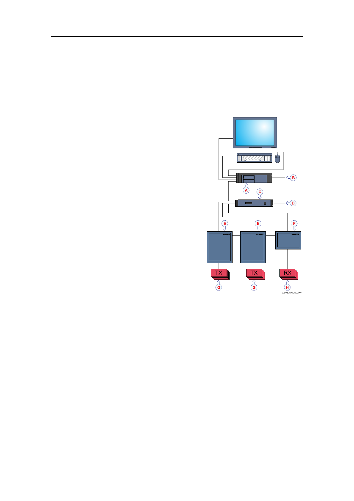
ThesystemdiagramidentiesthemaincomponentsofabasicEM124system.Only
themainconnectionsbetweentheunitsareshown.Detailedinterfacecapabilitiesand
powercablesarenotshown.
AHydrographicW ork
Station
BInterfaces:
•Soundspeed
sensors
•Tide
•Centredepth
output
CProcessingUnit
DInterfaces:
•Positioning
systems
•Attitude(roll,
pitchandheave)
•Soundspeed
sensor
•Velocity
•Clock
•Trigger
input/output
•Clocksynchronisation(1PPS)
ETransmitterUnit(TXU)
FReceiverUnit(RXU)
GTransmittransducermodules
HReceivetransducermodules
12
443140/A
Systemunits
Topics
Transducerdescription,page13
TransmitterUnitdescription,page14
ReceiverUnitdescription,page14
ProcessingUnitdescription,page14
HydrographicWorkStationdescription,page15
Transducerdescription
KongsbergEM124
Atransducerisadevicethatconvertsoneformofenergytoanother.Inanechosounder
systemthetransducerconvertsbetweenelectricenergyandsound.
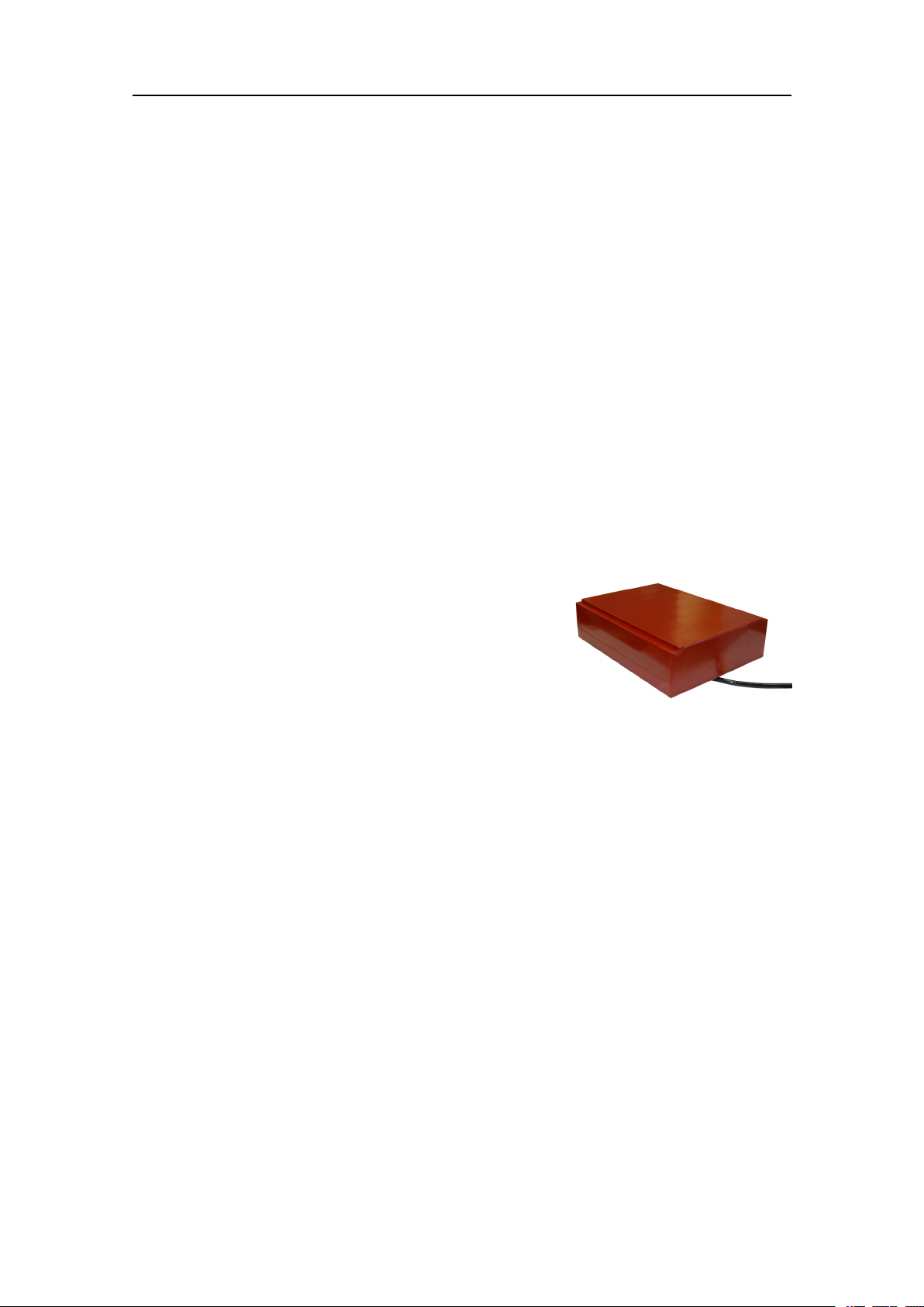
TheEM124usesseparatetransducerarraysfor
transmittingandreceivingsoundpulses.Both
transducerarrayshaveseveralmoduleswhichare
assembledinmountingframes.
Thetwotransducerarraysarenormallymountedas
“T”or“L”congurationsunderthevessel’shull(Mills
Crossconguration).Thetransmittransducerarray
Receivetransducermodule
shouldbealignedparalleltothevessel’skeel.The
receivertransducerarrayshouldbealigned90degreesonthekeel.Bothtransducer
arraysshouldbehorizontalonaplaneonthekeel.
Thetransmittransducerarraycontainsupto96modulesinaccordancewiththechosen
beamwidth.Eachmodulecontains18elementsarrangedinrowsof6elements.Each
elementisindividuallyconnectedtoitscorrespondingtransmitterintheTransmitter
Unit(s).Itcanthusbedrivenwithanuniqueamplitudelevelandphasetoallowforming
oftherequiredtransmitsectorswithindividualsteering.
Thereceivetransducercontainsupto16modulesinaccordancewiththechosen
beamwidth.Eachmodulecontains8transducerstaves,andthesehaveindividual
electricalconnectionstotheircorrespondingpreampliersintheReceiverUnit(s).Each
stavecanthusbegivenuniqueamplitudeandphasecontroltoallowformingofthe
requiredreceivebeams.
443140/A
13
KongsbergEM124InstallationManual
TransmitterUnitdescription
TheEM124TransmitterUnithasalltransmitelectronics,likecontrolprocessors,power
ampliers,powersupply,capacitorbatteryandEthernetinterface.
TheTransmitterUnitisawall-mountedsteelcabinetwithintegratedshockandvibration
absorbers,designedforbulkheadmounting.One19inchsub-rackiscontainedinthe
cabinet.Thenumberofcircuitboardsinthesub-rackwilldependuponthechosen
transducerconguration.
TwistedpairEthernetisusedfordatacommunicationwiththeProcessingUnit.
TheTransmitterUnitisnormallylocatedina"sonarroom"closetothetransducerarrays.
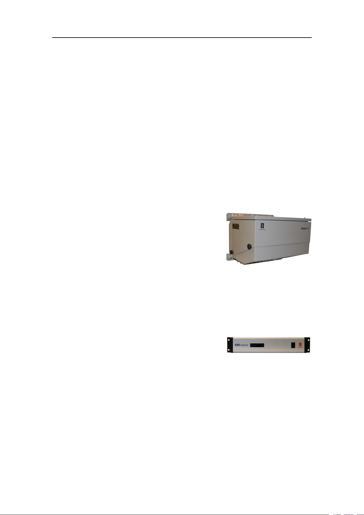
ReceiverUnitdescription
TheEM124ReceiverUnithasallreceiveelectronics,likecontrolprocessor,ampliers,
Analog-to-DigitalConverters,powersupplyandEthernetinterface.
TheReceiverUnitisasmallwall-mountedsteelcabinet
withintegratedshockandvibrationabsorbers,designed
forbulkheadmounting.Thenumberofcircuitboards
willdependuponthechosentransducerconguration.
TwistedpairEthernetisusedfordatacommunication
withtheProcessingUnit.
TheReceiverUnitisnormallylocatedina"sonar
room"closetothetransducerarrays.
ProcessingUnitdescription
TheEM124ProcessingUnitisprovidedtoprocessthesignalstoandfromthe
TransmitterandReceiverUnits.
TheEM124ProcessingUnitisanindustrial
computerusingbothCOTS(commercialoff-the-shelf)
componentsandcustommadecomponents.Theunitis
designedandtestedforruggeduse.
TheProcessingUnitperformsthereceiverbeamforming,bottomdetection,andmotion
andsoundspeedcorrections.Itcontainsallinterfacesfortime-criticalexternalsensors
suchasvesselattitude(roll,pitch,headingandheave),vesselpositionandexternal
clock.Morethanonesensorofeachtypemaybeconnectedsimultaneously,withonein
useandallofthemlogged.
TheProcessingUnitcontrolstheTransmitterandReceiverunitsviaEthernet
communication,andisalsointerfacedtotheOperatorstationviaEthernet.
The48VoutputfromtheProcessingUnitcanbeusedforremoteon/offcontrolofthe
TransmitterandReceiverUnits.
14
443140/A

KongsbergEM124
TheProcessingUnitisnormallylocatedina"sonarroom"closetothetransducerarrays.
Theunitcanalsobeplacedinthe"surveyroom"oronthebridge.
HydrographicWorkStationdescription
TheHydrographicWorkStationistheoperatorstationfortheEM124.
Adedicatedmaritimecomputerisprovidedwiththe
EM124MultibeamEchoSounder.Itissetupwith
allnecessarysoftware.
TheHydrographicWorkStationisbasedonthe
Microsoft
TheHydrographicWorkStationisnormallymounted
neartheoperatorworkspace.
®
Windows10operatingsystem.
443140/A
15

KongsbergEM124InstallationManual
Supportinformation
ShouldyouneedtechnicalsupportforyourEM124youmustcontactaKongsberg
Maritimeofce.Alistofallourofcesisprovidedonourwebsite.Youcanalsocontact
ourmainsupportofceinNorway.
A24hourtelephonesupportservicemayalsobeavailabledependingofthelevelof
SLA(ServiceLevelAgreement).
•Companyname:KongsbergMaritimeAS
•Address:Strandpromenaden50,3190Horten,Norway
•Website:https://www.km.kongsberg.com
•E-mailaddress:km.hydrographic.support@kongsberg.com
16
443140/A

Preparations
Topics
Tools,equipmentandconsumablesrequiredforEM124installation,page17
Personnelqualications,page18
Preparations
Sonarroomrequirements,page19
Wheretoinstallthetransducer,page22
Acousticnoise,page27
Tools,equipmentandconsumablesrequired forEM124installation
InordertodotheEM124installation,allnecessarytoolsandequipmentformechanical
work,cabinetinstallationandelectricalwiringmustbeavailable.
Itisnotpracticaltoprovideadetailedlistofallnecessarytoolsandequipment.Y oumust
beequippedwithastandardsetoftools.Thistoolsetmustcomprisethenormaltoolsfor
electronicandelectromechanicaltasks.Thisincludesdifferentscrewdrivertypes,pliers,
spanners,acablestripper,asolderingiron,etc.Eachtoolmustbeprovidedinvarious
sizes.W erecommendthatalltoolsaredemagnetizedtoprotectyourequipment.
However,youmustmakesurethatthefollowingspecializedtoolsareavailable.
•Allnecessarytoolsandconsumablesrequiredforwelding
•Allnecessarytoolsandconsumablesrequiredforphysicalinstallationoftransducer
framesandtransducermodules
•Allnecessarytoolsandconsumablesrequiredforelectricalinstallations
•AnarticulatedjackorsimilararrangementcapableofliftingtheindividualEM124
units
•Torquewrench
443140/A
17

KongsbergEM124InstallationManual
Note
Ifyouneedspecicconsumables,orifspecialtoolsand/ortestinstrumentsarerequired,
theseareidentiedintherelevantprocedure(s).
Personnelqualications
TheinstallationoftheEM124isademandingtask.Itisveryimportantthatthe
personnelinvolvedintheinstallationtasksarecompetentandexperiencedcraftsmen.
Asaminimum,thefollowingcertiedcraftsmenmustbeavailable.
•ServiceengineerfromKongsbergMaritime
•Welders
•Electricians
Note
Thequalityoftheweldingiscriticaltothesafetyofthevessel.Weldingmustonlybe
donebyacertiedwelder .
Ifapplicable,thenalinstallationweldsmustbeapprovedbythevessel’ snational
registry,thecorrespondingmaritimeauthorityand/orclassicationsociety.Observethe
relevantrulesandregulationsrelatedtowelding.
18
443140/A

Preparations
Sonarroomrequirements
Topics
Environmentalrequirements,page19
Sizeandaccessrequirements,page19
Requirementsforinsulation,heatingandventilation,page20
Requirementsforelectricalinstallations,cablesandcommunication,page20
Environmentalrequirements
TheEM124unitsmustbeinstalledinadryanddust-freeenvironment.Theunitsarenot
fullyprotectedagainsthumidity,dustorwater.
Itisimportantthatthesonarroomiskeptdry.TheEM124unitsmustnotbeexposed
toexcessivetemperatures,dust,moistureorhumidity.Suchconditionscancause
corrosiveattacksandsubsequentfailurestotheelectroniccircuitry.Visitthesonarroom
atregularintervalstochecktemperatureandhumidity,andtakethenecessaryactions
iftheenvironmentalconditionsarepoor.
Avoidrunninglargepowercablestroughthesonarroom.
ObservetheenvironmentalspecicationsrelatedtotheEM124units.
Sizeandaccessrequirements
Awelldesignedsonarroomwithawellttedsizeandeasyaccessreducestheriskof
corrosion,andsimpliesmaintenance.Thisincreasessystemreliability .
Thesonarroommustbelargeenoughtohouseallthesystemunits.Theroommust
provideenoughspacetoallowefcientmaintenance.Y oumustbeabletokeepallthe
cabinetdoorsfullyopenwithoutunduerestrictiontoyourmovements.
1Theroommustnotbeusedforanyotherheavymachinery.
2Theroommustnotbeunnecessarilyobstructedbygirders,pipesetc,whichmay
causeinstallationproblemsorimpedemaintenance.
3Thesonarroommustbeaccessibleunderallconditionsatseaorataberth.
4Alldoorsorhatchesmustbedesignedsothatthetoolsandequipmentcanbe
removedwithoutbeingdisassembled.
443140/A
19

KongsbergEM124InstallationManual
Requirementsforinsulation,heatingandventilation
Thebulkheadsinthesonarroomshouldbeinsulatedandprovidedwithaninteriorwall
tothedeck.Theroomshouldbeequippedwithheaterandconnectedtothevessel's
ventilationsystem.
Heatingrequirements
Heatingisaneffectivemethodforreducinghumidity.Theheaterinthesonarroommust
dimensionedtomaintaintheequipmentwithinitsenvironmentaltolerances.
ObservetheenvironmentalspecicationsrelatedtotheEM124units.
Ventilationrequirements
Thesonarroomshouldbeconnectedtothevessel'sventilationsystemtoensureasupply
ofcoolingair.Ifaventilationsystemisnotavailable,installtwo3”pipesfromthesonar
roomtoasuitablefreshairlocationondeck.
Thefreshairshouldentertheroomasclosetotheooraspossible,andshouldbe
extractedfromashighaspossible.Afunnelshapeddrip-collectormustbemounted
belowtheventpipestodivertmoisturetothebilge.Onthemaindeck,thebest
ventilationisprovidedwhentheoutletpipeisatleastfourmetershigherthantheinlet
pipe.T okeepoutseawater,rainandspray,theventilationpipesmustbettedwith
goosenecksoranequivalentdesign.
Note
Ifthevesselislikelytooperateintropicalconditions,asuitableairconditioningsystem
mustbeinstalled.Theairconditioningsystemmustbeabletoprovideanambient
temperaturethatdoesnotexceedthemaximumoperatingtemperaturesoftheEM124
unitsthatareinstalledintheroom.
Requirementsforelectricalinstallations,cablesand communication
Theelectricalinstallationsinthesonarroommustmeetminimumrequirementsto
providesuitablelightsandsupplypower.
Lightrequirements
Thesonarroommustbeequippedwithsuitablelightingtosimplifytheinstallation
andtoaidfuturemaintenance.
Communicationrequirements
Thesonarroomshouldbeequippedwithatelephone,anintercomsystem,oranyother
meansoforalcommunicationbetweenthesonarroomandthebridgeand/orcontrol
room(s).
20
443140/A

Preparations
Powerrequirements
Eachunitinthesonarroomshouldbeprovidedwithaseparatecircuitbreakeronthe
mainssupply.
Propervesselgroundmustbeprovided.
Aminimumnumberofadditionalelectricaloutletsmustbeprovidedforotherequipment.
Cablingrequirements
ThesonarroomunitsareconnectedtootherEM124unitslocatedindifferent
compartmentsonthevessel.Theunitsmayalsobeconnectedtoperipheraldevices.If
thesecablespassthroughhatchesorareaswheretheymaybedamaged,theymustbe
runinconduits.Minimum2”conduitisrecommended.
Makesurethatallsystemcablesareproperlyconnectedandsecured,andinstalled
withsomeslack.Theslackisessentialtowithstandvibrations,andtofacilitatefuture
maintenanceandreplacements.
443140/A
21

KongsbergEM124InstallationManual
Wheretoinstallthetransducer
Topics
Introductiontotransducerlocation,page22
Mountthetransducerdeep,page22
Avoidprotrudingobjectsnearthetransducer,page23
Keepthetransducerfarawayfromthepropellers,page24
Mountthetransduceratasafedistancefrombowthruster(s),page24
Summaryandgeneralrecommendations,page24
Introductiontotransducerlocation
Asingleanswertothequestion"wheretoinstallthetransducer"cannotbegiven.
Thephysicallocationofthetransducerdependsonthevessel'sdesignandconstruction,
howthehullisshaped,andhowthewaterrunsalongthehull.Therearehowevera
numberofimportantguidelines,andsomeoftheseareevenconicting.
Note
Theinformationheremustbeconsideredasgeneraladvice.EachEM124installation
mustbehandledseparatelydependingonthehulldesignandtheotherelectricaland
mechanicalsystemsinstalledonthevessel.
Mountthetransducerdeep
InordertoachievethebestpossibleEM124performance,mountthetransduceras
deepaspossibleunderthevessel’shull.
Thereareseveralreasonsforthisrecommendation.
Flownoise
Considerthesituationswhenthevesselisunloaded,andpitchinginheavyseas.The
vesselisridinghigh,andthebowmayevenbeliftedoutofthewater.Thiswillcausea
lotofairtofollowtheshapeofthehull.
Theupperwaterlayersoftheseacontainamyriadofsmallairbubblescreatedbythe
breakingwaves.Inheavyseastheupper5to10metresmaybelledwithair,andthe
highestconcentrationswillbenearthesurface.Airbubblesabsorbandreectthesound
energy,andtheymayinworstcasesblockthesoundtransmissionaltogether.
22
443140/A

Preparations
Cavitation
Cavitationistheformationofsmallairbubblesclosetothetransducerface.Thebubbles
appearbecausethelocalpressurebecomesnegativeduringpartsoftheacousticpressure
cycles.Thecavitationthresholdincreaseswiththehydrostaticpressure.Thenoiseis
madewhenthebubblesimplode.
Transmittinginair
Thetransducermustneverbeliftedfreeofthewatersurface.Ifthetransduceris
activatedwhenoutofthewateritmaybedamagedbeyondrepair.Mountingthe
transduceratadeeppositiononthehullwillinnormallypreventthis.
Slamming
Slamminghappensifthevesselhullclimbsoutofthewaterinheavyseas.Theforceof
thewaterwhenthehullfallsdownmaypushthetransducerup,andmaycausedamage
bothtothetransducerandtoitsmounting.Thisisespeciallyimportantforlowfrequency
Transducerswithlargefaces.Theeffectofslammingcanbereducedbymountingthe
transducerasdeepaspossibleonthehull.
Note
KongsbergMaritimeAStakesnoresponsibilityforanydamagestothetransducer,the
cableorthemountingarrangement,causedbyslamming.
Avoidprotrudingobjectsnearthetransducer
Objectsprotrudingfromthehullwillgenerateturbulenceandownoise.Thiswill
reducetheEM124performance.
Protrudingobjectsmaybezincanodes,transducersoreventhevessel'skeel.Holesand
pipeoutletsarealsoimportantnoisesources,aswellasroughsurfacescausedbybad
welding.Eventracesofsealingcompound,sharpedges,boltsoremptyboltholeswill
createnoise.Alltheseprotrudingobjectsmayactasresonantcavitiesamplifyingthe
ownoiseatcertainfrequencies.
Donotplaceatransducerinthevicinityofprotrudingobjects,andespeciallynotclose
behindthem.Makesurethatthesurfaceofthetransducerface,thehullplatingandputty
aroundthetransducerisasevenandsmoothaspossible.Mountingscrewsorboltsmust
notbeextrudingfromthetransducer,theinstallationhardwareorthehullplating.If
necessary,grindandpolishallsurfaces.
443140/A
23

KongsbergEM124InstallationManual
Keepthetransducerfarawayfromthepropellers
Thepropulsionpropellersisthedominantnoisesourceonmostvessels.Thenoise
iseasilytransmittedthroughthewater.Thisnoisemayoftenreducetheoverall
performanceofyourEM124.
Thetransducermustbeinstalledasfarawayfromthepropellersaspossible.Thebest
positionsarethereforeontheforepartofthehull.Positionsoutsidethedirectlineof
sightfromthepropellersarebest.
Onsmallvesselswerecommendmountingthetransduceronthatsideofthekeelwhere
thepropellerbladesmoveupwards.Thisisbecausethepropellercavitationisweakest
onthatside.Thecavitationstartswhenthewaterowsinthesamedirectionasthe
propellerblades.Thisiswherethepropellerbladesmovedownwards.
Mountthetransduceratasafedistancefrombowthruster(s)
Bowthrusterpropellersareextremelynoisy.Whenyoudecidewheretoplacethe
transducer,youmustconsiderthenoisecreatedbymostbowthrusters.
Wheninoperation,thenoiseandcavitationbubblescreatedbythethrustermaymake
yourEM124MultibeamEchoSounderuseless,almostnomatterwherethetransduceris
installed.Whenthebowthrustersarenotinoperation,thetunnelcreatesturbulence.If
yourvesselispitching,thetunnelmaybelledwithairoraeratedwaterintheupper
positionandreleasethisinthelowerposition.
Ingeneral,thetransducershouldthereforebeplacedwellawayfromthebowthruster(s).
However,thisisnotaninvariablerule.Certainthrusterdesigns-combinedwiththeir
physicallocationsonthehull-maystillofferasuitablelocationforthetransducer,even
closetothethruster.Ifyouareindoubt,consultanavalarchitect.
Summaryandgeneralrecommendations
Someoftheinstallationguidelinesprovidedfortransducerlocationmaybeconicting.
Forthisreason,eachvesselmustbetreatedindividuallyinordertondthebest
compromise.
Ingeneral,themostimportantfactoristoavoidairbubblesinfrontofthetransducer
face.Forthisreason,therecommendedtransducerlocationisnormallyintheforepartof
thehull,wellaheadofthenoisecreatedbythebowwave.
Themaximumdistancefromthebowisnormallyequaltoonethirdofthetotalwater
linelengthofthehull.
Note
Mountingthetransducermorethan10–15metersfromthebowmaycauseproblems
withtheturbulentow.
24
443140/A
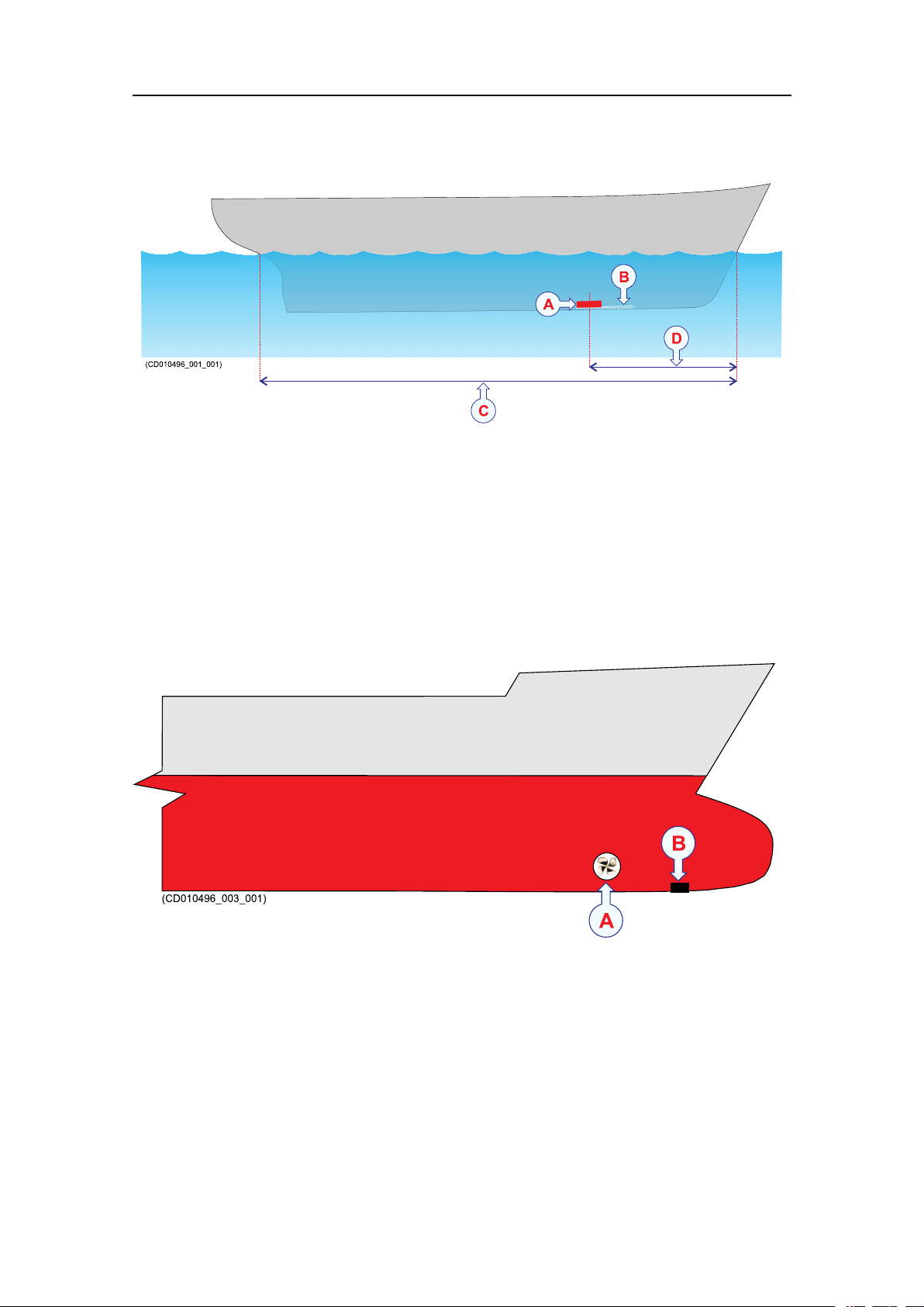
ATransducer
BInclinationangle
CHulllengthatwaterline
Preparations
DMaximum1/3ofthehulllengthatwaterline(C)
Ifthevesselhullhasabulbousbow,thismaywellbeagoodtransducerlocation,but
alsointhiscasetheowpatternoftheaeratedwatermustbetakenintoconsideration.
Theforemostpartofthebulbisoftenagoodlocation.
AThruster
BTransducerlocation
Thisappliestothevesselinnormaltrimandspeed.
443140/A
25

KongsbergEM124InstallationManual
Important
Thetransducermustnothaveanegativeinclinationanglecomparedtowaterow.
Donotplaceatransducerinthevicinityofprotrudingobjects,andespeciallynotclose
behindthem.
Makesurethatthesurfaceoftheresultinginstallationisassmoothandstreamlinedas
possible.
26
443140/A

Acousticnoise
Aswithanyotherhydroacousticsystems,thequalityoftheEM124echodataand
presentationsaresubjecttounwantedacousticnoise.Theechoesfromanylargeand
smalltargetmustbedetectedinsidethenoise.
Itisimportantthatwekeepthenoiselevelaslowaspossible.Theisnecessarytoobtain
longrangeanddependableinterpretationsoftheechoes.Evenwiththeadvancednoise
lteringofferedbytheEM124,wemustaddressthenoisechallenge.Thisisimportant
duringtheplanningandpreparationsfortheEM124installation.
Topics
Contributingfactors,page27
Selfnoise,page28
Ambientnoise,page31
Preparations
Electricalselfnoise,page31
Somemeanstoreduceacousticnoise,page31
Contributingfactors
Severalfactorsarecontributingtotheperformanceofthehydroacousticequipment
usedonboardavessel.
Factorscontributingtotheperformanceofthehydroacousticequipmentusedonboarda
vesselare:
•Thequalityandpropertiesofthetransmittedsignal
•Thequalityofthereceivingsystem
•Theoperationalsettingsmadeduringoperation
•Thepropertiesofthetarget(s)
•Thesignal-to-noiseratio
Themajorityofthesefactorscanneitherbecontrollednorimprovedbymeans
ofinstallationmethodsortransducerlocations.Thequalityandpropertiesofthe
transmittingandreceivingsystemsarekeyfactorsduringourproductdevelopment,while
ourenduserdocumentationaimstohelptheusertomaketherightltersettingsduring
operation.Asforthetargetproperties,thereisnothinganyofuscandowiththose.
Thesignal-to-noiseratio,however,canbeimprovedbymakingthecorrectchoices
duringinstallation.
Signal-to-noiseratio(oftenabbreviatedSNRorS/N)isameasureusedin
scienceandengineeringthatcomparesthelevelofadesiredsignaltothelevelof
backgroundnoise.Itisdenedastheratioofsignalpowertothenoisepower,often
expressedindecibels.Aratiohigherthan1:1(greaterthan0dB)indicatesmore
443140/A
27

KongsbergEM124InstallationManual
signalthannoise.WhileSNRiscommonlyquotedforelectricalsignals,itcan
beappliedtoanyformofsignal[...].
http://en.wikipedia.org/wiki/Signal_to_noise_ratio(September2013)
Thesignalistheechothatwewanttoknowsomethingabout,whilethenoiseisany
unwantedsignalsordisturbances.Theechomustbedetectedinthenoiseandthereforeit
isnecessarytokeepthenoiselevelisaslowaspossibleinordertoobtainlongrange
anddependableinterpretation.
Thenoisethatcontributestothesignaltonoiseratiomaybedividedintothefollowing
typesofnoise:
•Selfnoise
•Ambientnoise
•Electricalnoise
•Reverberation
AThetransducercanpickupnoisefrom
•Biologicaldisturbances
•Interference
•Cavitation
•Propellernoise
•Flownoise
•Acousticnoisefromotherhydroacousticsystems
BThetransducercableislong,andmaypickupelectricnoisefromgenerators,
pumps,coolingsystemsandotherelectricorelectromechanicaldevices.
CThepreampliersareverysensitive,andtheycaneasilypickupelectricalnoise
frominternalandexternalpowersupplies.Thepreampliersarealsovulnerablefor
analoguenoisecreatedbytheirownelectroniccircuitry .Digitalnoisecreatedby
theconverterandprocessingcircuitrycanalsocreateproblems.
DConverterstransformtheanalogueechoestodigitalformat.
ESignalprocessingcircuitrycancreatedigitalnoise.
Selfnoise
Anyvesselequippedwithahydroacousticsystem(forexampleechosounderorsonar)
willproducemoreorlessselfnoise.
Therearemanysourcesofsuchselfnoise.W ewillheregointosomedetailsinorderto
analysethedifferentsourcesofselfnoiseonavesselandhowtheymayinuenceupon
thenoiselevelofthehydroacousticinstruments.
28
443140/A
Preparations
Machinerynoise
Themaincontributortomachinerynoiseisusuallythemainengineonboardthevessel.
Thecontributionfromauxiliarymachinerymay,however,beconsiderable,especiallyif
itisinpoorshape.Themachinerynoisecanbetransmittedtothetransduceras:
•Structure-bornenoisethroughtheshipstructureandthetransducermountings
•Water-bornenoisethroughthehullintothewatertothetransducer
Electricalnoise
Modernvesselsarenormallyequippedwithalotofelectricinstrumentssuchas
hydroacousticsystems,radars,navigationsystems,andcommunicationequipment.
Anyelectricinstrumentsmayinsomecasescauseelectricalinterferenceandnoise.
Internationalregulationsandcerticationsareusedtocontrolandreducethis,buteven
thesearelimitediftheelectricalsystemsarepoorlyinstalledand/ormaintained.
Propellernoise
Propellernoiseisoftenthemainsourceofnoiseathighervesselspeeds.V ariablepitch
propellersorfastmovingpropellersusuallymakemorenoisethanxedpropellersor
slowmovingpropellers.
Propellernoiseisusuallywater-borne.Insomecases,however,shaftvibrationsor
vibrationsinthehullnearthepropellermaybestructure-bornetothetransducer.Ifa
propellerbladeisdamaged,thismayincreasethenoiseconsiderably.
Propellercavitationisaseveresourceofnoise."Singing"propellersmightbeasourceof
noise,whichinterferesatdiscretefrequencies.Insomecasesstaticdischargefromthe
rotatingpropellershaftmaybequitedisturbing.
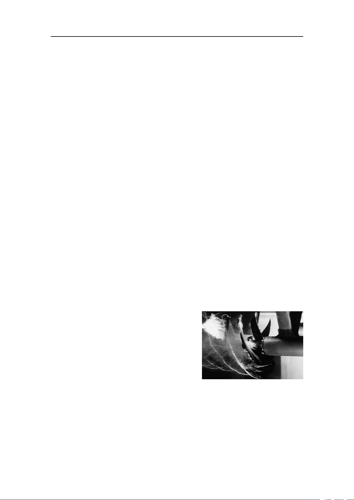
Cavitation
Cavitationistheformationofsmallairbubbles
closetothetransducerface.Thebubblesappear
becausethelocalpressurebecomesnegative
duringpartsoftheacousticpressurecycles.
Thecavitationthresholdincreaseswiththe
hydrostaticpressure.Thenoiseismadewhen
thebubblesimplode.
Cavitationnoisemayappearnearextruding
objectsathigherspeeds,butmoreoftenitis
causedbythepropellers.Propellercavitationisaseveresourceofnoise.Thecavitation
startswhenthewaterowsinthesamedirectionasthepropellerblades.Thisiswhere
thepropellerbladesmovedownwards.
Insomecasesaresonantphenomenonissetupinaholenearthehull.Thissoundwill
haveadiscretefrequency,whileallotherownoisewillhaveawidefrequencyspectrum.
(ImagefromU.S.Navyinthepublicdomain.)
443140/A
29
KongsbergEM124InstallationManual
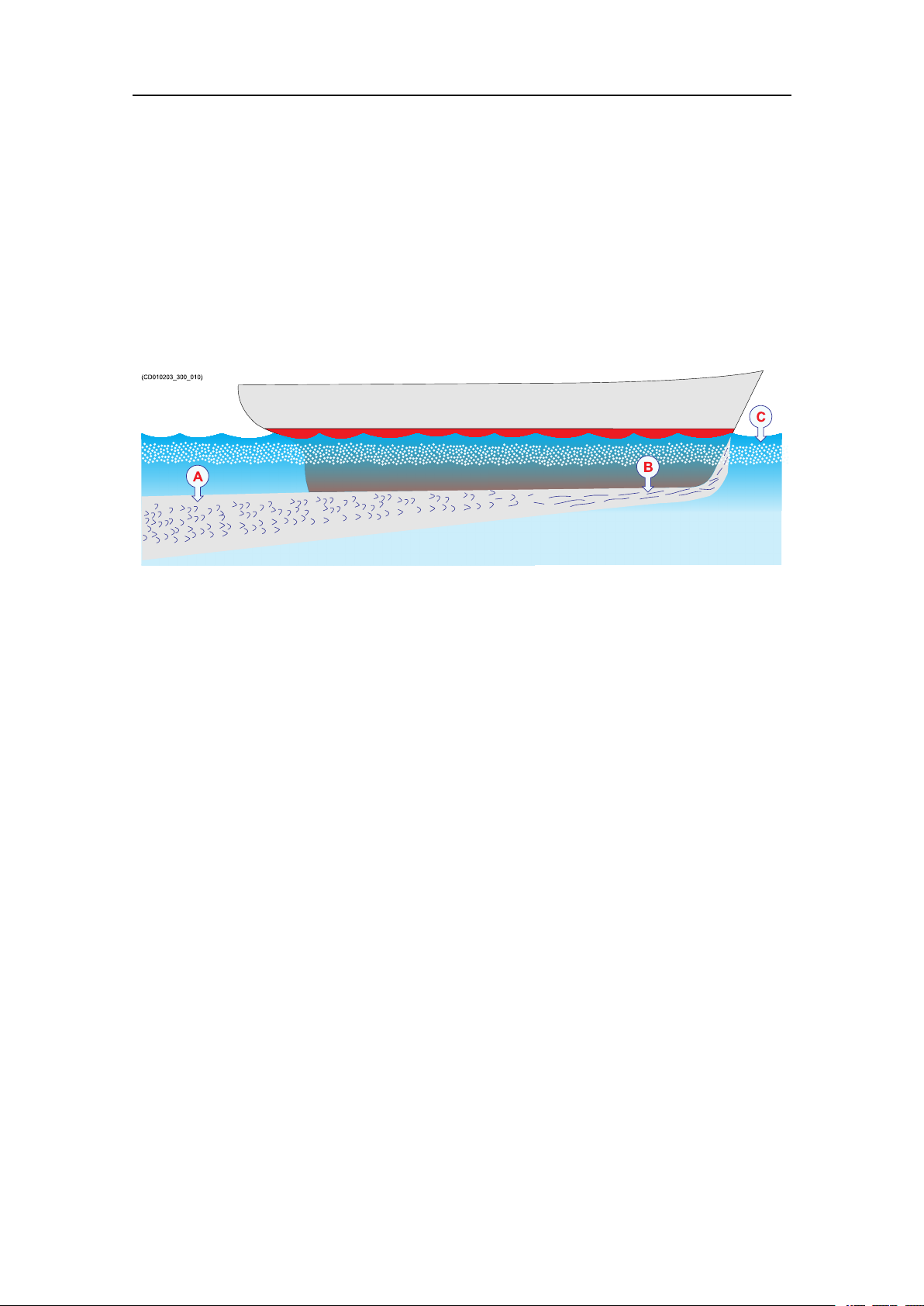
Flownoise
Theupperwaterlayersoftheseacontainamyriadofsmallairbubblescreatedbythe
breakingwaves.Whenthehullmovesthroughwateritwillcauseadisturbance,andthis
willgeneratefriction.Thefrictionzoneiscalledtheowboundarylayer.Theowin
thisboundarylayermaybelaminarorturbulent.
•Thelaminarowisanicelyordered,parallelmovementofthewater.
•Theturbulentowisadisorderlyowpattern,fullofeddies.
ATurbulentow
BLaminarow
CAirbubbles
Airbubblesabsorbandreectthesoundenergy,andtheymayinworstcasesblockthe
soundtransmissionaltogether.
Theboundarylayerincreasesinthicknesswhenitbecomesturbulent.Theboundary
layeristhinintheforwardpartofthevesselhull,andincreasesasitmovesaft.The
thicknessdependsonshipsspeedandontheroughnessofthehull.Allobjectssticking
outfromthehull,ordentsinthehull,willdisturbtheowandwillincreasethethickness
oftheboundarylayer.Whentheowspeedishigh,theturbulencecanbeviolentenough
todestroytheintegrityofthewater.Smallvoidsorcavitiesinthewaterwilloccurand
thisiscalledcavitation.
Rattlenoise
Rattlenoisemaybecausedbylooseobjectsinthevicinityofthetransducer,likexing
bolts.Therattlemayalsocomefromlooseobjectsinsidethehull.
Interference
Interferencefromotherhydroacousticequipmentonboardthesamevesselmaybean
annoyingsourceofdisturbance.Unlessthesamefrequencyisusedformorethanone
pieceofequipmentonlythetransmittedpulsewillcontributetotheinterference.
Inphysics,interferenceisthephenomenoninwhichtwowavessuperposeeach
othertoformaresultantwaveofgreaterorloweramplitude.Interferenceusually
referstotheinteractionofwavesthatarecorrelatedorcoherentwitheachother,
eitherbecausetheycomefromthesamesourceorbecausetheyhavethesameor
30
443140/A
 Loading...