

KONNWEI KW309 User Manual
1
User Manual
KONNWEI KW309 CAN OBDII+EOBD Code Reader
Specifications
Display: Back lit, 128 x 64 pixel display with contrast adjustment
1)
Operating Temperature: 0 to 60°C (32 to 140 F°)
2)
Storage Temperature: -20 to 70°C (-4 to 158 F°)
3)
External Power: 8.0 to 18.0 V power provided via vehicle battery
4)
Accessories Included
OBD II cable – Provides power to tool and communicates between tool and vehicle.
Selects the desired language:
English, French, German, Dutch, Spanish, Russian, Portuguese.

2
1.0 General Information: On-Board Diagnostics (OBD) II
The first generation of On-Board Diagnostics (called OBD I) was developed by the California Air Resources Board (ARB) and
implemented in 1988 to monitor some of the emission control components on vehicles. As technology evolved and the desire to
improve the On-Boar d Diagnostic sys tem increased, a new gene ration of On-Board Diagnostic s ystem was de veloped. This
second generation of On-Board Diagnostic regulations is called “OBD II”.
The OBD II system is designed to monitor emission control systems and key engine components by performing either
continuous or periodic tests of specific components and vehicle conditions. When a problem is d etected, the OBD II system
turns on a warning lamp (MIL) on the vehicle instrument
panel to aler t the driver typically by the phrase of “Check Engine” or “Service Engine Soon”. The system will also store
important information about the detected malfunction so that a technician can ac curately find and fix the problem. Here b elow
follow three pieces of such valuable information:
1) Whether the Malfunction Indicator Light (MIL) is commanded ‘on’ or ‘off’;
2) Which, if any, Diagnostic Trouble Codes (DTCs) are stored;
3) Readiness Monitor status.
1.1 Location of the Data Link Connector (DLC)
The DLC (Data Link Connector or Diagnostic Link Connector) is the standardized 16-cavity connector wher e diagnostic
scan tools interface with the v ehicle’ s on-board computer. Th e DLC is usually located 12 inches from the center of the
instrument panel (dash), under or around the driver ’s side for most v ehicles, IF Data Link Connector is not located und er
dashboard, a label should be there telling location, For some Asian and European vehicles, the DLC is located behind the
ashtray and the ashtray must be removed to a ccess the connect If the DLC cannot be found, refer to the vehicle ’s service
manual for the location.
1.2 Diagnostic Trouble Codes (DTCs)
OBD II Diagnos tic Trouble Codes are codes that are stored by the on—board computer diagnostic system in
response to a problem found in the vehicle, These codes identify a particular problem area and ar e intended to provide
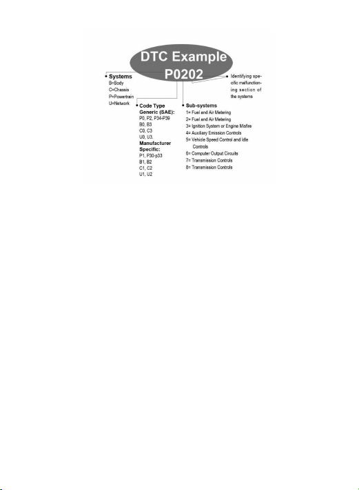
you with a guide as to where a fault might be occurring within a vehicle. OBD II Diagnostic Trouble Codes consist of a
five-digit alphanumeric code, The first character, a letter, identifies which control system sets the code, The other four
characters, all numbers, provide add itional information on where the DTC o riginated and the operating conditions that
caused it to set, Here below is an example to illustrate the structure of the digits:
Identifying specific malfunctioning section of the systems.
3
1.3 OBDII Monitor Readiness Status
OBDII systems must indicate whether or not the vehicle * s PCM,s monitor system has completed testing on
each component. Components that have been tested will be reported as “Ready”,or “Complete” , meaning they have
been tested by the OBD II system. The purpose of recording readiness status is to allow inspectors to determine if the
vehicle * s OBD II system has tested all the components and/or systems.
The power train control module (PCM) sets a monitor to “Ready” or “Complete” after an appropriate drive cycle
has been performed. The drive cycle that enables a monitor and sets readiness codes to “Ready” varies for each
individual monitor. Once a monitor is set as “Ready” or “Complete”,it will remain in this state. A number of factors,
including erasing of diagnostic trouble codes (DTCs) with a scan tool , can result in Readiness Monitors being set to
“Not Ready” . Since the thr ee continuous monitors are constantly evaluating, they will be reported as “Ready” all of the
time. If testing of a particular supported non-continuous monitor has not been completed, the monitor status will be
reported as “Not Complete ” or ‘‘ Not Ready ”
In order for the OBD monitor system to become ready, the vehicle should be dr iven under a var iety of normal
operating conditions. These operating conditions may include a mix of highway dr iving and stop and go, city type driving,
and at least one over night—off period, For specific information on getting yo ur vehicle* s OBD monitor system ready,
please consult your vehicle owner* s manual.
1.4 OBD II Definitions
Power train Control Module (PCM) OBD II terminology for the on-board computer that controls engine and drive train.
Malfunction Indicator Light ( MIL) -- Malfunction Indicator Light (Service Engine Soon, Check Engine) is a term used for
the light on the instrument panel. It is to alert the driver and/or the repair technician that there is a pr oblem with one or

4
more of vehicle's systems and may cause emissions to excee dfeder al standards. If the MIL illuminates with a steady light,
it indicates that a problem has been detected and the vehicle should be serviced as soon as possible. Under cer tain
conditions, the dashboard light will blink or flash. This indicates a s evere problem and flashing is intended to discourage
vehicle operation. The vehicle on board diagnostic sy stem can not turn the MIL off until the necessary repairs a re
completed or the condition no longer exists.
DTC --Diagnostic Trouble Codes (DTC) that identify which section of the emission control system has malfunctioned.
Enabling Criteria -- Also termed Enabling Conditions. They are the vehicle-specific events or conditions that must occur
within the engine before the var ious monitors will set, or run. Some monitors require the vehicle to follow a prescribed
“drive cycle” r outine as part of the enabling criteria. Drive cycles vary among ve hicles and for each monitor in any
particular vehicle.
OBD II Drive Cycle - - A specific mode o f vehicle operation that pro vides conditions required to set all the readiness
monitors applicable to the vehicle to the “ready” condition. The purpose of completing an OBD II drive cycle is to force
the vehicle to run its on board diagnostics. Some form of a drive cycle needs to be performed after DTCs have been
erased from the PCM's memory. Running through a vehicle's complete dr ive cycle will “set” the rea diness monitors so
that future faults can be detected. Drive cycles vary depending on the vehicle and the monitor that n eeds to be reset.
For vehicle specific drive cycle, consult the vehicle’s Owner’ s Manual.
Freeze Frame Data --When an emissions related fault occurs, the OBD II system not only sets a code but also records
a snapshot of the vehicle operating parameter to help in identifying the problem. This set of values is referred to as Freeze
Frame Data and may include t engine parameters s uch as engine RPM, vehicle speed, air flow, engine load, fuel pressure,
fuel trim value, engine coolant s, ignition timing advance, or closed loop start.
1.5 Vehicle Coverage
The KONNWEI KW309 OBDII/EOBD Scanner is specially designed to work with all OBD II compliant vehicles, including
those equipped with the next-ge neration protocol ——Control Area Network (CAN). It is required by EPA that all 1996
and newer vehicles (cars and light truck s) so ld in the United States must b e OBD II compliant and this includes all
Domestic, Asian and European vehicles.
A s mall number of 1994 and 1995 model year gasoline vehicles are OBD II compliant. To verify if a 1994 or 1995
vehicle is OBD II compliant, check the Vehicle Emissions Control Information (VECI) Label which is located under the
hood or by the radiator of most v ehicles. If the vehicle is OBD II compliant, the label will des ignate “OBD II Certified” •
Additionally, Government regulations mandate that all OBD II compliant vehicles must have a “common” sixteen- pin
Data Link Connector (DLC).
For yo ur vehicle to be OBD II compliant it must have a 16-pin DLC (Data Link Connector) under the dash and the
Vehicle Emission Control Information Label must state that the vehicle is OBD II compliant.

5
1.6 Product Troubleshooting
Vehicle Linking Error
A communication error occurs if the scan tool fails to communicate with the vehicle’ s ECU (Engine Control Unit). You
need to do the following to check up:
• Verify that the ignition is ON;
• Check if the scan tool’ s OBD II connector is securely connected to the vehicle' s DLC;
• Verify that the vehicle is OBD2 compliant;
• Turn the ignition off and wait for about 10 seconds. Turn the ignition back to on and continue the testing.
• Verify the control module is not defective.
Operating Error
If the scan tool freeze s, then an exception occurs or the vehicle's ECU (Engine Control Unit) is too slow to respond to
requests. You need to do the following to reset the tool:
• Press and hold POWER button for at least 2 seconds to reset the scan tool.
• Turn the ignition off and wait for about 10 seconds.
• Turn the ignition bac k to on and continue the testing.Scan tool do esn't power upIf the scan tool won’t power up or
operates incorrectly in any other way, you need to do the following to check up:
• Check if the scan tool's OBDII connector is securely connected to the vehicle's DLC;
• Check if the DLC pins are bent or broken. Clean the DLC pins if necessary.
• Check vehicle battery to make sure it is still good with at least 8.0 volts.
1.7 OBDII Diagnostics
When more than one vehicle control module is detected by the scan tool, you will be prompted to select the
module where the data may be retrieved. The most often to be selected are the Power train Control Module
[PCM] and Transmission Control Module [TCM].
CAUTION: Don't connect or disconnect any test equipment with ignition on or engine running.
1)Turn the ignition off.
2)Locate the vehicle’s 16-pin Data Link Connector (DLC).
3)Plug into the scan tool cable connector to the vehicle’s DLC.
4)Turn the ignition on. Engine can be off or running.
 Loading...